
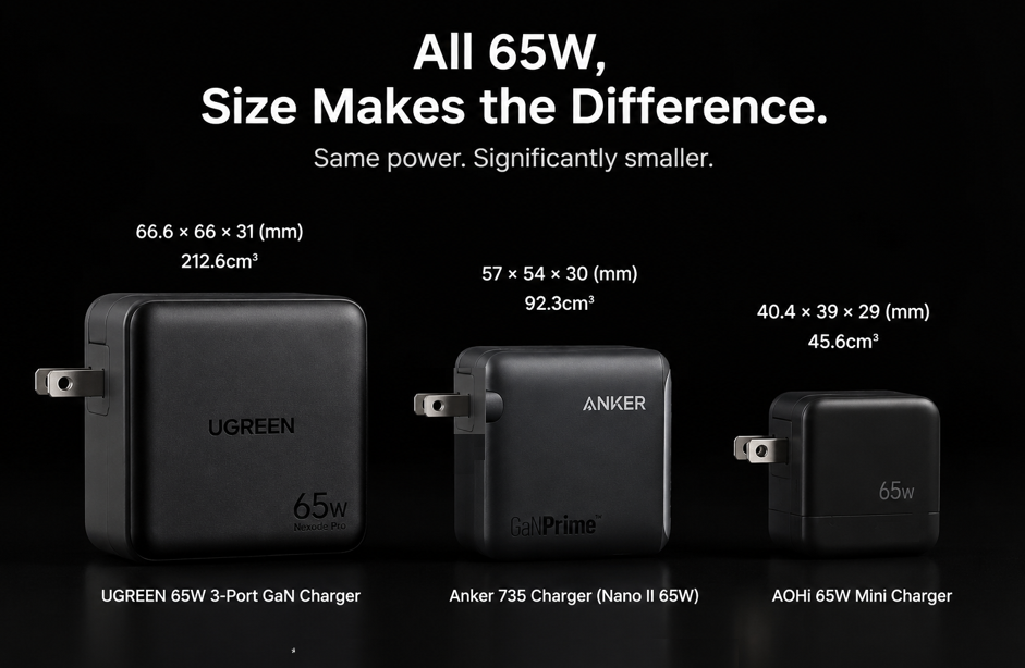
Have you ever wondered: two chargers both rated at 65W, yet one is bulky like a brick and blocks adjacent sockets on a power strip, while the other is no bigger than a lipstick and fits easily in your pocket. With identical power output, why is there such a huge difference in size, heat generation and charging efficiency?
Many people attribute this to build quality or gallium nitride technology, but few realize that the real ceiling of a charger’s size and efficiency is determined by its invisible power topology. It is the foundation of a charger, fundamentally defining how compact a charger can be, how energy-efficient it can run, and how much heat it will generate.
1. What Exactly Is Power Topology in a Charger?
1.1 Topology: The Transport Route Map of Electrical Energy
If we think of electricity inside a charger as delivery packages, power topology is the logistics route plan: it defines which path the electricity takes after entering the charger, which components it passes through, and how the voltage conversion is completed.
Put simply, power topology defines the connection method of all electronic components inside a charger and the full logic of energy transfer. It is not about exterior design, but the internal circuit architecture that inherently sets the performance limit of a charger.
1.2 The Core Mission of a Charger: Converting AC to DC
The electricity from wall sockets is high-voltage alternating current (AC), but smartphones, laptops and other electronic devices only run on low-voltage direct current (DC). The core job of a charger is to complete this energy format conversion:
- Step down high-voltage AC to low-voltage DC
- Precisely control output voltage and current
- Provide electrical isolation for safety
Different topologies are different technical routes to achieve this conversion. The quality of the route directly determines how much energy is wasted during conversion and how much actually reaches the device being charged.
1.3 Same Power, Different Performance: Root Cause Is Topology
Two chargers with the same 65W output can perform wildly differently when using different topologies: the size can differ by more than double, full-load efficiency can vary by 5 percentage points, and operating surface temperature can differ by over ten degrees Celsius. This is one of the core reasons why chargers of the same power rating can range widely in price.
2. How Topology Fundamentally Determines Charger Size
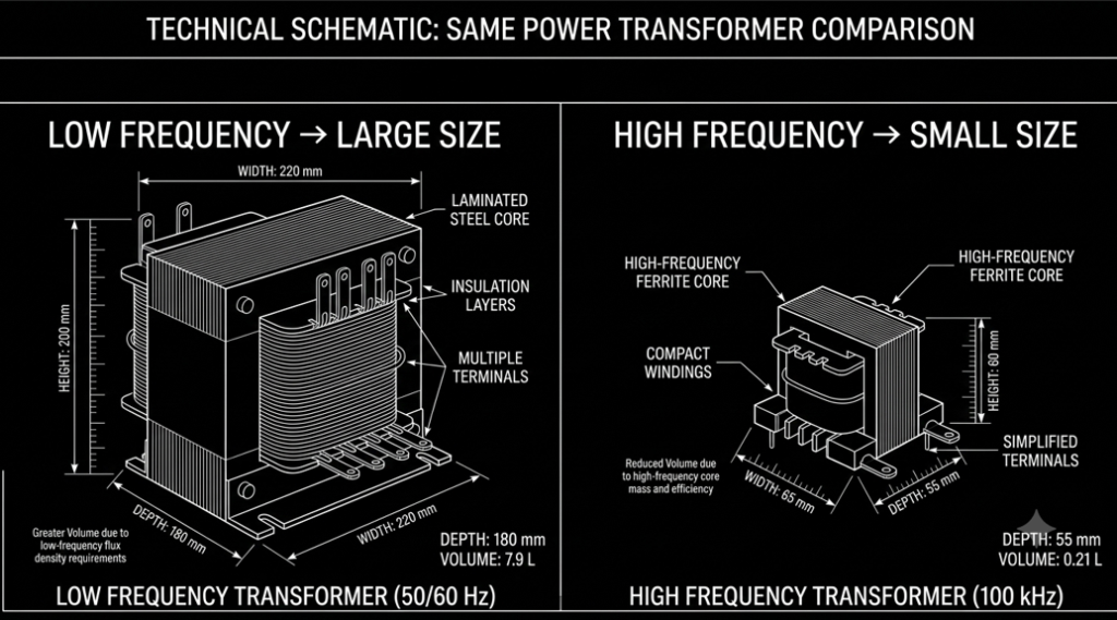
The bulkiest parts inside a charger are never chips or capacitors — they are magnetic components like transformers and inductors. Whether a charger can be made compact largely depends on how small these magnetic components can be.
2.1 Core Rule: Higher Frequency = Smaller Magnetic Components
We can think of a transformer as an energy water tank: each switching cycle is like pouring out the water from the tank. If the number of pours per second (switching frequency) is high enough, even a small tank can deliver a large total volume of water (output power) per unit of time.
This is the basic rule of power electronics: the higher the switching frequency, the smaller the required magnetic components. The key to making a smaller charger is to increase the switching frequency.
2.2 Topology Sets the Ceiling for Switching Frequency
Not all chargers can simply increase their frequency at will. The main limiting factor is the topology itself.
- Hard-switching topologies: Voltage and current overlap during switching. The higher the frequency, the greater the switching loss and heat generation. Beyond a certain frequency, overheating becomes uncontrollable, so the frequency ceiling is low, and magnetic components cannot be miniaturized.
- Soft-switching topologies: Through circuit design, switching occurs at the moment when voltage or current is zero, with almost no extra loss. The frequency can be increased by several times or even dozens of times, and the size of magnetic components can be greatly reduced.
In short, topology inherently determines whether a charger can run at high frequency, and thus directly determines the minimum possible size of its magnetic components.
2.3 Indirect Impact: Component Count and Cooling Space
Different topologies have different circuit complexity:
- Simple topologies such as Flyback have fewer components and a simpler architecture, but limited high-frequency capability;
- Complex topologies such as LLC resonant have more components, but achieve higher power density thanks to their soft-switching characteristics.
Meanwhile, more efficient topologies generate less heat, eliminating the need for large heat sinks and wide cooling gaps, further reducing overall size. High-loss topologies require larger cooling structures, making compact size difficult to achieve.
3. How Topology Inherently Affects Conversion Efficiency and Heat
A charger’s efficiency is the ratio of electrical energy actually delivered to the device to electrical energy drawn from the grid. All unused energy is dissipated as heat — lower efficiency means more heat.
There are three main types of loss during energy conversion: conduction loss, switching loss, and magnetic loss. Among them, switching loss is the core source of efficiency differences between topologies.
3.1 Switching Loss: The Key Dividing Line Between Topologies
We can compare a power switch to a household water tap:
- Hard switching: Forcing the valve open and closed while water is flowing at full force creates huge shock and splashing every time. It wears out the valve and wastes water. In a circuit, this means voltage and current coexist during switching, generating significant loss that worsens as frequency rises.
- Soft switching: Through circuit design, the valve switches exactly when the water flow drops to zero, with almost no shock or waste. In a circuit, this achieves zero-voltage switching or zero-current switching, greatly reducing switching loss even at very high frequencies.
This is the core reason why soft-switching topologies are far more efficient than hard-switching ones.
3.2 Differences in Energy Recovery Capability
During operation, a portion of energy in the transformer cannot be transferred normally (leakage inductance energy). Different topologies handle this energy differently:
- Traditional Flyback topology: This energy is directly dissipated through resistors, wasted entirely as heat;
- Active Clamp Flyback (ACF) topology: An added clamp circuit recycles the leakage inductance energy for reuse, reducing unnecessary loss and naturally improving efficiency.
3.3 Differences in Rectification Compatibility
The output side of a charger needs to convert high-frequency AC back to DC. Different topologies support different rectification solutions:
- Entry-level topologies mostly use diode rectification. Diodes have a fixed voltage drop, and loss increases significantly at higher currents;
- Mid-to-high-end topologies generally use synchronous rectification, replacing diodes with low-loss MOSFETs to further improve output-side conversion efficiency.
4. Side-by-Side Comparison of Mainstream Charger Topologies
There are four common topologies in consumer chargers today, with very distinct differences in size, efficiency and use cases, as summarized in the table below:
| Topology Type | Typical Full-Load Efficiency | Relative Size | Suitable Power Range | Common Applications |
|---|---|---|---|---|
| Flyback | 85% – 90% | Medium to large | 5W – 30W | Standard phone chargers, small electronics adapters |
| Active Clamp Flyback (ACF) | 93% – 95% | Compact | 30W – 100W | GaN fast chargers, multi-port USB-C chargers |
| LLC Resonant Converter | 95% – 97% | Very small (more advantageous at high power) | Above 100W | Laptop adapters, high-power desktop chargers |
| Totem-Pole PFC (front-end) | Improves grid-side utilization | Adds minor bulk | 65W+ high-power products | Paired with LLC for high-power-density architectures |
4.1 Flyback Topology: The Cost-Effective Choice for Low Power
Flyback is the most classic and widely used basic topology, with a simple structure and low cost. However, it is a hard-switching topology with limited frequency and efficiency ceilings. Above 30W, its drawbacks in heat and size become rapidly apparent. It is currently mainly used in low-power standard chargers.
4.2 Active Clamp Flyback (ACF): The Balanced Solution for Mid-Power Fast Charging
ACF is an upgrade from traditional Flyback. By adding an active clamp circuit to recycle leakage inductance energy, it achieves soft switching. It balances cost and performance, with significantly higher frequency and efficiency than traditional Flyback, making it the mainstream choice for consumer GaN fast chargers around 65W.
4.3 LLC Resonant Topology: The Optimal Solution for High Power and High Efficiency
LLC is a typical fully soft-switching topology. It achieves zero-voltage turn-on and zero-current turn-off through a resonant tank, with negligible switching loss and the highest full-load efficiency among all mainstream topologies. It can operate at extremely high frequencies with very small magnetic components, making it the benchmark solution for chargers above 120W.
4.4 Totem-Pole PFC: Essential Front-End for High-Power Products
PFC improves the utilization of grid power and meets energy efficiency regulations in the European Union, the United States, China and other regions. Totem-Pole PFC is currently a high-efficiency PFC solution, usually paired with LLC to form the classic Totem-Pole PFC + LLC high-power-density architecture, widely used in high-power power supplies.
5. Clarification: Gallium Nitride (GaN) Is a Boost for Topology, Not a Topology Itself
Many people mistakenly think a GaN charger refers to a new topology. This is a common misconception.
Gallium Nitride (GaN) is a power semiconductor material used to make switching transistors. It is not a power topology itself.
Think of it this way: topology is road planning, and GaN is a higher-performance car. A good road with a good car delivers the highest speed; but if the road itself is narrow and winding (low-order topology), even the best car cannot outperform a wide, smooth highway (high-order topology).
The core benefit of GaN is reducing switching loss and increasing switching speed, allowing the same topology to run at higher frequencies, further reducing size and improving efficiency. It amplifies the inherent advantages of a topology, but cannot erase the fundamental differences between different topologies.
6. Frequently Asked Questions
6.1 Why do chargers with the same power vary so much in size?
The core difference lies in the combination of three factors: topology solution, power devices, and thermal design. Products using high-order soft-switching topology + GaN devices + high-density thermal design can be made extremely compact; products using traditional hard-switching topology + silicon devices are naturally much bulkier.
6.2 Is a more complex topology always better?
Not necessarily. There is no absolute best topology — only the best fit for a given power scenario. For example, using a complex LLC topology for a 10W low-power charger only adds unnecessary cost with very little benefit. But for power above 100W, Flyback topology simply cannot meet efficiency and size requirements, and LLC is necessary.
6.3 Does a smaller charger always have higher efficiency?
Not necessarily. There are two ways to reduce size: one is to upgrade topology and materials to shrink size while maintaining efficiency; the other is to cut corners on components and reduce cooling space. This second approach makes the charger smaller, but lowers efficiency, increases heat, and may even create safety risks.
7. Practical Buying Guide for Everyday Users
- Single-port fast chargers under 30W: Standard Flyback or QR Flyback solutions are sufficient and offer the best value for daily use.
- Everyday portable chargers around 65W: Prioritize Active Clamp Flyback (ACF) + GaN solutions, which balance size, heat and price.
- High-power / multi-port chargers above 100W: Prioritize products with PFC + LLC architecture. They offer higher efficiency across all load levels, run cooler, and are more stable for long-term use.
- Efficiency reference: Look for authoritative certifications such as EU CE energy efficiency, US DOE energy efficiency, and China Energy Label. Higher certification grades generally indicate better energy efficiency performance.
8. Future Trends in Charger Topology
- Higher frequencies: As semiconductor materials advance, switching frequencies will continue to rise, further shrinking magnetic components.
- Soft-switching adoption in lower power: Soft-switching topologies originally used only in high-power applications will gradually spread to low and mid-power segments.
- Higher integration: Topology circuits and control chips will be deeply integrated, reducing external component count and further shrinking circuit area.
- Digital control: Digital power chips will dynamically adjust topology operation to achieve optimal efficiency across all load levels.
Conclusion
Power topology is the underlying architecture of a charger, inherently setting the ceiling for its size and efficiency.
To recap the full logic:
- Topology determines switching method → sets frequency ceiling → defines magnetic component size → determines overall charger size
- Topology determines loss characteristics → defines energy utilization → determines conversion efficiency → affects charger heat generation
Technologies like GaN and synchronous rectification are optimizations built on top of the base topology. For a charger that is both small and efficient, the core factor is the topology it uses. Understanding topology lets you see the essence of performance differences between chargers.