
If you’ve ever wondered why two USB-C cables that look exactly the same can have wildly different charging speeds, data performance, and video support, the answer is always found inside the cable. The outer plastic jacket tells you almost nothing about how many wires are inside, what they’re built to carry, or what features the cable supports.
Think of a USB cable like a highway system. From the outside, all you see is the road surface. But some highways only have two slow lanes, while others have eight high-speed lanes with built-in signal repeaters and full electronic toll systems. This guide breaks down the full internal structure of USB cables, how each component works, and why those internal differences matter for charging, data, and video.
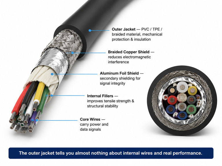
1. Physical Construction: What’s Inside a USB Cable
Every USB cable is built in layers, from the outer jacket down to the individual wires at the core. Each layer serves a specific purpose.
1.1 Outer Jacket
- Common materials: PVC, TPE, silicone, and braided nylon are the most widely used.
- Core function: Provides mechanical protection and electrical insulation, protecting the internal wires from physical wear, bending damage, and moisture.
- Beginner’s note: The jacket material mainly affects durability and how the cable feels in your hand. It does not directly determine charging speed or data transfer speed. A nice braided cable can still be a basic USB 2.0 charging-only cable.
1.2 Shielding Layers
- Common designs: Most high-quality cables use multiple shielding layers, typically an aluminum foil shield plus a braided copper shield.
- Core function: Shielding works in both directions: it reduces electromagnetic interference (EMI) coming into the cable from outside, and it prevents high-speed signals inside the cable from radiating outward. This directly improves signal integrity.
- Better shielding becomes increasingly important as USB data rates rise, especially for USB 3.x, USB4, and Thunderbolt cables.
- Basic USB 2.0 charging cables often have minimal or no proper shielding, since they do not carry high-speed signals.
1.3 Internal Wires & Fillers
Internal wire count is where the biggest differences between cables appear.
- USB 2.0 cables: Use a basic 4-wire structure — VBUS (power), GND (ground), and the D+ / D- differential signal pair for data.
- USB 3.x, USB4 and other high-speed cables: Build on the 4-wire base and add multiple high-speed differential pairs, such as SSTX+, SSTX-, SSRX+, SSRX-. Each high-speed pair usually has its own individual shield and ground wire. More wires means a thicker cable overall.
- A USB 2.0 cable may only contain four conductors, while a USB4 cable can contain well over a dozen individual conductors once high-speed pairs, ground wires, shields, and other structures are included.
- Internal fillers: Strengthen the cable’s overall tensile strength and keep internal wires positioned consistently for better structural stability.
1.4 Connectors
- Common types: Standard-A, Type-B, Micro-B, and Type-C.
- All pin assignments follow the corresponding USB specification. USB Type-C is the only current USB connector standardized to support USB Power Delivery, Alternate Mode, and USB4 over a single connector.
2. Electrical Characteristics
2.1 Power Delivery (VBUS)
- VBUS is the standard power line in every USB cable. By default, it supplies 5V.
- Through USB PD protocol negotiation, the voltage can be stepped up to 9V, 15V, or 20V. Under the USB PD 3.1 EPR specification, it can go as high as 48V.
- Default current limits for basic operation: 500mA for USB 2.0, 900mA for USB 3.0. Fast charging protocols can increase these limits dramatically through negotiation.
2.2 Data Signal Transmission
- USB uses differential signaling: instead of sending data on one wire, USB sends the same signal across a matched pair of wires. The receiver looks at the difference between them, making the connection much less sensitive to electrical noise.
- This design greatly reduces the impact of external electromagnetic interference, improves transmission stability, and lowers error rates.
- Signal voltage levels and encoding methods differ between USB generations, all following the corresponding official specifications.
2.3 Impedance Control & Shielding
- High-speed differential pairs are manufactured with tightly controlled characteristic impedance to reduce signal reflection and loss, and ensure transmission integrity.
- Impedance requirements vary slightly by signal type, and all designs must meet USB-IF specifications.
3. Generations, Speeds & E-Marker
The internal wire configuration directly determines which USB generation and feature set a cable can support.
3.1 USB 2.0
- Maximum transfer rate: 480Mbps, using the basic 4-wire structure.
- Excellent compatibility, still widely used for keyboards, mice, basic charging cables, and other low-speed peripherals.
3.2 USB 3.x SuperSpeed
- Adds SSTX / SSRX high-speed differential pairs to achieve speeds of 5Gbps and above.
- Official tiers: USB 3.2 Gen 1 = 5Gbps, Gen 2 = 10Gbps, Gen 2×2 = 20Gbps.
- Cables include individual shielding and grounding structures, with significantly better interference resistance.
3.3 USB4 Specification
- USB4 Version 1.0 supports up to 40Gbps bidirectional dual-channel transmission.
- USB4 Version 2.0 supports up to 80Gbps bidirectional bandwidth, and also supports an asymmetric 120Gbps Bandwidth Boost mode. The optional 120Gbps mode is primarily intended for display-heavy workloads, where much more bandwidth is needed in one direction than the other.
- Uses the Type-C connector exclusively, and can carry power, data, and video simultaneously over a single cable.
3.4 E-Marker Chip Configuration
- Per the USB Type-C specification, any USB-C cable claiming 5A current capability must include an E-Marker chip.
- USB4 cables and active USB-C cables typically include an E-Marker to report their capabilities. The exact requirement depends on the applicable USB Type-C and USB4 specifications.
- Core function: It reports the cable’s current rating, speed grade, cable type and other capabilities to the device, and provides the data needed for protocol negotiation. It does not improve the cable’s inherent hardware performance.
Why Some Thick Cables Are Still Slow
Cable thickness alone does not guarantee better performance.
A thick cable may simply use heavier power wires to reduce voltage drop while still supporting only USB 2.0 data speeds.
Likewise, some thin premium USB4 cables use higher-quality materials and advanced internal construction to achieve much faster data rates.
Always check the cable specifications rather than judging by appearance alone.
4. Real-World Applications & Cable Types
4.1 Power & Charging
- When paired with the USB PD protocol, cables can support up to 240W power delivery (PD 3.1 EPR specification: 240W = 48V × 5A).
- High-power cables require compliant design and proper capability identification to ensure safe operation.
4.2 Data & Video Expansion
- Through Alternate Mode, USB-C cables can carry DisplayPort, HDMI and other video signals.
- For passive cables, maximum reliable length decreases as transfer speed increases. Higher speeds mean more signal loss over distance.
4.3 Passive vs. Active Cables
- Passive cables: No additional signal compensation circuitry. Lower cost, and maximum usable distance is limited by the signal speed.
- Active cables: Include built-in signal conditioning chips such as redrivers or retimers to compensate for high-speed signal loss.
- The stable transmission distance of an active cable depends on the protocol, wire quality and product design, but is usually much longer than a passive cable of the same specification.
5. One-Minute Analogy: USB Cable as a Highway System
- Outer jacket: The roadside barrier and road surface. It protects the whole route and affects durability and feel.
- Shielding layers: Sound barriers along the highway. They block outside noise and stop internal noise from escaping.
- Basic internal wires: Regular local lanes. They handle power and basic data traffic.
- High-speed differential pairs: Dedicated express lanes. They determine how much fast data the cable can carry.
- E-Marker chip (included in some cables): The electronic road sign. It tells the device how much current the cable supports, what speed it can handle, and whether it supports features like USB4 or EPR.
Final Summary
- The outer jacket and shielding layers provide physical protection and reduce electromagnetic interference, but they do not by themselves define the cable’s performance class.
- The internal wires carry power and data. High-speed cables add extra high-speed differential pairs and dedicated shielding structures.
- The connector type (USB-A, USB-C, etc.) defines the physical shape and what expanded features are possible.
- The E-Marker chip (included in some cables) stores the cable’s current rating, speed grade and other capability information, which the device reads for identification and protocol negotiation.
- Two cables with identical outer appearance can have completely different internal construction, and therefore completely different real-world capabilities.