
If you use USB-C cables regularly, you’ve probably run into this confusion: two USB-C cables that look identical can perform completely differently. One can fast-charge your laptop, while the other only trickle-charges. One can deliver 4K video to an external monitor, while the other does nothing at all. One transfers large files in seconds, while the other takes minutes.
The key difference lies in a tiny chip inside the cable connector called E-Marker. It acts as the “electronic ID card” of a USB-C cable, and determines what performance the cable can safely deliver. This article explains exactly how it works, in plain language that anyone can understand.
Why USB-C Cables Need E-Marker
1.1 USB-C cables are far more than just copper wires
Today’s USB-C port does much more than just charge devices. It handles power delivery, data transfer, video output, docking station connections and more. Cables for different uses have wildly different internal wiring, shielding and build quality — but from the outside, they all look almost the same. You cannot tell a cable’s real capabilities just by looking at it.
1.2 Devices can’t just “guess” what a cable can do
If a device tried to run high power or high speed over a low-quality cable, it would create real safety risks. Thin wires can overheat, melt or even damage the port. Poor shielding causes signal errors and dropped connections. That’s why a standard, reliable way for cables to declare their own limits is absolutely necessary.
1.3 What E-Marker actually is
E-Marker is a small identification chip soldered inside the cable connector — it is the official electronic ID of the cable. It permanently stores all the real performance specifications of the cable, so the device can read them and safely match the right operating mode.
According to official USB-IF rules, any USB-C cable that supports 5A high current or high-speed data transfer must include an E-Marker chip.
The Full E-Marker Workflow (Takes Only Milliseconds)
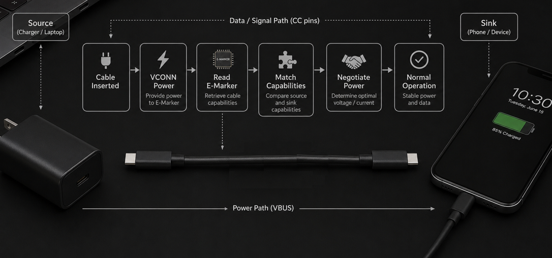
From the moment you plug in the cable until everything is working normally, the entire E-Marker process finishes in just a few milliseconds, completely invisible to the user. It happens in seven clear steps:
Step 1: Cable insertion is detected
When you plug a USB-C cable into a device, the physical connection is made. The CC (Configuration Channel) pins inside the port make contact first, and the device immediately recognizes that a cable has been connected.
Step 2: Power is supplied to the E-Marker
E-Marker has no built-in battery and cannot work on its own. The device sends a low-voltage power supply called VCONN through the CC pin to power up the E-Marker chip. The chip then initializes and stands by.
Step 3: The device reads the cable’s identity
Once powered, the host device sends a dedicated read command through the CC channel. When the E-Marker receives the request, it sends back all the capability information stored in its memory.
Step 4: The device decodes the cable’s capabilities
The device receives and interprets the full set of parameters: how much current the cable can safely carry, what data speed it supports, whether it can carry video, whether it works with high-speed modes, and more.
Step 5: Three-way capability matching
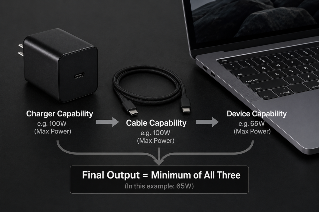
The device compares the maximum capabilities of three parties: the charger, the cable, and the receiving device. It then sets the working level to match the weakest of the three — this is the core rule for safe operation.
Step 6: Protocol negotiation is completed
Based on the matched capabilities, the devices finalize negotiation over USB Power Delivery (PD) protocol. They settle on charging voltage and current, data transfer speed, and whether to enable video output and other features.
Step 7: Normal operation begins
Once negotiation is finished, the cable enters stable operation: charging, transferring data, or outputting video. The CC channel continues to monitor the connection the whole time, and will adjust or disconnect if any abnormality is detected.
How E-Marker Communicates With Devices
You may wonder how such a tiny chip talks reliably with your devices. The communication logic is actually very straightforward.
3.1 Why use the CC channel for communication?
CC stands for Configuration Channel. It is a dedicated line inside the USB-C port made specifically for connection detection and feature setup. It does not take up bandwidth from the data lines, and it connects first when you plug in the cable, so identification can start immediately.
3.2 Why VCONN power is required
E-Marker is a passive chip — it has no battery and cannot draw power from the main charging lines. It must receive VCONN power from the device through the CC pin to turn on. This works the same way as a transit card or keycard that gets powered by the reader.
3.3 Who starts the conversation?
The device always takes the initiative. E-Marker only responds when queried; it never sends information on its own. It simply waits passively for a request and then replies with its parameters.
3.4 No conflict with normal communication
Normal PD charging negotiation between devices uses standard PD messages. Reading E-Marker information uses a special message format called SOP’. Only the E-Marker chip responds to this special format, so normal device-to-device communication is never affected.
3.5 How reliable communication is guaranteed
To ensure accurate identification, data on the CC channel uses BMC (Bi-Phase Mark Coding) transmission, and every data packet includes a CRC32 checksum. Like a tracking number on a package, this prevents errors during transmission.
What Information Is Stored Inside E-Marker?
Despite its tiny size, E-Marker stores a complete set of information covering every aspect of the cable’s performance.
4.1 Power delivery capabilities
This is one of the most important sets of data. It includes the maximum current the cable supports (commonly 3A or 5A), whether it supports USB PD 3.1 EPR (Extended Power Range), and the corresponding maximum power level (60W, 100W, 140W, 180W, 240W, etc.).
4.2 Data transfer capabilities
It records the data speed rating of the cable: from basic USB 2.0 (480Mbps), up through USB 3.2 (5Gbps / 10Gbps / 20Gbps), to USB4 (40Gbps) and USB4 Version 2.0 (up to 80Gbps).
4.3 Special feature support
It notes whether the cable supports USB Power Delivery, DisplayPort Alt Mode video output, Thunderbolt 3 / Thunderbolt 4 compatibility, and other advanced features.
4.4 Product identity information
It also contains manufacturing details such as Vendor ID (VID), Product ID (PID), product revision, USB-IF certification status, whether the cable is active or passive, and cable length.
How E-Marker Affects USB PD Fast Charging
More often than not, when fast charging isn’t reaching its full speed, the E-Marker is the reason.
5.1 Why E-Marker must be read before high-power charging
This is a mandatory safety rule from USB-IF. High-power charging, especially 5A high-current modes, places strict demands on the cable’s wiring. The device must first confirm via E-Marker that the cable supports 5A before enabling high-power mode, to prevent overheating and overload.
5.2 What happens without an E-Marker?
If there is no E-Marker in the cable, the device will default to treating it as a basic 3A cable. Even if both the charger and phone support 100W charging, the system will automatically limit power to 60W (20V × 3A) as a safe default.
5.3 The core logic of charging negotiation
Actual charging speed follows the “bucket principle”: the final output capability equals the minimum value among charger capability, cable capability, and device capability. If any one link is weaker, it limits the overall charging performance.
How E-Marker Affects High-Speed Data Transfer
It’s not just charging — high-speed data and video features also depend entirely on E-Marker identification.
6.1 Why high-speed modes require cable identification
Technologies like USB4 and Thunderbolt place extremely strict requirements on cable shielding, impedance and signal loss. A basic charging cable simply cannot carry high-speed signals. Forcing high-speed mode would cause frequent disconnections, data corruption, and device recognition failures.
6.2 Identification results define feature limits
Based on the information returned by E-Marker, the device decides which speed level to enable: basic USB 2.0 for file transfer, USB 3.2 for fast external drives, or USB4 / Thunderbolt for external GPUs and displays.
6.3 What happens when the cable isn’t fast enough
If the cable doesn’t meet the device’s maximum requirements, the system won’t just stop working. It will automatically lower the transfer speed or disable unsupported features, prioritizing a stable basic connection.
Common Scenarios: See E-Marker in Action
Looking at everyday situations makes the real impact of E-Marker easy to understand.
Scenario 1: Why does my 100W charger only deliver 60W?
Your charger and phone both say they support 100W fast charging, but your cable has no E-Marker, or only supports 3A current. The system reads the cable capability and limits power to around 60W for safety.
Scenario 2: Standard 100W PD fast charging
The cable has an E-Marker that confirms it supports 5A high current. After the device verifies all three parties support it, USB PD negotiates 20V × 5A, and full 100W charging is achieved.
Scenario 3: 240W PD 3.1 ultra-fast charging
The E-Marker indicates support for PD 3.1 EPR (Extended Power Range). The device recognizes this and enters EPR mode, enabling up to 240W of ultra-high power delivery.
Scenario 4: USB4 high-speed transfer and video output
When E-Marker shows the cable supports USB4 or Thunderbolt, the device automatically enables 40Gbps or even 80Gbps high-speed mode, perfect for fast external SSDs, docking stations, and high-resolution external monitors.
Final Notes: What E-Marker Actually Does
Many people mistakenly think E-Marker is a switch that controls charging. That is not the case.
8.1 E-Marker does not control charging
E-Marker itself does not deliver power, does not control the charger’s output, and does not directly set the charging power. It is not a power switch or a voltage regulator.
8.2 What E-Marker actually does
Its only job is to store the cable’s true capability information, passively respond to device queries, and provide accurate, standardized data for power negotiation and feature configuration.
8.3 One-sentence summary
When you plug in a cable, the device supplies VCONN power through the CC pin to wake up the E-Marker, reads the cable capability data stored inside, then matches and negotiates capabilities with USB PD protocol to finalize charging power, data speed and video output. The whole process takes only milliseconds, and you’ll never notice it happening.