
1. Why Cable Internal Resistance Matters
If you’ve ever plugged in a brand-new 100W USB-C charger only to get slow charging speeds, or felt a cable get uncomfortably warm during use, the hidden culprit is almost always cable internal resistance.
Most shoppers only look at the printed power rating on the packaging — 60W, 100W, 240W — but few understand that resistance inside the cable determines how much power actually reaches your device.
High resistance creates invisible problems that get worse as charging power increases:
- Slower-than-advertised fast charging speeds
- “Low-power charging” warnings on USB-C laptops
- Excessive heat that wears out insulation and connectors faster
- Unstable high-speed data and video output
This guide breaks down what cable resistance is, how it’s tested, and how to use this knowledge to pick better, safer charging cables.
2. What Is Cable Internal Resistance (DCR)?
2.1 Core Definition
Cable internal resistance, also called DC Resistance (DCR), is the opposition a cable’s conductor creates when direct current flows through it.
Common units:
- Ohm (Ω): standard unit for resistance
- Milliohm (mΩ): 1 Ω = 1000 mΩ, used for low-resistance charging cables
- Microohm (μΩ): used for very large industrial power cables
2.2 Three Parts of Total Cable Resistance
Total resistance you measure on a finished cable comes from three sources:
- Conductor body resistance The largest contributor. It depends on what the wire is made of, how thick it is, and how long the cable is.
- Contact resistance Resistance created at USB-C plug pins, crimp joints, and solder points. Even a tiny amount of extra resistance here causes major heat at 5A charging currents.
- Structural resistance Minor resistance differences from stranding pattern, conductor layout, and surface plating.
3. How Resistance Causes Voltage Drop and Heat
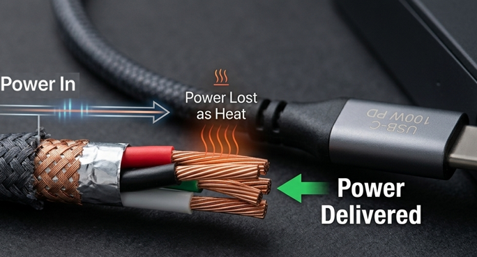
All resistance wastes energy, and that wasted energy turns into heat. Two simple formulas explain almost every charging cable problem.
3.1 Voltage Drop (IR Drop)
Formula: Vdrop = I × R
When current flows through resistance, voltage drops along the cable. That means the voltage that comes out of the charger is higher than the voltage that actually reaches your phone or laptop.
For example:
If you push 5A through a cable with 0.2Ω of total loop resistance, you lose 1V just in the cable. That’s 5W of power turned straight into heat instead of charging your device.
The result: Your device sees a lower voltage, so it pulls less power, and charging slows down.
3.2 Power Loss & Heat Build-Up
Formula: P = I²R
This is why high-power charging is so sensitive to cable quality. Power loss grows with the square of the current. Double the current, and you get four times the heat from the same resistance.
That’s why a cable that works fine for 15W phone charging can get dangerously warm when used for 100W laptop charging.
4. Why USB-C Fast Charging Demands Low-Resistance Cables
USB-C handles everything from 15W phone charging to 240W laptop power delivery. As power levels go up, cable resistance becomes more and more important.
4.1 The USB-C Power Path
Inside every USB-C cable there are two critical paths for power:
- VBUS: the positive power line that carries current to the device
- GND: the return path for current
Total loop resistance = VBUS resistance + GND resistance. This is the number that matters most for charging performance.
4.2 Power Levels & Resistance Expectations
- 60W (3A): Basic low-resistance design is sufficient
- 100W (5A): Requires tighter resistance control for safe, full-speed performance
- 140W (5A): Needs high-quality conductors and well-built connectors
- 240W EPR (5A): The strictest standards for conductor size, terminal quality, and overall resistance
4.3 What an E-Marker Chip Actually Does
An E-Marker chip is a tiny chip inside the cable that tells the charger what current and voltage the cable supports. It is required for all cables rated above 60W.
Important fact: An E-Marker only negotiates power capability. It does not lower cable resistance.
4.4 Why Your E-Marker Cable Still Charges Slowly
This is one of the most common user frustrations. You buy an expensive “100W E-Marker cable,” but charging is still slow.
The reason is simple:
The E-Marker chip correctly tells the charger “I support 5A,” but if the copper conductors inside are too thin or made of low-grade material, the actual resistance is too high to deliver full power.
The charger will try to send 5A, but heavy voltage drop forces the device to reduce its power draw. You get the protocol support, but not the real-world performance.
5. Common Cable Resistance Test Methods
5.1 2-Wire Resistance Test
How it works: The same two test leads both supply current and measure voltage. This is how a standard multimeter works.
- ✅ Pros: Simple, zero extra cost, works with any basic multimeter
- ❌ Cons: Includes the resistance of the test leads and probe contacts. Very inaccurate for milliohm-level low-resistance cables
- Best for: Checking if a cable is broken, rough side-by-side comparisons
5.2 4-Wire Kelvin Test (Industry Gold Standard)
How it works: Uses two separate pairs of wires. One pair (force lines) sends the test current. The other pair (sense lines) only measures voltage.
Because the sense lines carry almost no current, lead resistance does not affect the reading at all.
- ✅ Pros: Eliminates test lead error, measures milliohms accurately, repeatable results
- ✅ Used for: USB-C cable quality testing, factory QC, lab certification
5.3 Other Test Methods
- Micro-ohmmeter testing: Uses larger test currents for ultra-precise readings on thick industrial and automotive cables
- Electronic load testing: Simulates real charging conditions to measure actual voltage drop and temperature rise under real use
- All-in-one USB cable testers: Built for production lines; checks resistance, current rating, PD protocol, and E-Marker in one step
5.4 USB-C Cable Specific Test Points
When testing a USB-C cable, you should measure separate paths for different purposes:
- VBUS resistance: Main power line, most important for charging speed
- GND resistance: Return path, equally important for total loop resistance
- CC line resistance: Affects E-Marker communication and PD negotiation reliability
- Shield resistance: Important for EMI performance on high-speed data and video cables
6. Equipment for Cable Resistance Testing
6.1 Basic: Digital Multimeter
A standard household multimeter can tell you if a cable is open (broken) or roughly compare resistance between cables.
Limitations: Cannot accurately measure milliohm-level resistance. Results are reference only, not a final quality judgment.
6.2 Intermediate: Milliohm Meter / DC Low Resistance Tester
Built with 4-wire Kelvin measurement. Measures from micro-ohms up to tens of ohms with high accuracy. Most models include zero calibration and basic data logging.
Best for: Tech enthusiasts, repair shops, small-scale quality checks.
6.3 Professional: Integrated Test Systems
Full setups with micro-ohmmeters, programmable power supplies, electronic loads, and temperature sensors. Used in factories, certification labs, and R&D departments.
6.4 Essential Accessories
- Kelvin test clips for 4-wire measurements
- Isopropyl alcohol for cleaning connector contacts
- A temperature sensor for standardized result comparison
7. Step-by-Step Standard Test Procedure
7.1 Before You Start
- Fully disconnect the cable from all power sources and devices
- Clean connector pins to remove oxidation and dirt
- Check the cable for cuts, fraying, or damaged plugs
- Let the cable sit at room temperature long enough to stabilize
7.2 2-Wire Multimeter Quick Check
- Set your multimeter to the lowest resistance range
- Touch the two probes together and note the baseline lead resistance
- Touch probes to matching pins on each end of the cable
- Subtract the baseline to get a rough reference value
Note: This method has significant error. Use only for basic screening, not formal pass/fail judgment.
7.3 4-Wire Kelvin Standard Test
- Turn on the tester and let it warm up
- Short the Kelvin clips together and run zero calibration
- Clip onto both ends of the cable. Place sense clips inside the current clips, close to the conductor.
- Select an appropriate test current. Avoid very high currents on thin wires, which can heat the sample and skew results.
- Wait for the reading to stabilize, then record the value
- Write down the ambient temperature at the time of testing
- For formal comparison, convert the reading to the 20°C standard value
7.4 Temperature Correction Basics
Because copper resistance changes with temperature, engineers standardize resistance measurements at 20°C (68°F). This lets you compare tests done in summer and winter fairly.
For copper, resistance rises roughly 4% for every 10°C increase in temperature. For precise work, use the standard temperature coefficient of ~0.00393 /°C to convert readings.
8. Key Factors That Change Cable Resistance
8.1 Conductor Material
- Pure annealed copper: Lowest resistance, the gold standard for premium charging cables
- Tinned copper: Copper coated with a thin layer of tin to resist oxidation. Slightly higher resistance, better long-term durability
- Copper-Clad Aluminum (CCA): Cheaper to make. 30–50% higher resistance than pure copper. Not recommended for sustained high-power fast charging.
8.2 Conductor Size (AWG)
Rule of thumb: Smaller AWG number = thicker wire = lower resistance.
Common trap: A thick outer jacket does not mean thick copper inside. Many cheap cables use extra plastic to look heavy-duty while hiding thin conductors.
| AWG | Typical Use |
|---|---|
| 18 AWG | High-current USB-C power conductors |
| 20 AWG | Common in mid-to-high power charging cables |
| 22–24 AWG | Lower power charging and data signal wires |
8.3 Cable Length
Resistance increases linearly with length. All else equal, a 2m cable has about twice the resistance of a 1m cable.
Shopping tip: For maximum charging speed, pick the shortest cable that fits your needs.
8.4 Connector & Build Quality
Pin material, plating thickness, and crimp/solder quality all affect contact resistance. Poor workmanship often causes resistance to creep up after months of plugging and unplugging.
8.5 Wear & Aging
Repeated bending, pulling, oxidation, and heat break fine wire strands over time. As a cable ages, its internal resistance slowly goes up. This is why an old cable that used to charge fast can slow down over time.
9. How to Interpret Your Test Results
9.1 Reference Standards
Standards Relevant to Consumers
- USB-IF Type-C cable assembly specifications: Official performance requirements for USB-C cables
- IEC 60228: Global standard for conductor DC resistance limits
Industrial / Engineering Reference
- ASTM B8 / B193: Material standards for annealed copper wire
- UL 1581: General wire and cable test methods
Always compare results against both official standards and the manufacturer’s published specs.
9.2 Reference Resistance Values (Annealed Copper, 20°C)
| AWG | Approx. Resistance (mΩ per meter) |
|---|---|
| 18 AWG | ~21 |
| 20 AWG | ~33 |
| 22 AWG | ~53 |
| 24 AWG | ~84 |
9.3 Real-World Example: Good vs. Bad Cable
To see what resistance means in practice, compare two 1-meter USB-C cables at 5A charging:
| Cable A (Good Quality) | Cable B (Low Quality) | |
|---|---|---|
| Total loop resistance | 80 mΩ | 250 mΩ |
| Voltage loss at 5A | 0.4 V | 1.25 V |
| Power lost as heat | 2 W | 6.25 W |
Cable B wastes more than three times as much power as heat. In real use, it will charge slower, run hotter, and wear out faster.
9.4 Reading Abnormal Results
- Consistently high resistance: Usually means thin conductors, CCA material, or bad crimps/solder joints
- Fluctuating, unstable readings: Usually caused by dirty contacts, loose clips, oxidation, or electrical interference
10. How to Choose a Low-Resistance USB-C Cable
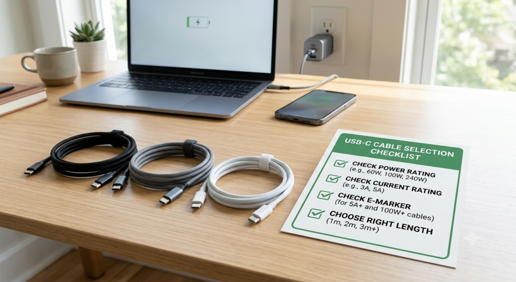
- Match power rating to your needs Check if you need 60W, 100W, 140W, or 240W. Higher power requires stricter resistance control.
- Check current rating 3A cables work for most phones; 5A is required for 100W+ laptop charging.
- Look for E-Marker on 100W+ cables Any cable rated above 60W should include an E-Marker chip. Remember: E-Marker is required but not enough on its own.
- Prefer shorter cables for maximum speed If you mostly charge at your desk, a 0.5m or 1m cable will always have lower resistance and better performance than a 2m one.
- Buy from trusted brands Reputable brands publish real electrical specs, not just marketing power numbers.
11. Common Myths & Troubleshooting Tips
11.1 Popular Misconceptions
❌ Myth: If the multimeter beeps on continuity mode, the cable is good.
✅ Fact: Continuity only means the wire is not completely broken. A cable with several ohms of resistance will still beep, but perform terribly at 5A fast charging.
❌ Myth: A thicker cable always has lower resistance.
✅ Fact: Thick outer plastic does not equal thick copper. Many budget cables use bulky jackets to hide thin, cheap conductors.
❌ Myth: A cable labeled 100W will always deliver 100W.
✅ Fact: The label tells you protocol support. Real performance depends on conductor size, material, and build quality.
11.2 Troubleshooting High Resistance
- Segment testing: Test each plug and the wire body separately to locate the high-resistance point
- Clean contacts: Scrub pins with isopropyl alcohol and retest to rule out surface oxidation
- Compare against a known-good cable: Test a reference cable of the same length and rating to confirm your test setup is working
12. How DCR Testing Connects to Cable Reliability
12.1 Temperature Rise Testing
Resistance creates I²R heat. Measuring DC resistance lets you predict thermal performance before running long-duration load tests.
12.2 Aging & Durability Testing
A gradual rise in resistance over time is an early warning sign that a cable is degrading.
12.3 Safety Testing
Excess resistance causes localized overheating, which can melt insulation and create fire hazards. DCR testing is a basic but critical safety screening step.
13. Frequently Asked Questions
Q: Can a regular household multimeter accurately test USB-C cable resistance?
A: No. Standard multimeters use 2-wire measurement and lack the resolution for milliohm-level readings. They work for checking if a cable is broken, but not for judging fast charging quality.
Q: What is a good resistance value for a USB-C fast charging cable?
A: There is no single universal number — it depends on length, wire gauge, and power rating. A high-quality 5A USB-C cable is typically designed with very low VBUS and GND resistance, and many manufacturers aim for a loop resistance around or below 200mΩ for 1-meter cables, depending on construction. Always reference official standards and manufacturer datasheets for formal evaluation.
Q: Why is my 100W E-Marker cable still charging slowly?
A: The E-Marker only tells the charger the cable supports high current. If the internal copper conductors are too small or low quality, high resistance will cause heavy voltage drop. Your device will then pull less power to compensate. Protocol support ≠ real-world performance.
Q: Does temperature make cable resistance go up or down?
A: Up. Copper has a positive temperature coefficient. Hotter copper has higher resistance. This is why cables get worse as they warm up during heavy charging.
Q: Why do I get different readings testing the same cable twice?
A: Common causes include dirty connector pins, inconsistent clip pressure, temperature changes, self-heating from test current, or electrical interference from nearby devices.
Q: How much worse is copper-clad aluminum vs. pure copper?
A: For the same wire gauge, CCA typically has 30–50% higher resistance. At 5A charging current, it runs much hotter and wastes far more power. It is not ideal for sustained high-power use.
Q: Can I test resistance on a cable that’s plugged in and powered?
A: Never. Testing a live cable gives wrong readings and can damage your meter or create a shock hazard. Always fully disconnect all power before testing.
14. Final Summary
- Cable internal DC resistance is the hidden factor that determines real charging speed and heat.
- High resistance causes voltage drop, wasted power, and excess heat. The effect gets much worse at higher charging currents.
- USB-C fast charging, especially 100W and above, relies on low-resistance conductors to deliver full power safely.
- The 4-wire Kelvin test is the industry standard for accurate low-resistance measurement.
- An E-Marker chip is required for high-power cables, but it does not lower resistance by itself.
- When shopping, don’t trust only the printed wattage rating. Look for reputable brands, proper current ratings, and appropriate cable length for your use case.