
If you have used USB-C devices, you have most likely encountered these confusions: even with the same oval USB-C connector, some cables can charge a laptop and connect to a monitor, while others can only charge a phone; when connecting a mobile hard drive to transfer files, the speed is as slow as a snail; even with the same cable, it works when inserted one way but has no response when inserted the other way. These problems seem varied, but the root cause is often hidden in the rows of tiny metal contacts inside the connector——that is, the pins of USB-C. This article will break down the USB-C pin definitions in detail from the perspectives of 24-pin layout, reversible insertion principle, functional logic, and practical applications.
1. Basic Understanding of USB-C Pins: First Figure Out What They Are and Why You Need to Learn Them
Before formally talking about pins, let’s clarify a few most easily confused concepts first, otherwise the more you read later, the more confused you will be.
First of all, USB-C (also called Type-C) is only a physical connector form factor——the oval connector that does not need to distinguish insertion direction. It itself is not equal to functional protocols such as USB 3.x, PD fast charging, USB4, or Thunderbolt. For analogy, the connector is like the shape of a parking lot entrance, pins are the lanes inside, and protocols are the traffic rules: the same entrance shape does not mean how many lanes are inside or how fast cars can go.
The pins we talk about (also called contacts) are the shiny small metal pieces inside the connector, which are the hardware channels for electrical signals to enter and exit. Pin definitions determine what signals the connector can carry——for example, whether there are power supply wires or high-speed data wires; while protocols determine how these signals communicate and how fast they run. For example, even with high-speed data pins, those supporting USB 3.2 can run at 10Gbps, and those supporting USB4 can run at 40Gbps. This is the difference in protocols, but if there are no high-speed pins at all, no matter how high the protocol is, it is useless.
There is another most easily overlooked pitfall: the final capability of USB-C never depends on the connector, cable, or device alone, but on the lowest level supported by all three. For example, if you have a Thunderbolt 3 laptop and use a cable with only USB 2.0, the maximum speed when connecting a hard drive can only reach USB 2.0; if you have a 100W charger and use a cable that can only carry 3A, the maximum charging power can only be 60W (20V×3A).
Why Does USB-C Have 24 Contacts
Many people are surprised when they look closely at a USB-C connector for the first time: why are there so many small contacts? A common USB-C receptacle (the recessed connector on the device) has a total of 24 contacts, two rows of 12 each on the top and bottom, arranged completely symmetrically. There are three main reasons for this design:
First, to realize reversible insertion. The upper and lower rows are mirror-layout, so no matter which way you insert it, you can touch the contacts with corresponding functions;
Second, there are many functions. USB-C needs to take into account power supply, basic data, high-speed data, video output, device identification and so many things, so naturally more channels are needed;
Third, to share high current. Multiple power supply and ground contacts are connected in parallel, which can reduce contact resistance, reduce heat generation, and carry greater power——just like multiple water pipes discharging water together, the flow rate is higher and it is less likely to be blocked.
Why Learn Pin Definitions
Knowing some pin definitions can solve most of your daily USB-C confusions: for example, why a cable can only charge but not transfer data, why there is no response when connecting to a monitor, why the speed is slower than others; when buying cables, you don’t have to just listen to the merchant’s “full-featured” bragging, you can judge by yourself whether it is a reduced-pin, cut-corner cable; you can also quickly distinguish USB-C devices that “look the same” and “have the same function”, and spend less wrong money.
2. Overall Layout of USB-C 24 Pins: Symmetrical Design and Function Grouping
Since pins are so important, let’s start with the overall layout to figure out how the 24 contacts are classified and arranged.
The following numbering and grouping are only for understanding the functional logic. The actual left-right order of rows A/B and pin numbers will vary depending on the observation perspective of plug/receptacle, front of the opening/soldering side. Do not directly use this for hardware design.
The 24 contacts of USB-C are usually divided into two groups, A and B. Taking the front view of the receptacle opening with the top row as group A and the bottom row as group B as an example, the two groups are vertically mirror-symmetrical——that is, A1 corresponds to B12, A2 corresponds to B11, and so on, exactly reversed.
Many people think that reversible insertion means the upper and lower pins are exactly the same and can be directly connected together, but that is not the case. Direction identification mainly relies on two dedicated pins, CC1 and CC2. After insertion, only one side of the CC will be connected to the plug. After the device detects it, it will switch the high-speed signal path through the internal circuit to ensure normal operation regardless of insertion direction. In short, symmetry is the appearance layout, and the real direction adaptation is realized through “detection + switching”, not simply connecting all pins together.
Tip: Ordinary users do not need to memorize specific pin numbers by rote; it is enough to know the logic of vertical symmetry and function grouping. If you are new to hardware design, you can refer to the functional schematic table below, and the actual design shall be subject to the official datasheet of the purchased connector.
Table 1 Functional Schematic Table of USB-C Receptacle (Front View of Opening, Only for Understanding Function Grouping)
| Group A Pins (Top Row) | Core Function | Group B Pins (Bottom Row) | Core Function |
|---|---|---|---|
| A1 | GND (Ground) | B1 | GND (Ground) |
| A2 | SSTX1+ (High-Speed Transmit 1+) | B2 | SSTX2+ (High-Speed Transmit 2+) |
| A3 | SSTX1- (High-Speed Transmit 1-) | B3 | SSTX2- (High-Speed Transmit 2-) |
| A4 | VBUS (Power Supply Positive) | B4 | VBUS (Power Supply Positive) |
| A5 | CC1 (Configuration Channel 1) | B5 | CC2 (Configuration Channel 2) |
| A6 | D+ (USB 2.0 Data+) | B6 | D+ (USB 2.0 Data+) |
| A7 | D- (USB 2.0 Data-) | B7 | D- (USB 2.0 Data-) |
| A8 | SBU1 (Sideband Auxiliary 1) | B8 | SBU2 (Sideband Auxiliary 2) |
| A9 | VBUS (Power Supply Positive) | B9 | VBUS (Power Supply Positive) |
| A10 | SSRX2- (High-Speed Receive 2-) | B10 | SSRX1- (High-Speed Receive 1-) |
| A11 | SSRX2+ (High-Speed Receive 2+) | B11 | SSRX1+ (High-Speed Receive 1+) |
| A12 | GND (Ground) | B12 | GND (Ground) |
Note: The transmit (SSTX)/receive (SSRX) direction of the high-speed differential pairs in the table is based on the host-side receptacle, and the direction is opposite on the device side. Different manufacturers may have different numbering due to differences in observation surface, plug/receptacle. PCB design must be based on the pin numbers and pad diagrams in the official datasheet of the purchased connector.
Overview of 24-Pin Function Grouping
Although there are many 24 contacts, they can be divided into six categories according to their functions. Here is a general table for quick understanding, and we will explain each one in detail later:
| Function Category | Core Pins | Main Function |
|---|---|---|
| Power Supply | VBUS, GND | Responsible for power input/output and current loop |
| Identification & Control | CC1/CC2, VCONN | Responsible for direction identification, power negotiation, cable capability detection, and power supply for chips inside the cable |
| Basic Data | D+/D- | Carries USB 2.0 data transmission, compatible with old devices |
| High-Speed Data | SSTX/SSRX (High-Speed Differential Pairs) | Carries high-speed signals such as USB 3.x, USB4, DP video, etc. |
| Auxiliary | SBU1/SBU2 | Video auxiliary channel, special accessory identification |
| Mechanical Shielding | Connector shell, fixing solder pins | Mechanical fixation, electromagnetic shielding, electrostatic discharge |
Note: VCONN is not an additional independent contact; it is usually powered by the CC contact on the side that is not used for CC communication.
It should be noted here that although mechanical shielding is not a signal pin, it is very important for the reliability and stability of the connector and cannot be ignored.
Full-Pin, Reduced-Pin and Fake Contacts
After understanding the grouping, you can understand a common “cost-cutting trick” in the industry: pin reduction.
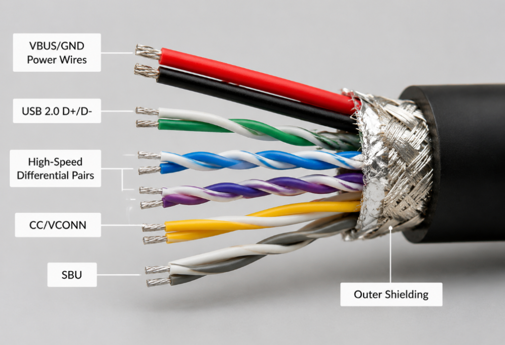
The so-called full-pin cables are those with all the contacts and internal wire pairs required for corresponding functions connected, which can support complete functions; while reduced-pin cables deliberately remove some pins that do not affect basic use in order to reduce costs, such as removing high-speed differential pairs, SBU, etc., and only retain power supply and USB 2.0 pins. Such cables can significantly reduce core wire, shielding and processing costs, but can only charge and transfer small files.
What’s worse is fake contacts: some low-cost cables look like they have 24 metal pieces on the connector, but they are not actually connected inside, just for show. So counting contacts by eye is useless; it must be judged combined with functional tests.
3. Plain-Language Detailed Explanation of Core Pin Functions
Next, we will explain the core pin functions one by one, trying to use plain language, so that you can understand what each pin does without knowing circuits.
1. Power Supply Positive VBUS
VBUS is the “main power line” in USB-C. All charging and power supply currents go through here, equivalent to the live wire of a household socket.
By default, when USB-C is just plugged in, VBUS outputs 5V voltage, the same as old USB connectors, to ensure compatibility. If the device supports PD fast charging, it will negotiate with the charger through the CC pin mentioned later to raise the voltage to 9V, 12V, 15V or even 20V. In USB PD 3.1 EPR (Extended Power Range), the maximum can reach 48V, corresponding to a maximum of 240W; actual availability depends on the charger, device, cable, and certification/marking.
Why are there several VBUS contacts? Because when there is high current, a single contact has small contact area, large resistance, and is easy to heat up. After multiple contacts are connected in parallel, it is equivalent to dispersing the current, which can not only carry larger current, but also reduce heat generation and improve reliability.
Here is a reminder: high-power charging never depends only on the charger; the device, cable, and charger must all support the corresponding power and current. For scenarios exceeding 60W, especially 100W/240W that require 5A current, cables with 5A and intelligent identification chips (commonly known as e-marker chips in the industry, used to report cable capabilities) are usually required; for within 60W, 3A cables are usually sufficient, but the final result still depends on the negotiation between the device and the charger.
2. Ground GND
GND is the ground wire, whose function is to form a current loop——current flows from VBUS to the device, then flows back from GND, forming a complete circle. At the same time, GND is also the “reference baseline” for all signals, just like the ground for measuring height; only when the ground is flat can the measured height be accurate.
Like VBUS, GND also has multiple contacts, whose functions are also to reduce impedance, reduce voltage drop, reduce heat generation, and also reduce interference between signals. If GND has poor contact, various strange problems will occur: such as intermittent charging, data transmission errors, frequent device disconnection, and even the connector getting hot. Whether it is power supply or high-speed signals, a stable GND is the foundation.
3. USB 2.0 Data D+/D-
D+ and D- are a pair of USB 2.0 data cables, which have existed since the old USB era. Almost all USB-C cables retain this pair of wires as the most basic compatible channel. Usually, when connecting a keyboard, mouse, USB flash drive, printer, or transferring small files of a few MB, this pair of pins is used.
But note that D+/D- can only support USB 2.0 speed at most (up to 480Mbps, theoretically converted to about 60MB/s), and the actual file copy speed is usually lower than this value, affected by protocol overhead, storage devices and system performance. Its existence does not mean that the cable supports USB 3.x or higher speeds. If you encounter the situation of “being able to charge but not transfer data”, it is most likely that this pair of wires is broken, or the corresponding contacts in the connector are dirty or damaged.
4. High-Speed Differential Pairs SSTX/SSRX
High-speed differential pairs are the “high-speed lanes” in USB-C. USB 3.x, USB4, Thunderbolt, and the main video signal of DP Alt Mode all go through these pairs of pins. Here is a common misconception to correct: USB-C does not have dedicated “video pins”, and video output is realized by multiplexing high-speed differential pairs. For common DP Alt Mode, USB4 or Thunderbolt video output, video usually cannot be output without high-speed differential pairs; a few dedicated display adapters are additional conversion solutions and cannot be understood as ordinary USB-C video capabilities.
USB-C has two sets of high-speed differential pairs on the top and bottom. When inserted reversibly, the device will switch to the corresponding set to work. High-speed signals have very high requirements for the path: the length of the two wires must be almost exactly the same, the impedance must be matched, and there should not be too many bends and vias, otherwise the signal will be messed up, the speed will not go up, or even the connection will fail directly.
5. Configuration Channel CC1/CC2
CC1 and CC2 can be said to be the “command center” of USB-C, and the entire “intelligence” of USB-C is realized by these two pins. Its main functions are four:
First, identify the insertion direction: after insertion, only one side of the CC is connected, and the device can judge whether you insert it forward or reverse by this, and then switch the high-speed signal path.
Second, negotiate power supply role and power: the charger and the device “talk” through the CC pin, telling each other how much voltage and current they can provide/need, and only after reaching an agreement will they adjust the VBUS voltage.
Third, detect cable capability: CC is responsible for building the PD communication link. Cables with e-marker will report 5A carrying capacity, voltage level, cable type and other information through PD communication. The specific reportable items depend on the cable specification and protocol version.
Fourth, enter special modes: such as DP Alt Mode, Thunderbolt and other non-standard USB modes, which are also negotiated to enter through CC.
In a standard USB-C connection, CC is the basis for insertion direction, role identification, PD negotiation, and Alt Mode entry. When CC is abnormal, fast charging, video, and high-speed modes usually cannot be negotiated normally, and some devices may only fall back to a very basic or non-standard state.
6. VCONN
Many people have not heard of VCONN. It is actually the power supply for electronic components inside the cable. You can think of it as the “salary” the connector pays to the cable: the e-marker chip in high-specification USB-C cables, as well as the circuits in active cables and active adapters, their working power is provided by VCONN.
The source of VCONN is very interesting: after insertion, the CC pin used for main communication (such as CC1 when inserted forward) is responsible for transmitting signals, and the other unused CC pin (such as CC2) will be switched to VCONN to power the chip inside the cable. Many people think that VCONN is a useless spare pin, but it is not——in scenarios where e-marker needs to be read or active cables need to be driven, without VCONN, the e-marker chip or active circuit of high-specification cables cannot work normally, and the device may not be able to confirm the cable’s 5A carrying capacity, voltage level or high-speed capability, thus refusing to enter high-power/high-bandwidth mode, or downgrading to a lower capability level.
7. Sideband Auxiliary Channel SBU1/SBU2
SBU is a sideband auxiliary channel, which is not used at all for ordinary USB data transmission. In most common DP Alt Mode implementations, SBU is often used to transmit auxiliary/control signals such as AUX and HPD; the main video data goes through high-speed differential pairs, and audio is usually embedded in the main link transmission along with the video protocol. Some special adapters and docking stations also use this pair of pins.
In short, SBU is a “standby auxiliary channel”, which is usually not used, but may be indispensable when doing video output or special functions. The specific usage depends on the protocol version and manufacturer’s design.
8. Shell and Shielding
Finally, let’s talk about the shell and shielding layer of the connector. Although it is not a signal pin in the traditional sense, its function is very critical: first, mechanical fixation, which makes the connector plug more stable and not easy to fall off; second, electromagnetic shielding, which blocks external electromagnetic interference and also prevents internal signals from leaking out, ensuring the stability of high-speed transmission; third, electrostatic discharge: when you have static electricity on your hands in winter, the first thing you touch when plugging in the cable is the shell, and the static electricity will be directly conducted to the ground, which will not burn the fragile chips inside.
4. Working Logic of USB-C Reversible Insertion: Why It’s Not “The Same on Both Sides”
After talking about the functions of each pin, let’s go back to the most curious reversible insertion: why can USB-C be inserted either way and work? Is it really that the upper and lower rows of pins are exactly the same? Actually no, its core is “symmetrical layout + CC detection + internal switching”.
Core Principle
Many people think that reversible insertion is to directly connect the corresponding upper and lower pins together, so that no matter which side you insert, it can be connected. That is actually wrong. For VBUS and GND of power supply, they are indeed connected according to specifications, because power supply does not distinguish direction, and connection can also increase overcurrent capability, which kills two birds with one stone. But for high-speed differential pairs, they must not be directly connected in parallel——high-speed signals are very sensitive to the path, and after parallel connection, signals will reflect and interfere, and cannot work at all.
So the real working logic is: after insertion, only one of CC1 and CC2 will be connected to the CC pin of the plug. After the device detects it, it knows the orientation of the plug, and then switches the high-speed signal to the corresponding row of contacts through the internal signal switch (also called MUX multiplexer) switch matrix. In this way, from the user’s perspective, both insertion directions work, but the internal actually does a “route switching”.
Processing Methods for Different Signals
Different types of signals have different direction processing methods:
- VBUS/GND: Power and ground contacts with the same name are usually connected according to specifications to form a stable power path and share current, while adapting to reversible insertion requirements; this processing method cannot be extended to high-speed signal pins.
- D+/D-: Because USB 2.0 has a low rate and low requirements for paths, it is usually not affected by direction, or only simple internal processing is required;
- High-Speed Differential Pairs: Must be switched to the corresponding side through internal switches to ensure the integrity of the signal path;
- Video/USB4/Thunderbolt: These all rely on high-speed differential pairs and protocol negotiation, so “being able to plug in” does not mean “being able to work with full functions”; all three, the device, cable, and monitor, must support it.
Judgment of Abnormal Reverse Insertion
For qualified USB-C products, the functions of both insertion directions should be completely consistent——if it can run 10Gbps when inserted forward, it should also be able to when inserted reverse; if it can trigger 100W when inserted forward, it is the same when inserted reverse. If only one side works, or the speed/power is different on both sides, it usually indicates an abnormality. Common causes include reduced pins of the cable (only one side of high-speed contacts is made), poor soldering of the connector, worn or oxidized contacts, or design defects of the device itself.
5. Pin Correspondence for Common Scenarios: Which Pins Are Used for Which Functions
You don’t have to memorize so many pins by rote. We correspond the most commonly used daily scenarios with the required pins, and you can directly compare them when encountering problems.
| Usage Scenario | Required Pins | Core Prerequisite | Common Fault Causes |
|---|---|---|---|
| Normal Charging/PD Fast Charging | VBUS, GND, CC | Device, cable, and charger all support the corresponding power; the power supply end usually only provides 5V before PD negotiation is completed | Failure to trigger fast charging is mostly due to CC negotiation failure or insufficient cable current |
| Connect Keyboard/Mouse/USB Drive/Transfer Small Files | VBUS, GND, CC, D+/D- | Compliant USB-C cables with D+/D- connected usually support it; charge-only cables, inferior cables, or damaged cables may not support data transmission | Being able to charge but not recognizing the device is mostly due to D+/D- damage, or the device end is set to charge-only mode/permission restriction |
| High-Speed File Transfer/Connect External Hard Drive | VBUS, GND, CC, High-Speed Differential Pairs | Both device and cable support the corresponding high-speed rate | Speed only at USB 2.0 level is mostly due to missing high-speed pairs or link negotiation downgrade |
| Connect Monitor/TV | VBUS, GND, CC, High-Speed Differential Pairs (some require SBU) | Device, cable, and monitor all support the corresponding video mode (such as DP Alt Mode) | No picture/abnormal resolution is mostly due to unsupported high-speed pairs, SBU, or protocol |
| USB4/Thunderbolt | High-Speed Differential Pairs, CC, VBUS/GND | Both device and cable support the corresponding protocol version; you need to check official specifications, port markings, protocol version, and cable certification, not just look at the USB-C appearance; not all 24 pins work at the same time | Failure to meet functional standards is mostly due to protocol mismatch or uncertified cables |
| Audio/Special Adapters | CC, SBU (some) | Accessory-specific solution, not a universal USB-C mode | Compatibility depends on accessory design |
Remember a core logic: the more complex the function, the more pins are needed, and the higher the requirements for cables and devices.
6. USB-C Connector Routing Logic: How Pin Definitions Affect Product Cost and Stability
Pin definitions not only affect cable functions, but also directly determine the difficulty of PCB routing, connector cost, and stability. The following explains from the perspectives of model selection, power supply, data, CC/VCONN, and shielding.
Many people are curious why the price of USB-C receptacles varies so much. The answer is hidden in the routing requirements corresponding to the pins——the more powerful the connector, the higher the routing difficulty and cost. Combined with pin definitions, entry-level designs can ensure basic stability as long as they avoid these core pitfalls:
1. Connector Selection and Package
USB-C receptacles are not of a unified specification. When selecting, you should first check the official connector datasheet to confirm whether the receptacle only has USB 2.0 pins, supports USB 3.x high-speed pairs, or is for higher-frequency applications such as USB4/Thunderbolt. At the same time, check whether the pad layout, shell ground pin, fixing pin, and board edge opening size match the design requirements. If you only need USB 2.0 and charging functions, a basic receptacle is sufficient; if you want to realize high-speed functions such as USB4 and Thunderbolt, you need to choose a high-specification receptacle with good high-frequency performance and controllable impedance. The price difference between low-cost connectors and high-specification connectors is obvious.
2. VBUS/GND Routing Logic
The width and thickness of VBUS traces should match the target current, just like the thicker the water pipe, the more water can flow. If the trace is too thin, it will heat up under high current, or even burn the board. GND should use a complete ground plane as much as possible, do not cut it into pieces, so that the current return path is the shortest and the interference is the smallest. For high-current areas, also pay attention to the number of vias. Do not use a single via to carry high current, which is easy to get hot.
3. D+/D- Routing Logic
This pair of wires should be routed as a differential pair——that is, the two wires are closely next to each other, with the same length as much as possible, fewer vias and fewer branches, and stay away from noisy places such as power switches and high-frequency clocks, otherwise they are easily interfered with and data transmission errors occur. It is best to add electrostatic discharge (ESD) protection devices next to the connector to prevent static electricity from damaging the chip.
4. High-Speed Pair Routing Logic
High-speed differential pairs have the highest routing requirements and are also the part with the largest cost difference. First, the differential impedance must be controlled according to the target protocol, and the lengths of the two wires must be almost exactly equal, with the difference not too large, otherwise the signals will not be synchronized. Also, try to have fewer vias and fewer branches, otherwise it will affect the signal quality. If the board is relatively large, or the signal travels far, you may need to add a signal compensation chip to amplify and shape the signal to ensure normal transmission. In addition, because reversible insertion requires switching high-speed pairs, a MUX switch chip is usually required. These are all reasons why full-featured connectors are more expensive.
5. CC and VCONN Routing Logic
CC pins cannot be connected casually; they must be matched with pull-up/pull-down resistors or a dedicated PD control chip to correctly identify the power role (power supply or power receiving), direction, and cable capability. VCONN must have a dedicated power supply path and overcurrent protection. It cannot be used as an ordinary power pin, otherwise it is easy to burn the chip inside the cable or the connector. ESD protection should also be added next to the CC pin, but the protection device should not have too large capacitance, otherwise it will affect the CC signal identification.
6. SBU and Shielding Processing Logic
If the product does not support video or special modes, SBU is usually processed according to the chip and connector reference design, can be left floating or reserved for protection, and should not be randomly connected to power, ground, or long branches; if it supports modes such as DP Alt Mode, the path should be kept short and straight, and matched with ESD protection. The shell and shielding layer of the connector should be grounded according to the electromagnetic compatibility (EMC) strategy of the whole machine. Some are directly connected to the main ground, and some are connected through capacitors or resistors, all for the purpose of reducing interference and electrostatic damage.
Common Routing Errors
The most easily overlooked pitfalls are: VBUS traces are too thin, resulting in large voltage drop and serious heat generation; CC pull-up and pull-down resistors are mismatched, resulting in unrecognized cables, no negotiation, or chaotic power supply roles; high-speed differential pairs have mismatched lengths and too many vias, resulting in unstable speed and only low-speed operation; ignoring ESD and shielding design, resulting in easy damage by static electricity, or occasional disconnection.
7. Practical Judgment Methods: How to Check the Pin Capability of Cables/Connectors
As an ordinary user, how to judge whether the pins of a cable or a connector are complete and whether there is cost-cutting? Here are some practical methods that can give you a rough judgment without disassembling.
Check Product Markings
Formal cables and devices will mark their capabilities:
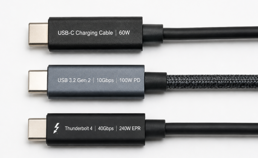
- Speed Markings: Such as USB 2.0, 5Gbps, 10Gbps, 20Gbps, 40Gbps. Speed markings represent the claimed or certified rate capability of the product, usually meaning the cable has corresponding high-speed channels and shielding design inside, but it still needs to be judged combined with certification level, cable length, active/passive type, and actual testing;
- Power Markings: 60W usually corresponds to 3A current capability, and most passive cables do not need a built-in e-marker chip; for 5A or EPR extended power scenarios such as 100W/240W, the cable usually needs to support the corresponding current/voltage level and report capabilities through e-marker or other methods. VCONN is mainly used to power e-markers, active cables, or active accessories, and cannot be simply understood as the higher the power, the stronger the VCONN design;
- Function Markings: For example, those marked with DP Alt Mode, Thunderbolt, USB4 indicate that they not only have high-speed pins, but also support the corresponding protocols, and can be used to connect monitors and docking stations.
Here’s a pitfall to avoid: if a cable is only marked as “USB-C charging cable” and does not clearly mark speed, video, or other functions, it usually only guarantees charging capability. Some retain D+/D- for USB 2.0 transmission, and some may not even have data wires connected; do not assume by default that it can support higher-level functions such as USB 3.x, video output, or USB4.
Actual Functional Testing
Appearance can be faked, but functions cannot:
- Data Test: Find an external hard drive or USB drive with USB 3.x or higher, transfer a large file of several GB. If the large file transfer is stably at USB 2.0 level speed for a long time, first suspect that the cable has no high-speed pairs, the connector’s high-speed contacts are abnormal, or the link negotiation is downgraded; you can further check the USB connection rate recognized by the system, or use a known USB 3.x/USB4 supported cable and port for cross-verification.
- Video Test: Find a monitor that supports DP Alt Mode, connect it with the cable, and see if the picture can be displayed normally, and whether the resolution and refresh rate can reach the nominal value;
- Fast Charging Test: Use a PD charger and a PD-supported device to see if the corresponding fast charging power can be triggered (can be measured with a power meter, or check the device’s charging prompt);
- Reversible Insertion Test: Be sure to test both sides to see if the functions are exactly the same. If only one side works, it is usually a problem of reduced pins or poor quality.
Check Connector Contacts
You can look at the contacts inside the connector against the light to see if there are 12 on the top and 12 on the bottom, totaling 24. But this method can only exclude those with obviously fewer contacts, and cannot deal with fake contacts——that is, it looks like there are metal pieces, but they are not connected inside. So the final judgment should still be based on functional tests.
Decision Logic for Choosing Cables According to Needs
You don’t have to blindly buy the most expensive full-featured cable, just choose according to your own needs:
- Only for charging mobile phones, connecting keyboard and mouse: ordinary USB-C charging cable or USB 2.0 cable is enough, no need to buy expensive ones;
- Need to transfer large files, connect high-speed external hard drives: choose cables that support USB 3.x (at least 5Gbps, preferably 10Gbps) or higher;
- Need to connect monitors, docking stations, USB4/Thunderbolt devices: choose full-featured cables, or cables with corresponding protocol certification (such as Thunderbolt certified cables);
- Need to fast charge laptops with power above 100W: prioritize cables marked with 5A, with e-marker, and clear power markings. Do not buy low-priced cables without clear specification markings or uncertified.
8. Common Misconceptions and Troubleshooting: Avoid Pin-Related Pitfalls
Common Cognitive Misconceptions
- Misconception 1: All USB-C connectors are 24-pin full-featured.
Truth: Many low-cost cables and devices have reduced pins, only retaining basic charging or USB 2.0 capabilities. Not all USB-C connectors support full functions such as high-speed data and video. - Misconception 2: The more USB-C pins, the better.
Truth: Pin configuration needs to match the usage scenario. Basic charging does not require all pins, while high-bandwidth scenarios must meet the corresponding pin and protocol requirements. - Misconception 3: USB-C can output 20V fast charging by default.
Truth: Standard products will first negotiate voltage through CC/PD, and usually only provide 5V before negotiation, and will not directly output high voltage. - Misconception 4: The thicker the USB-C cable, the stronger the function.
Truth: The thickness of the cable can only roughly reflect the power wire specification, and does not mean it has high-speed data pairs or shielding. The core depends on the internal wire pairs, shielding, and certification markings. - Misconception 5: It is normal for USB-C reversible insertion to work on one side but not the other.
Truth: Qualified USB-C products should have exactly the same functions for both insertion directions. Single-side usability is usually a quality problem caused by reduced pins, abnormal soldering, or contact wear.
Quick Troubleshooting of Common Faults
If you encounter problems, you can quickly locate them according to the corresponding relationship below:
- Can only charge but cannot transfer data: first check whether D+/D- are intact, whether the connector contacts are dirty, or whether the device is set to charge-only mode;
- Transmission speed is only at USB 2.0 level: first check whether high-speed differential pairs are missing (cable reduced pins), connector high-speed contacts are damaged, or link negotiation is downgraded;
- No picture when connecting to monitor, resolution cannot go up: first check whether high-speed differential pairs and SBU are normal, and whether the device and monitor support the corresponding video protocol;
- Fast charging cannot be triggered, only slow charging: first check whether CC negotiation is normal, whether the cable supports the corresponding current, whether there is an e-marker, and whether the charger and device support the corresponding PD protocol;
- Only one side works for reversible insertion: usually caused by reduced pins, abnormal soldering, contact wear or oxidation, which is not a normal phenomenon;
- Connector gets hot and disconnects frequently during charging: first check whether VBUS/GND contacts have poor contact, or the cable’s current carrying capacity is insufficient.
Study Summary
So far, the core knowledge of USB-C pins has been almost explained. To sum up, the core points are as follows:
First, the 24 contacts are divided into several categories by function: power supply, identification, basic data, high-speed data, auxiliary, and shielding. Among them, CC is the core of intelligent negotiation, and high-speed differential pairs are the basis of high-speed and video functions; VCONN is not an independent pin, but is provided by the reuse of CC contacts that do not undertake communication functions.
Second, reversible insertion is not realized by paralleling all pins, but by CC direction identification + internal MUX switching of high-speed paths. Qualified products should have consistent functions for both insertion directions; power and ground contacts are connected according to specifications to share current, but this treatment is not applicable to high-speed signals.
Third, different scenarios require different pins. The more complex the function, the more pins are needed. Choose cables according to your needs, and do not blindly pursue “full functions”; high-level functions such as USB4/Thunderbolt need to be judged combined with official markings, protocol versions, and cable certification, not just the connector appearance.
Fourth, to judge whether a cable has cost-cutting, first check the markings, then do functional tests, do not just look at the appearance and thickness; products only marked as “charging cable” usually do not guarantee high-level functions.
Fifth, USB-C connectors with different functions have great cost differences, which are essentially due to different routing difficulties and additional chips corresponding to the pins. Understanding these logics can help you better judge the actual value of a product.