
Have you ever had this experience: you bought a USB-C portable hard drive at a high price, but only get a speed of tens of MB/s when plugging it into your computer; you use the fast charging cable included with your phone to connect a monitor, but there is no signal at all; for USB-C ports of the same shape, some can connect to a dock to run a 4K display + Gigabit Ethernet, while others can only charge? In fact, the core of these problems is hidden in the TX/RX high-speed data channels inside USB-C.
Many people think USB-C is just an interface shape, but in fact, it contains multiple sets of pins with independent functions, and TX/RX is the core part responsible for high-speed data and video. This article starts from the most basic concepts, all the way to pin identification, reversible insertion principle, protocol correspondence, routing requirements, and common fault troubleshooting. After reading it, you will be able to understand 90% of USB-C high-speed related problems.
1. Core Entry-Level Concepts: What Exactly Are TX/RX
1.1 Plain Language Definition: TX Transmits, RX Receives, High-Speed Differential Signals Work in Pairs
TX (Transmit) is the channel that sends high-speed signals outward from the local controller or PHY (Physical Layer chip, responsible for high-speed signal transceiving processing); RX (Receive) is the channel that receives high-speed signals from the outside and sends them back to the local PHY.
Each group of high-speed channels is a differential pair composed of two wires, usually labeled P/N or +/-. It is critical to firmly establish this understanding first: these two wires are not the positive and negative poles of a power supply. The receiving end looks at the voltage difference between the two wires, not the voltage of a single wire to ground, which is also the core reason why differential signals have strong anti-interference ability.
TX/RX mainly carries high-speed signals such as USB 3.x, DP Alt Mode, USB4/Thunderbolt, etc. They are pins with completely different functions from VBUS power supply, CC configuration channel, USB 2.0 D+/D-, and SBU auxiliary channel, and cannot replace each other.
We can use a highway as a simple analogy: a pair of differential wires is like a one-way high-speed lane, TX is the lane driving out from your side, and RX is the lane driving in to your side. Only with one coming and one going can two-way communication be realized.
1.2 First Unify the Three Definitions of “Channel/Lane”
Many people get more confused the more they read materials, the core is that they do not distinguish between three commonly mixed “channel” concepts. We unify the definitions in advance, so that we will not be confused later:
The first is physical high-speed differential pair, which is the smallest hardware unit, that is, 1 pair of P/N wires, occupying 2 pins, usually carrying one-way high-speed signals, equivalent to a single one-way high-speed lane.
The second is USB 3.x full-duplex link, which consists of 1 pair of TX + 1 pair of RX, with a total of 4 high-speed pins, capable of sending and receiving data at the same time, equivalent to a complete two-way road section composed of two lanes (one coming and one going).
The third is DP/USB4/Thunderbolt lane. This type of protocol calls a one-way differential pair 1 lane according to its own rules, but the lane aggregation methods and bandwidth allocation logic of different protocols are different, and cannot be directly equated with the “1 group of full-duplex link” of USB 3.x.
It must be remembered here: do not treat “1 pair of differential wires”, “1 USB 3.x full-duplex link”, and “1 DP lane” as the same concept, otherwise it is easy to get confused when reading materials of different protocols.
1.3 The Same Physical Differential Pair Has Different Names in Different Protocols
The high-speed differential pairs in USB-C are “multiplexed”. The same physical线路 will assume different roles in different protocol modes, and their names will also change:
In USB 3.2 Gen1/Gen2 mode, it is 1 group of TX/RX full-duplex data link, dedicated to transmitting USB data;
In USB 3.2 Gen2x2 mode, 2 groups of TX/RX full-duplex links are used to aggregate two two-way road sections to run at a higher rate;
In DP Alt Mode, the high-speed differential pairs will be multiplexed into DP Main Link lanes, dedicated to transmitting video signals;
In USB4/Thunderbolt mode, the high-speed differential pairs will carry multi-protocol tunneling. Different types of traffic such as USB, DP, and PCIe are all packaged and transmitted on the same link, with dynamic bandwidth allocation.
In short, “the physical wires remain unchanged, they do whatever the protocol asks them to do”. We will elaborate on the specific occupation rules of each protocol later.
1.4 Three Core Applications of TX/RX
Although the functions of TX/RX high-speed channels seem many, the core is actually three categories:
The first category is high-speed data transmission, such as portable solid-state drives, high-speed capture cards, 2.5G/10G network cards, high-speed card readers, and high-speed USB flash drives. These devices that need to quickly transfer large files all rely on TX/RX to run at speed;
The second category is video output, which transmits display signals to monitors, projectors, and VR headsets through DP Alt Mode, USB4, or Thunderbolt;
The third category is multi-protocol expansion. For example, USB data, display, network port, card reader, and PCIe peripherals in a dock can all share bandwidth through the same group of TX/RX high-speed channels, without the need for separate wires for each function.
1.5 5 Core Misconceptions to Avoid for Beginners
People who are new to USB-C are most likely to fall into these pitfalls. We will clarify them in advance, which can avoid 80% of common misunderstandings:
- Misconception 1: All USB-C ports have high-speed TX/RX. No, many USB-C ports on mobile phones, chargers, and low-cost docks only have power supply and USB 2.0 connected, and there are no high-speed differential pairs at all, so naturally they cannot run at high speed.
- Misconception 2: If the interface shape is the same, the function is the same. USB-C is just the form of the connector. What it can do specifically depends on the internal controller, routing, cable, and supported protocols. The same shape does not mean the same capability.
- Misconception 3: The TX/RX direction is absolutely fixed. Both TX and RX are “relative to the local controller”. The labeling will change depending on whether the material you read is from the host perspective, device perspective, receptacle perspective, or plug perspective. You cannot memorize pin names by rote.
- Misconception 4: With high-speed pins, you can definitely run at high speed. Even if high-speed wires are soldered, it also depends on the PHY chip capability, cable quality, MUX switching, firmware support, and negotiation results. Failure in any link may cause speed drop.
- Misconception 5: Fast charging cables are high-speed cables. Power supply and high-speed data are two completely independent capabilities. A cable that can handle 240W may not have high-speed differential pairs connected at all, and can only charge but cannot transfer large files.
2. USB-C High-Speed Pin Definitions and Reversible Insertion Logic
Now that we understand what TX/RX is, let’s take apart the USB-C interface to see which pins these high-speed channels are hidden on, and why reversible insertion works.
First Principle for Reading Pin Diagrams: Confirm the Viewing Angle First
This is the first step that 90% of people get wrong when reading pin materials: the pin naming of USB-C will be completely different depending on whether you are looking at the receptacle (the concave port on the device) or the plug (the convex head on the cable), whether it is Top View or Bottom View, and whether it is from the host perspective or device perspective. For example, the pin labeled SSTX on the receptacle may correspond to SSRX on the plug, because the plug is flipped when inserted, and TX and RX will naturally cross.
So before reading any USB-C pin diagram, first find the viewing angle description in the title of the material. Do not just memorize pin numbers, otherwise it is easy to get them reversed.
High-Speed Pin Distribution and Function Division of the Receptacle
The following is the reference naming of the common USB-C receptacle front view (Top View, that is, the viewing angle when looking at the concave port on the device with pins facing up), adopting the USB-IF standard naming rules of SSTX1±, SSTX2±, SSRX1±, SSRX2±: there are 4 pairs of high-speed differential pairs in total, distributed on the A and B sides (that is, the upper and lower rows), among which A2/A3 and B2/B3 are SSTX related differential pairs, and A10/A11 and B10/B11 are SSRX related differential pairs.
Please note: this is only a reference for standard naming. Connector packages of different manufacturers, plug/receptacle viewing angles, and front/back viewing angles will all cause changes in pin correspondence. In actual design or schematic diagram checking, you must refer to the data sheet and package labeling of the specific device.
There is also a very important conclusion here: the SSTX/SSRX marked on the connector is not equal to the TX/RX of the PHY chip on your motherboard. Because it also goes through the mapping of cables, plug flipping, and high-speed multiplexer (MUX) in the middle, you cannot directly connect the chip according to the pin names of the connector, otherwise it will definitely not work.
In addition to high-speed differential pairs, other pins in the USB-C interface also have their own division of labor. The main ones related to high-speed channels are:
- VBUS: the main channel for power supply, only transmits electricity, does not carry high-speed data;
- GND: it is both the ground of the power supply and the reference return path for high-speed signals, which has a great impact on signal quality and is not dispensable;
- CC1/CC2: responsible for detecting whether the plug is inserted, whether the insertion direction is normal or reversed, and whether the roles of the two ends are host or device. It also carries USB PD communication, equivalent to the “command center” of the entire interface;
- D+/D-: the data channel of USB 2.0. Many USB-C ports that “can only transmit data at low speed” actually only have this group of wires connected;
- SBU1/SBU2: auxiliary channels, often used to transmit DP AUX auxiliary signals (such as EDID information of the display), and are not part of the high-speed main link.
Why Does Reversible Insertion Work? Switching Logic of Two Sets of Symmetric Channels
The biggest convenience of USB-C is that it works regardless of insertion orientation. The core of this function is that there are symmetrical high-speed contacts on both sides, plus the cooperation of CC pins and high-speed MUX.
The CC wire inside the USB-C plug only corresponds to the contacts on one side. When inserted, only one side of the CC1/CC2 on the host end can connect with the CC of the plug, thereby judging the insertion direction; if it is a cable with E-Marker, VCONN power will also be provided through the CC channel to read the cable capability. Here we first remember that the core is to identify the direction by CC. After determining the direction, the high-speed MUX (equivalent to a high-speed switch) will connect the corresponding group of high-speed differential pairs to the host’s PHY chip according to this direction.
In normal USB 3.x mode, usually only 1 group of TX/RX full-duplex link is enabled; while high-specification modes such as USB 3.2 Gen2x2, DP 4-lane, and USB4/Thunderbolt will use more high-speed differential pairs at the same time, even all 4 pairs. For a qualified USB-C interface design, the maximum speed, video capability, and stability of normal insertion and reversed insertion should be completely consistent. If the functions are different between insertion orientations, there must be a problem.
Complete Process of High-Speed Link from Insertion to Operation
Many people think that USB-C can work immediately after being plugged in, but in fact there is a complete negotiation process behind it:
The first step is physical connection. After the plug is inserted, pins such as VBUS, GND, and CC first form a basic connection, and power supply and detection are in place first;
The second step is direction and role detection. The CC pin judges the insertion orientation, and which end is the host (DFP) and which is the device (UFP), and at the same time confirms the default power supply capability;
The third step is channel switching. The high-speed MUX connects the corresponding high-speed differential pairs to the PHY according to the direction, and if necessary, also handles lane flipping and polarity flipping;
The fourth step is protocol entry. For ordinary USB 3.x, enumeration can start directly without PD; for DP Alt Mode, USB4, and Thunderbolt, it is necessary to negotiate capabilities through USB PD communication and switch to the corresponding mode;
The fifth step is link training. The PHY will communicate with the opposite PHY to adjust equalization, rate, and receiver parameters to ensure qualified signal quality. This process is like two people making a phone call, first adjusting the volume and speech speed to ensure that they can hear each other clearly;
The last step is system confirmation. The operating system recognizes the device, display, or dock, and the functions can be used.
If any step in this process goes wrong, situations such as only USB 2.0 remaining, repeated disconnection of the device, black screen of the display, and inconsistent functions between insertion orientations may occur.
Quick Method to Understand USB-C Pin Diagrams
If you get a USB-C schematic or pin diagram, you don’t need to understand all of it. Follow this order to find, and you can quickly judge the capability of this interface:
First look at the title of the material to confirm whether it is a receptacle or a plug, and whether it is a front or back view, otherwise it is all in vain;
Then find CC1/CC2: judge whether the hardware foundation for direction detection, role identification, and default current declaration is complete; but having CC pins does not mean that USB PD is necessarily supported. Whether PD negotiation is implemented also depends on whether there is a PD controller, firmware support, and official specification description, and cannot be judged only by pads;
Then find D+/D-. With this group of wires, it means that at least USB 2.0 data transmission is supported;
Then find SSTX/SSRX. With pads for high-speed differential pairs, it means that high-speed channels are routed — but note that this only means “routed”, and does not mean that it can really be used. It also depends on whether the other end is connected to the controller;
Then find SBU pins. Only with SBU is it possible to support the auxiliary channel of DP Alt Mode, otherwise video output cannot be used;
Then check if there are chips such as high-speed MUX, Retimer (signal retimer), and Redriver (signal redriver) nearby. Only with these can there be the capability of reversible insertion switching and high-speed compensation;
Finally, if possible, check the BOM table and complete schematic diagram to confirm that the high-speed differential pairs are not only drawn on the connector, but the other end is really connected to the high-speed pins of the controller — many low-cost devices only have the USB-C receptacle soldered on, with no wires connected to the high-speed pins at all; they look like they have pads, but they are actually just for show.
3. Basic Principles of High-Speed Transmission: From Understanding to Judgment
Many people think high-speed signals are “mysterious”, but in fact it is just because they are different from the “on-off” logic we are familiar with: low-speed signals can work as long as the wire is connected, while high-speed signals depend on whether the signal quality is good.
Why Is Differential Transmission Suitable for High Speeds?
We can use a simple analogy to understand the advantages of differential transmission: it’s like two people sending you messages at the same time, one saying positive words and the other saying negative words. You only need to compare the difference between the two to cancel out the noise on the way and hear the real content clearly.
Why must high-speed use differential? Because the higher the rate, the more times the signal changes per unit time, and the shorter the wavelength of the signal. A little interference or impedance discontinuity will deform the signal. Differential transmission uses two wires to transmit opposite signals, and the receiving end takes the difference, which can cancel most common-mode interference (that is, interference received by both wires at the same time), so it is more suitable for high-speed scenarios than single-ended signals.
But differential transmission is not “completely anti-interference”: if the line loss is too large, the signal reflection is too serious, the crosstalk of adjacent lines is too strong, or the contact is poor, it will also cause bit errors, or even make communication completely impossible. Whether a high-speed link can work depends on whether the eye diagram, jitter, loss budget, and link training can pass, not “whether the wire is conductive” — it’s just like a highway: being drivable is not enough; the road has to be flat and free of obstacles to run at 120 km/h, otherwise you can only go 60 km/h, or might not even dare to drive.
TX to RX: Crossover Logic of High-Speed Communication
The basic rule of high-speed communication is: the local TX must be connected to the opposite RX, and the local RX must be connected to the opposite TX. Just like making a phone call, your speech must be transmitted to the other party’s earpiece, and the other party’s speech must be transmitted to your earpiece. If connected reversely, you will definitely not hear.
In the USB-C system, this crossover is completed by the cable, connector, and high-speed MUX together: when the plug is flipped, TX and RX will naturally cross, and the MUX then adjusts according to the direction, finally ensuring that the TX and RX of both ends correspond. If you make your own PCB or modify the wire, you must look at the complete path: starting from the controller PHY, through AC coupling capacitors, ESD protection, MUX, connector, cable, opposite connector, all the way to the opposite PHY, whether the TX and RX of the entire path correspond. If the connection is wrong or the mapping is wrong, at best it cannot enter high-speed mode and can only recognize USB 2.0, at worst only one side of the insertion orientation works, and the link retrains frequently.
Link Establishment and Degradation from the Perspective of Signal Quality
Different from the process steps described in Chapter 2, from the perspective of signal quality, every step of the high-speed link is directly related to “whether it can run at full speed”:
In the physical connection stage, the cleanliness and contact resistance of the contacts will directly affect the signal amplitude. A dirty or loose interface may lay hidden dangers of instability from the beginning;
In the direction detection and channel switching stage, the insertion loss and return loss of the MUX will add extra burden to the link. A poor-quality MUX may directly “eat” half of the signal;
In the protocol entry stage, if there is a bug in the firmware logic of PD negotiation and Alt Mode switching, it may not enter high-speed mode at all;
The link training stage is the most critical: the PHY will repeatedly test different equalization parameters and rate levels until it finds the highest specification that can communicate stably. If the signal quality is not up to standard or the capabilities of both ends do not match, the degradation mechanism will be triggered: in USB data scenarios, it may drop from 10Gbps to 5Gbps, or even directly fall back to USB 2.0; in display scenarios, it may reduce the refresh rate, color depth, turn off HDR or reduce the resolution to ensure basic availability.
This is the core reason why sometimes the cable is not broken and the device is not broken, but it just can’t run at the nominal speed — it’s not that it can’t be used, but that the signal quality is not enough, so it can only run at a reduced speed.
Core Electrical Indicators Affecting Link Quality
If you encounter problems of high-speed instability or speed drop, it is essentially a problem with signal quality. There are several common influencing factors. You don’t need to memorize the parameters, just know the general meaning:
- Insertion loss: that is, how much the amplitude of the signal attenuates after passing through PCB, connector, cable, and adapter, equivalent to the sound becoming smaller when it travels far;
- Return loss: due to impedance discontinuity, the signal is reflected back when it encounters a “pit”. For example, connector pads, vias, and poor-quality adapters are all places where reflection is easy to occur;
- Crosstalk: noise from adjacent high-speed wires, other interfaces, or power supplies is coupled to the high-speed link, equivalent to someone making noise next to you, affecting your ability to hear clearly;
- Skew: the two wires of the same differential pair have different lengths, or the length difference between different lanes is too large, resulting in different signal arrival times, just like two people speaking out of sync, and the receiving end cannot align;
- Jitter: the edges of the clock and data are unstable. They should jump at a certain time point, but they are earlier or later. In severe cases, the “eye diagram” will close, and the receiving end cannot recognize the signal at all;
- Contact resistance: dirty, oxidized, loose, or worn interfaces will lead to poor contact, signals cannot be transmitted, and intermittent failures are also prone to occur.
Those “Seemingly Mysterious” Faults Actually Have Causes
Many people have encountered some unclear USB-C problems, for example, the same cable works on this computer, but drops speed when changed to another computer; or there is no problem in winter, but it is unstable in summer. In fact, these are not mysterious, they are all problems of signal quality behind:
- The same cable performs differently on different computers: because the PHY chip margin of different hosts is different, and the port routing and driver are also different, just like some people have good ears and can hear clearly even if it is a bit noisy, while some people have bad ears and cannot hear clearly with a little noise;
- The same dock performs differently when connected to different displays: because displays with different resolutions, refresh rates, and color depths occupy different bandwidths, 4K144 definitely occupies more bandwidth than 1080P60;
- Stability changes at low or high temperatures: cable loss, connector contact resistance, and chip equalization capability all change with temperature, and problems may occur when exceeding the range;
- The USB-C port on the front panel of the chassis is unstable: because there is an extra section of wire and a connector from the motherboard to the front panel, which additionally increases loss and reflection, so the signal quality is naturally not as good as the direct-connected port on the back of the motherboard.
4. Correspondence Between TX/RX and Various High-Speed Protocols
The high-speed differential pairs of USB-C are multiplexed. Different protocols occupy different numbers of channels and work in different ways. We have compiled a comparison table for your quick understanding:
| Protocol/Mode | Number of High-Speed Differential Pairs Occupied (Common Scenarios) | TX/RX Configuration | Whether USB 3.x High-Speed Data Is Retained | Typical Scenarios |
|---|---|---|---|---|
| USB 3.2 Gen1/Gen2 | 2 pairs (1 group of full-duplex) | 1 pair TX + 1 pair RX | Yes (it is USB data itself) | Portable hard drives, high-speed USB flash drives, capture cards |
| USB 3.2 Gen2x2 | 4 pairs (2 groups of full-duplex) | 2 pairs TX + 2 pairs RX | Yes (aggregated to 20Gbps) | High-end portable SSDs, flagship motherboard ports |
| DP Alt Mode 2-lane | 2 pairs | 2 pairs of one-way video channels | Yes (uses the remaining 2 pairs) | 4K60 video + high-speed data used at the same time |
| DP Alt Mode 4-lane | 4 pairs | 4 pairs of one-way video channels | No (only USB 2.0 retained) | High-specification video such as 4K144, 5K, 8K |
| USB4/Thunderbolt 3/4 | 4 pairs for common full-featured C-to-C links | Two-way dynamic bandwidth allocation, link can negotiate 20/40Gbps or higher, depending on host, cable, device, and protocol version | Yes (multi-protocol tunnel sharing) | Docks, multi-display, PCIe peripherals |
Relationship Between USB 3.x Speed and Channels
Many people can’t figure out the various versions of USB 3.x. In fact, the ones directly related to channels are these:
- USB 3.2 Gen1: the original USB 3.0/3.1 Gen1, with a link rate of 5Gbps, 1 group of TX/RX is enough;
- USB 3.2 Gen2: link rate 10Gbps, also supported by 1 group of TX/RX, and the current mainstream high-speed devices are basically of this specification;
- USB 3.2 Gen2x2: link rate 20Gbps, requires 2 groups of TX/RX aggregation, only supported by USB-C interfaces, commonly found in high-end portable hard drive enclosures and some motherboard ports.
Here is a special reminder: the nominal link rate is not equal to the actual file copy speed. Because encoding overhead, protocol overhead, file system, storage medium speed, and controller performance will all affect the actual transmission speed. For example, a 10Gbps portable SSD has a large file continuous read/write speed of about 700-1000MB/s, and a 20Gbps one is about 1500-2000MB/s, provided that the SSD itself and the hard drive enclosure controller are fast enough. If ordinary USB flash drive memory particles are used, it will definitely not run at full speed.
How to Judge the Video Bandwidth of DP Alt Mode
Many people encounter problems when connecting monitors, all because they can’t figure out the bandwidth rules of DP Alt Mode. Video capability does not only depend on “whether it can light up”, but depends on many factors: DP version, number of lanes, rate per lane, color depth, chroma format, refresh rate, whether there is DSC compression, and link quality.
In short, the 2-lane DP mode has the advantage of retaining USB 3.x high-speed data at the same time, but the video bandwidth is halved; the 4-lane DP mode has higher video bandwidth, but because all 4 pairs of high-speed differential pairs are used, there are no extra channels for USB 3.x, and only USB 2.0 can be retained.
There is also a common misconception: 4K60 does not necessarily require 4-lane DP. If it is DP 1.4 and supports DSC compression, 2-lane can also run 4K60 or even higher; but if it is DP 1.2, the color depth is 10bit, and HDR is also enabled, then 4-lane may be needed. High-specification displays such as 4K144, 5K, and 8K usually require 4-lane, a higher DP version, or DSC compression to support. If the bandwidth is insufficient, situations such as missing refresh rate options, inability to enable HDR, black screen, flickering, and automatic resolution reduction will occur.
Channel Characteristics of USB4/Thunderbolt
Both USB4 and Thunderbolt are multi-protocol tunneling technologies based on USB-C high-speed differential pairs. In short, they package traffic of different protocols such as USB, DP, and PCIe and transmit them on the same high-speed link, with dynamic bandwidth allocation.
Common USB4/Thunderbolt 3/4 link rates are 20Gbps and 40Gbps, and higher specifications such as 80Gbps of USB4 v2 depend on the implementation of the host, cable, and device. Note here: Thunderbolt 4 requires a minimum link capability of 40Gbps, but it does not mean that each downstream port of the dock can run at full 40Gbps independently — because the total upstream bandwidth is fixed, the display, USB, network port, card reader, and storage devices in the dock all share this upstream link. If you connect a 4K144 monitor, 2.5G network card, and portable SSD at the same time, the bandwidth allocated to each device will definitely decrease, and it is normal for the hard drive speed to drop.
The Upper Limit of Speed and Function Is Determined by the Shortest Board
In summary, the final capability of the USB-C high-speed link is determined by the lowest capability and the worst signal quality of all links in the entire path, that is, the cask effect:
- Host end: USB version, whether it supports DP Alt Mode/USB4/Thunderbolt, output capability of the graphics card, whether multiple ports share bandwidth;
- Peripheral end: capability of the bridge chip, speed of storage, DP version of the display, internal architecture of the dock;
- Cable: rate level, length, active or passive, whether there is E-Marker, certification level, power supply capability;
- Intermediate devices: adapters, extension cables, KVM, front panels, display conversion chips;
- System software: BIOS/firmware, chipset driver, graphics driver, operating system settings;
- Signal quality: PCB routing, connector quality, ESD devices, MUX/Retimer performance, contact status.
Failure in any link will lower the overall performance, so when encountering problems, don’t just blame a single device, check the entire link together.
5. PCB Routing, Cable, and Component Requirements for High-Speed Links
Many people will wonder: why are some USB-C cables only a few dollars, while others cost tens or even hundreds of dollars? Why can the rear port of some motherboards run at full 10G, but the front port can’t? The core is that high-speed TX/RX has very high requirements for routing, cables, and components.
Why Are High-Speed Channels So Sensitive to Routing and Cables?
The higher the rate, the faster the signal changes, and the more sensitive it is to loss, reflection, and crosstalk. You can understand it this way: low-speed signals are like shouting slogans, you can hear clearly even if the distance is a bit far and there is some noise; high-speed signals are like whispering, a little interference or a longer distance will make you unable to hear clearly.
The high-speed path of USB-C usually passes through the controller, PCB, MUX, connector, cable, and opposite device. In such a long path, any problem in any section may become a bottleneck. The longer the cable, the more times it is adapted, and the older the interface, the smaller the link margin, and a little fluctuation may cause speed drop or disconnection. The criterion for judging whether a high-speed link is good is never “whether the wire is connected”, but whether the signal integrity of the entire channel meets the requirements.
Core Rules of PCB Routing
If you are an ordinary user, you don’t need to delve into this part, just roughly know why it is designed this way; if you are a beginner hardware developer, these are the most basic requirements:
- Differential impedance: the target differential impedance of USB-C high-speed differential pairs is usually 90Ω, which shall be subject to the reference design of the chip and connector. Incorrect impedance will cause severe reflection;
- Length matching: the P and N wires of the same differential pair should be as consistent in length as possible to reduce pair skew; if it is a multi-lane design, the length difference between different lanes should also be controlled, otherwise inter-lane skew will occur;
- Reference plane: there should be a continuous reference plane (usually the ground plane) under the high-speed wires, and they cannot cross the division of power or ground, otherwise the impedance will be disordered and interference will be easily introduced;
- Routing topology: differential pairs should be routed in pairs, with consistent spacing, as few vias as possible, fewer sharp turns, and fewer branches, otherwise they will affect impedance and signal quality;
- Via control: minimize the number of vias. The stub of the via will cause reflection, and backdrilling or optimized stackup may be required in high-speed design;
- Escape routing: the fan-out area of the connector (that is, the section of wire coming out of the connector pad) is a hard-hit area of impedance discontinuity, which should be handled according to the recommended package and simulation results of the connector;
- Test points: do not add stub-type test points on high-speed wires casually, which can easily damage signal integrity. If you need to test, use stub-free test points or probe points;
- Polarity and lane mapping: some PHY chips support P/N polarity flipping or lane flipping, but not all chips support it. Be sure to check the data sheet before design, and do not take it for granted.
Selection and Placement of High-Speed Components
Each component on the high-speed path will affect the signal quality. The common ones are:
- AC coupling capacitor: usually placed on the path of the TX transmitting end to block DC. The capacitance value and position should be in accordance with the PHY reference design and protocol requirements, and cannot be selected casually;
- ESD protection device: used for anti-static, should select low-capacitance high-speed dedicated devices, and should be placed close to the connector, otherwise too large capacitance will also affect the signal;
- Common-mode inductor: can improve EMI (Electromagnetic Interference), but itself will introduce loss and impedance changes. It is not necessary for all designs, and should be selected according to the actual situation;
- High-speed MUX: responsible for reversible insertion switching and protocol multiplexing. It should be selected to match the target rate, and indicators such as insertion loss, return loss, and crosstalk must be sufficient, otherwise it will become a bottleneck;
- Redriver (signal redriver): equivalent to amplifying the signal and sending it out again, which can compensate for part of the loss, but cannot repair severe jitter and timing problems;
- Retimer (signal retimer): more capable than Redriver, it will restore the clock and data of the deformed signal again, equivalent to a signal relay station, usually used in USB4/Thunderbolt, high-speed docks, and long-link designs;
- There are also power supply and clock: the power supply noise and reference clock quality of high-speed PHY, MUX, and Retimer will also affect stability, and you can’t only pay attention to the signal wires.
How to Judge the Structure and Performance of Cables
Many people only look at the thickness and price when choosing cables, but these are not the key. Inside a full-featured USB-C cable, in addition to VBUS, GND, CC, and USB 2.0 wires, there are also high-speed differential pairs, SBU wires, etc.; while ordinary charging cables or USB 2.0 cables may not have high-speed differential pairs at all, so naturally they cannot transmit high-speed data or connect to monitors.
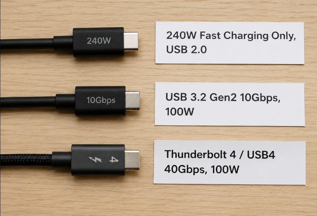
There are also many types of cable shielding structures, such as individual shielding, overall shielding, twinaxial cables, etc. You can’t think a cable is good just because it is thick or hard in appearance. The most reliable way to judge cable performance is to look at certification (such as USB-IF certification, Thunderbolt certification), nominal rate and protocol, and actual testing. Appearance, thickness, and price are only references.
It should also be noted that the internal wiring and capability declarations of C-to-C cables, A-to-C cables, USB4 cables, and Thunderbolt cables may be completely different. The capability span of common A-to-C cables is very large. Some only have USB 2.0, and some support 5Gbps or 10Gbps; however, since the USB-A form does not have the complete high-speed differential pair configuration and CC/Alt Mode negotiation mechanism required by USB-C, it usually does not support USB 3.2 Gen2x2, USB4, Thunderbolt, or USB-C DP Alt Mode passthrough. Do not confuse it with full-featured C-to-C cables.
Empirical Length Range of Different Cables
Many people ask “how long can a USB-C cable be”. There is no absolute answer to this, because it is related to the rate, cable quality, and host margin. Here is an empirical range for reference only:
- 5Gbps passive cables: common 1-3 meters are no problem, high-quality certified cables may be longer, and poor-quality long cables are prone to speed drop;
- 10Gbps passive cables: within 1-2 meters is relatively stable. If it exceeds, it depends on the cable quality and host margin;
- 20Gbps/40Gbps passive cables: usually within 0.8-1 meter is relatively stable, because the higher the rate, the greater the loss, and the higher the requirements for the cable;
- Active cables: built-in signal compensation chips, which can be extended to several meters, but some active cables have directionality or have requirements for protocols, so pay attention when buying;
- Optical USB-C/Thunderbolt cables: can achieve very long distances (tens of meters), suitable for professional scenarios, but expensive, and many optical cables have weak power supply capability, and compatibility also needs to be confirmed separately.
Still the same sentence: length is only empirical judgment, and whether it can run at full speed in the end depends on certification and actual negotiation results.
Functions and Misconceptions of E-Marker Chips
Now many high-speed cables or high-current cables mention E-Marker chips. Here we clarify its functions and common misconceptions:
E-Marker is a small chip built into the cable, which declares the capability of the cable to the host and device through the CC channel, such as how much current it can support, what type of cable it is, how high the rate it supports, whether it supports USB4/Thunderbolt, whether it is an active or passive cable, etc.
According to the specification, 5A high-current C-to-C cables must have E-Marker, because the default C-to-C cable can only support 3A, and 5A requires E-Marker to declare; high-specification cables such as USB4 and Thunderbolt usually also have E-Marker to declare their capabilities.
There are three very common misconceptions here, which must be noted:
First misconception: having E-Marker equals a high-speed cable. No, E-Marker only “declares capabilities”. Some cables’ E-Marker only declares 5A/240W power supply capability, and there are no high-speed differential pairs connected inside, so they can still only charge and cannot transmit high-speed data;
Second misconception: without E-Marker, you must not be able to transmit data. That’s also wrong. For example, many short, low-specification C-to-C cables, or A-to-C cables, may not have E-Marker, but can still support 5Gbps or 10Gbps rate, just can’t be required according to the standards of high-specification cables;
Third misconception: 240W cables can output video. 240W only indicates power supply capability, and has no inevitable connection with video output and high-speed data. Many 240W fast charging cables only have power supply and USB 2.0, and there are no high-speed channels at all.
So when choosing a cable, be sure to check the power, rate, protocol identification, certification mark, and length at the same time, don’t just look at the selling point of “240W” and place an order.
Effects of Adapters, Docks, and Front Panels
In addition to cables, intermediate adapter devices will also have a great impact on the high-speed link:
- Many low-priced adapters (such as USB-C to USB-A) only have USB 2.0 wires connected, and do not connect high-speed differential pairs at all, so naturally they can only run USB 2.0 when plugged in;
- Extension cables, magnetic connectors, KVM switches, and chassis front panels will add an extra section of cable and connector, bringing more loss and reflection. The higher the rate, the more obvious the impact;
- There are many chips inside the dock, such as Hub, DP conversion, network card, card reader, power supply control, etc. All downstream devices share the upstream bandwidth, and not every port can run at the maximum rate;
- HDMI/VGA adapters usually need to convert DP signals to HDMI/VGA, and the maximum resolution and refresh rate depend on the capability of the conversion chip, not that it can be used as long as it can be plugged in.
If you encounter high-speed instability, the specific troubleshooting can be carried out according to the unified process in Chapter 6.
6. Common Misconceptions and Fault Troubleshooting
This part is the most practical. If you encounter USB-C high-speed related problems, follow the methods below to check step by step, and most of them can find the cause.
General Troubleshooting Process: First Specifications, Then Negotiation, Then Variable Replacement
Many people change cables and devices as soon as they encounter problems, and can’t find the reason after trying blindly. The correct troubleshooting order should be like this:
The first step is to check the specifications first. Confirm the official specifications of the host, peripherals, cables, and docks, and whether they theoretically support the function you want. For example, if your computer’s USB-C port does not support DP Alt Mode at all, then you definitely can’t connect a monitor, and no matter how many cables you change, it’s useless;
The second step is to check the actual negotiated rate. Don’t just look at the nominal rate of the product, use system tools to see what the actual negotiated rate is. For example, if you think it is a 10Gbps device, but it actually only negotiates to 5Gbps, then it must be slow;
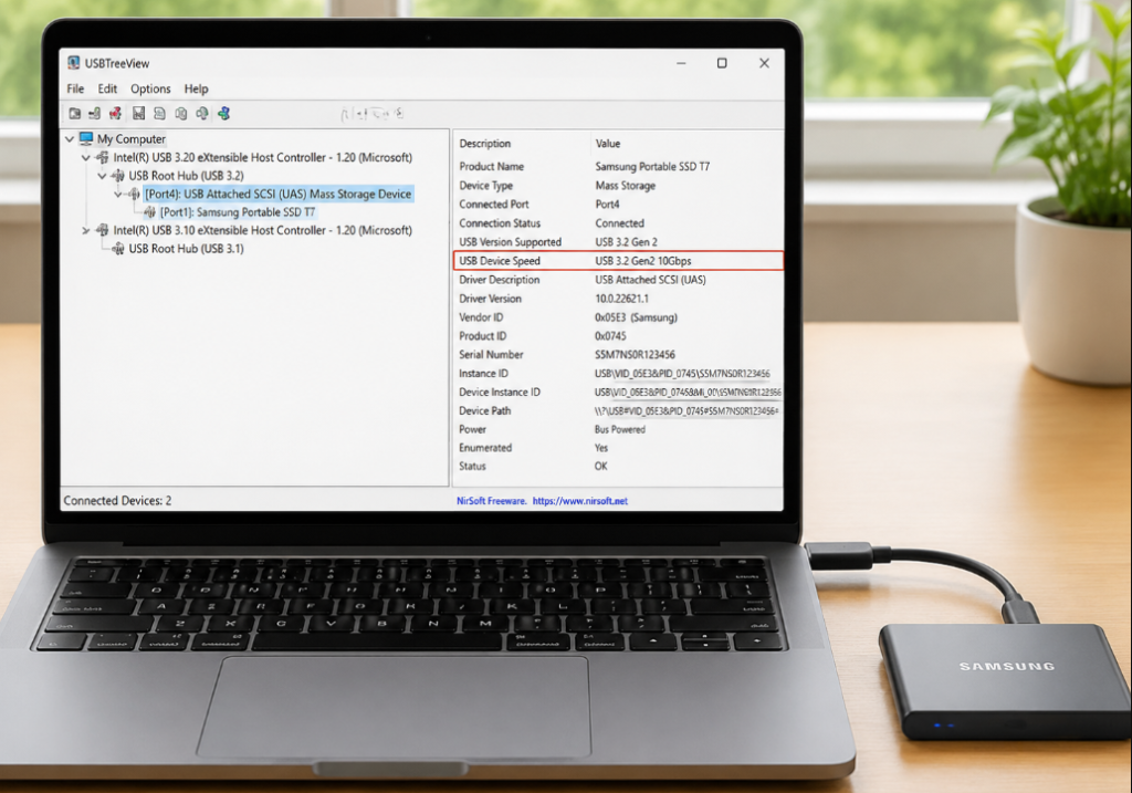
The third step is short cable direct connection test. Remove intermediate devices such as docks, adapters, extension cables, and front panels, use a short, certified cable to directly connect the host and the device, see if it works normally, and eliminate the problem of intermediate devices;
The fourth step is cross replacement of variables. Replace the host, cable, and peripherals respectively, see which device the problem follows, and you can locate which section has the problem;
The fifth step is hardware troubleshooting. If there are inconsistent functions between insertion orientations, disconnection with a light touch, or problems only with specific ports, then优先 suspect hardware problems with the connector, solder joints, MUX, or routing.
Summary of Advanced Usage Misconceptions
In addition to the 5 entry-level misconceptions in Chapter 1, there are several advanced common wrong cognitions, which are also clarified together:
- The more TX/RX pins, the faster the speed: No, it also depends on whether the protocol supports it, whether the controller can use it, and whether the cable is good enough. For example, if you have 4 pairs of high-speed differential pairs, but the device only supports USB 3.2 Gen2, then you can only use 1 pair, and the speed is still 10Gbps;
- All USB-C can connect to monitors: No, the host’s USB-C port must support DP Alt Mode, USB4, or Thunderbolt video output. Many ordinary USB-C ports only have data and power supply functions, and cannot connect to monitors;
- Each port of a 40Gbps dock can run at 40Gbps: No, the total upstream bandwidth is only 40Gbps, shared by all downstream devices. When more devices are connected, each device gets less bandwidth;
- Slow speed must be the problem of the hard drive: No, poor cables, insufficient ports, adapter speed drop, protocol degradation, and bandwidth sharing may all cause slow speed. Don’t blame the hard drive at the beginning;
- Different functions between insertion orientations are normal: No, a qualified design should have exactly the same function, speed, and stability for both insertion orientations. Differences must be a problem;
- If the monitor can light up, it means the bandwidth is sufficient: No, the system may automatically reduce the refresh rate, color depth, HDR, or chroma format. It can only light up, but does not reach the specification you want.
Root Causes of High-Speed Link Negotiation Failure
If your device cannot negotiate the highest rate, or simply can only run USB 2.0, the underlying reasons can be roughly divided into these categories:
- Physical layer problems: too long cables, too many adaptations, poor contact, oxidized contacts, loose connectors, these will cause signals to fail to transmit;
- Signal integrity problems: too large insertion loss, too poor return loss, too high crosstalk, too long via stub, impedance discontinuity, these will deform the signal, and the receiving end cannot recognize it;
- Channel mapping problems: wrong MUX switching for reversible insertion, wrong lane mapping, reversed P/N polarity, all will cause TX and RX to fail to align, and the link cannot be established;
- Component problems: too large capacitance of ESD protection devices, too high insertion loss of MUX, wrong configuration or insufficient performance of Redriver/Retimer, all will reduce signal quality;
- Protocol problems: PD negotiation failure, inability to enter Alt Mode, dock firmware problems, driver incompatibility, these software and protocol level problems will also cause high-speed functions to be unavailable;
- Power supply problems: insufficient power supply for peripherals or docks, for example, insufficient power for portable hard drives, will cause disk drop, repeated reconnection, and low speed.
Common Fault Troubleshooting Methods
We have sorted out the 5 most common faults, and each gives you specific troubleshooting steps:
Fault 1: Only Charging, No High-Speed Data Transmission
First confirm the port capability: whether the USB-C ports of the host and peripherals really support USB 3.x/USB4/Thunderbolt, many low-cost devices only have USB 2.0;
Then confirm the cable capability: whether you are using a charging cable or USB 2.0 cable, and whether there are high-speed differential pairs;
Then confirm the connection method: remove adapters, docks, magnetic connectors, etc., use a short cable for direct connection test, and eliminate the problem of intermediate devices;
Finally, check the actual rate: Windows can use USBTreeView or Device Manager, macOS uses the USB option in System Information, Linux uses lsusb -t, to see if the device is hung under the USB 2.0 or USB 3.x bus.
If only USB 2.0 devices can be seen, it is usually that the high-speed TX/RX is not connected, the cable is not supported, or the link training fails.
Fault 2: Transmission Speed Does Not Reach the Nominal Value
First, distinguish between link rate and actual file copy speed. A 10Gbps link rate is not equal to a stable speed of 1000MB/s. Encoding, protocols, and storage media all have overhead;
Then check the negotiated rate: see how much is actually negotiated, whether it has dropped from 10Gbps to 5Gbps, or directly fallen back to USB 2.0;
Then eliminate storage bottlenecks: if it is a mechanical hard drive, SATA SSD, or ordinary USB flash drive, its own speed is limited, and it will definitely not run at full interface rate. The controller of the hard drive enclosure and heat dissipation speed reduction will also affect the speed;
Also eliminate bandwidth sharing: if you connect a monitor, network card, card reader at the same time, or use a dock, then the upstream bandwidth is shared, and the hard drive speed will naturally drop;
When testing, try to use large file continuous read and write, test several times, first confirm the basic capability by direct connection according to the general process method, then add devices step by step, and see which step causes the speed to drop.
Fault 3: External Display Black Screen, Flickering, or Insufficient Refresh Rate
First confirm that the host port supports video output: whether there is DP Alt Mode, USB4 or Thunderbolt, otherwise you definitely can’t connect the monitor;
Then confirm that the cable supports the target display mode: use a full-featured USB-C cable, USB4/Thunderbolt cable or corresponding video cable that clearly supports the target display mode; you need to check whether the cable supports DP Alt Mode/USB4/TBT, the number of available lanes, length, certification level, and target resolution and refresh rate at the same time. You can’t just look at the nominal value of USB data rate, let alone use a charging cable or USB 2.0 cable to connect the monitor;
Then confirm the specifications of the dock or adapter: whether it supports the resolution, refresh rate, HDR you want, and whether there are system limitations (for example, some docks can only support single screen on M-series Mac);
Then check the display status: in the monitor’s OSD, system display settings, and graphics control panel, confirm whether the current resolution, refresh rate, color depth, HDR, and DSC are what you want;
If you are not sure whether the bandwidth is insufficient, you can first reduce the parameters and try, for example, reduce the refresh rate from 144 to 60, turn off HDR, reduce the color depth or resolution. If it becomes normal after reduction, then it is probably insufficient bandwidth.
Also note: if it is 2-lane DP + USB 3.x mode, the video bandwidth will be half less than 4-lane; if it is 4-lane video mode, usually there is no USB 3.x high-speed data, and only USB 2.0 can be used.
Fault 4: Inconsistent Speed or Function with Different Insertion Orientations
First make it clear: for a qualified design, the function, speed, and stability of normal insertion and reversed insertion should be completely consistent. Differences must be a problem;
There are many possible reasons: the contacts on one side of the interface are dirty, deformed, or worn, the high-speed wire on one side of the cable is broken or has poor contact, the internal MUX of the device has problems, the solder joints are loose, or the connector itself is broken;
When troubleshooting, you can flip both ends of the same cable for testing, see whether the problem occurs when flipping the host end or the device end, then change the cable, port, and device for cross verification, and you can locate which end has the problem.
Fault 5: Hard Drive Slows Down or Display Degrades After Connecting to a Dock
The core reason for this problem is that the upstream bandwidth of the dock is fixed, and all downstream devices share the total bandwidth. High-resolution, high-refresh-rate monitors will occupy a lot of DP/USB4/Thunderbolt bandwidth. If you connect MST multi-display, HDMI conversion, 2.5G network card, card reader, and external SSD at the same time, these devices will compete for bandwidth with each other, and it is normal for the speed to drop.
So when choosing a dock, don’t just look at the highest nominal value of a single interface, but look at the “simultaneous use specifications”, for example, whether it can run 4K60 + 10Gbps USB + Gigabit Ethernet at the same time.
When testing, you can first connect the hard drive alone to see what the speed is, then gradually connect the monitor, network port, and card reader, observe the speed change, and you will know which device occupies the bandwidth.
7. Purchase and Actual Measurement Methods for Ordinary Users
Now that we understand the principles and troubleshooting methods, let’s talk about how ordinary users choose devices and verify through actual measurement to avoid being misled by marketing slogans.
How to Judge the Port Capabilities of Hosts and Peripherals
First remember a principle: don’t just look at the shape of the USB-C interface, be sure to check the official specification sheet.
When looking for specifications, pay attention to these keywords: USB 3.2 Gen1, USB 3.2 Gen2, USB 3.2 Gen2x2, USB4, Thunderbolt 3/4, DP Alt Mode, these are the keys that determine the capability.
Also note: multiple USB-C ports of the same device may have different capabilities. For example, for some laptops, one USB-C port is Thunderbolt 4, and the other is only USB 3.2 Gen2 + power supply, which should be confirmed one by one.
Many mobile phones and tablets, especially low-cost or charging-oriented models, may only support USB 2.0 data and power supply; high-speed data, DP Alt Mode or USB4/Thunderbolt video output are bonus items, which must be confirmed by checking the official specifications per model.
There are also icons next to the interface, such as Thunderbolt logo, DP logo, battery logo, SS logo, which can only be used as a reference and cannot be used as the final basis. Everything shall prevail with the official specification sheet.
Quick Judgment of Cable Capabilities
When choosing cables, don’t just look at power, look in this order:
- If only 60W/100W/240W is marked: it mainly indicates power supply capability, and does not default to support high-speed data or video output, and it is most likely a charging cable;
- If 5Gbps/10Gbps/20Gbps/40Gbps is marked: it means it has corresponding data capability, and products with USB-IF or Thunderbolt certification