
Ever stuffed a USB-C or Lightning charging cable in your bag only to yank it out later and find the jacket split at the connector, or the terminal pulled clean out of the plug? If you’ve pulled electrical wire too hard during a home remodel and ended up with misaligned insulation and conductors, or dealt with a car wiring harness that failed mid-drive from vibration and strain, you’ve seen the effects of tensile load on cables firsthand.
While all these issues trace back to tension, most people don’t know how tensile performance is measured, what exactly is tested, or what counts as a passing result. Whether you’re trying to figure out if a cable is durable enough for your needs, verifying quality as a procurement specialist, or optimizing a product design as an engineer, understanding the basics of cable tensile testing is essential.
Important disclaimer: There is no universal pass/fail threshold for cable tensile performance. Acceptable values depend entirely on the cable type, applicable standard, construction, test conditions, and customer specifications. Applying a one-size-fits-all number across different products will almost always lead to incorrect judgments.
This guide is designed for three groups:
- Everyday consumers: Learn how to judge cable durability safely, without risky DIY destructive tests.
- Procurement and quality control teams: Use this to write clear acceptance requirements and verify test reports.
- R&D and engineering teams: Reference this to design test plans and conduct failure analysis.
Core Tensile Test Metrics and Their Use Cases
Now that we’ve covered basic concepts, let’s break down the most common tensile test metrics, what they measure, and when to use them. Never apply a metric designed for one scenario to a completely different use case.
Material-Level Mechanical Metrics
These metrics test the inherent properties of raw materials, such as copper conductors, insulation plastic, or jacket compounds:
- Tensile strength: The maximum tensile force per unit area, a core measure of a material’s inherent strength. Calculations use the effective cross-sectional area defined by the applicable standard, not arbitrary hand-measured dimensions.
- Elongation at break: The ratio of elongation at failure to the original sample length, expressed as a percentage. Higher values mean the material can deform more before breaking, and is less prone to brittle fracture. Note that high elongation at room temperature does not guarantee good low-temperature brittleness resistance—many plastics that are very flexible at room temperature become brittle in sub-zero conditions, so separate low-temperature testing is required.
- Yield strength, permanent deformation, and stress-strain curve: These metrics apply to materials with a clear yield point (such as copper). When pulled past a certain threshold, the material undergoes irreversible deformation; that threshold is the yield point. Permanent deformation is the amount of deformation remaining after the load is removed. A stress-strain curve plots the relationship between stress and deformation throughout the entire test. All of these metrics must be tested and evaluated per the relevant standard’s definitions.
Full Cable and Conductor Load Metrics
These are finished-product metrics tested on full cables or bare conductors:
- Common metrics include maximum force, break force, displacement, and permanent deformation. Maximum force is the peak tensile load recorded during testing, break force is the load at the moment the sample separates, displacement is the total travel distance during stretching, and permanent deformation is the residual deformation after the load is removed.
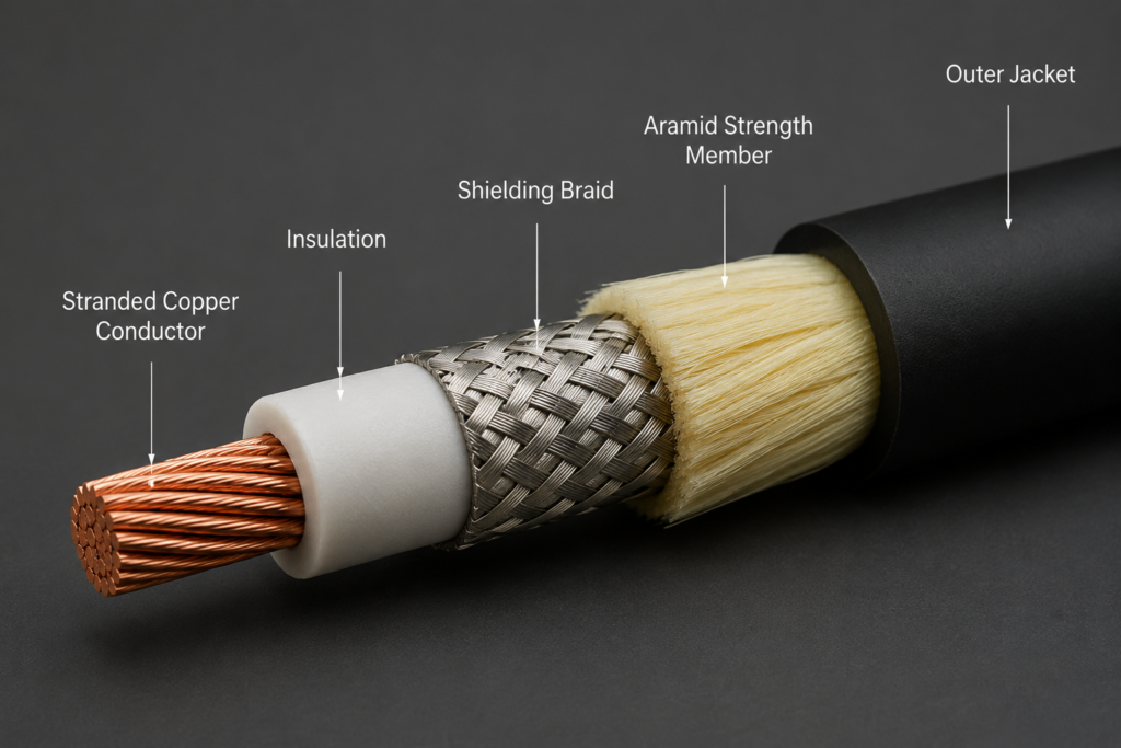
- A critical note: The tensile strength of a full cable cannot be directly equated to the tensile strength of its raw materials. Full cables are made of stranded copper conductors, and may also include shielding, braiding, and strength members (such as aramid/Kevlar fiber). When these components bear load together, the load transfer path is complex and not simply a sum of individual material strengths. For example, copper conductors of the same nominal cross-sectional area will have different break forces depending on whether they are solid or stranded. If a cable’s strength members are designed to carry most of the load and the grips effectively transfer load to those members, the full cable break force can be significantly higher than the load capacity of the copper conductor alone. If strength members only play a supporting role or load cannot be transferred to them effectively, their impact on full cable break force will be minimal.
Connection Reliability Metrics
These metrics test the connector end of the cable, which is the most common point of failure:
- Terminal pull-out force: The maximum force the crimped or soldered joint between conductor and terminal can withstand, the core metric for evaluating crimp or solder quality.
- Connector retention force: The maximum force the locking mechanism of mated connectors can withstand without separating, such as the pull-out force of a plugged-in USB plug. It evaluates the reliability of the connector’s latch.
- Conductor-insulation adhesion and jacket strip force: These measure the bond strength between insulation and conductor, and between jacket and inner cable core, respectively. They are separate test items evaluated per product construction and relevant standards.
Dynamic and Post-Environment Metrics
In real-world use, cables rarely experience only a single static pull. They may face repeated loading, or be used in extreme temperatures, humidity, or corrosive environments. These metrics more closely reflect real-world conditions:
- Cyclic tensile, bend, or drag chain cycle counts, and functional failure thresholds: These measure how many cycles of repeated loading or bending a cable can withstand before failing. Failure criteria must be defined in advance—for example, conductor break, intermittent contact, or insulation damage can all count as failure.
- Performance changes after exposure to high/low temperatures, humidity, corrosion, or aging: For example, a cable may be placed in a high-temperature environment for a specified time, then tensile tested to measure how much performance degrades.
- When evaluating “performance retention rate,” always confirm the baseline value, environmental conditions, treatment duration, sample state, and judgment criteria first. A “80% retention rate” alone is meaningless without this context.
Choose the Right Test Type for Your Use Case
Different cable applications require different tensile test types. Avoid using the same test plan for every cable.
Static Tensile Testing for Materials and Fixed-Installation Cables
For fixed-installation cables (such as residential wiring, buried, or in-wall cables), tensile test requirements are determined by product standards, installation codes, installation method, and actual load requirements. Test subjects can include conductor, insulation, or jacket material samples, or full cables, with different corresponding metrics. If you only need to verify the mechanical properties of the raw material, static tensile testing is used, with a focus on tensile strength, elongation at break, and failure location. Material sample test results cannot be directly equated to full cable load capacity, as the load-bearing structures are significantly different.
Terminal and Connector Testing for Finished Cables
For products like charging cables, power cords, automotive wiring harnesses, and connector assemblies, the most common failure point is the joint. For these products, focus testing on terminal pull-out force, connector retention force, jacket-to-core bond strength, and failure mode. For example, if a terminal pulls out, it matters whether the conductor broke inside the crimp or the terminal slid off entirely—different failure modes point to completely different root causes.
Dynamic Durability Testing for Moving Cables
For drag chain cables, robot cables, or cables that move frequently, a single static tensile test is not enough to reflect real service life. Based on the actual use case, combine tensile, bend, torsion, drag chain, and insertion/extraction testing. Focus on cycle count, load magnitude, movement speed, stroke length, bend radius, and functional performance during testing. For example, drag chain cables are tested to confirm they still transmit electrical signals normally after a specified number of drag chain cycles.
Environmental Coupling Testing for Harsh Conditions
If the cable will be used in harsh environments—such as outdoors, coastal areas, chemical plants, or extreme temperature conditions—first conduct environmental preconditioning, such as high/low temperature exposure, humidity testing, salt spray, chemical exposure, or thermal aging. After preconditioning, repeat the tensile test per the standard method to evaluate the magnitude of performance change. Pass/fail criteria for performance changes must be defined in advance, otherwise the test results have no reference value.
How to Select the Right Tensile Test Standard
One of the biggest challenges in tensile testing is choosing the right standard. Pick the wrong standard, and your test results may not meet your actual needs.
Common Standard Systems to Know
The most widely used standard systems fall into a few categories:
- International and regional standards: IEC (International Electrotechnical Commission), ISO (International Organization for Standardization), EN (European Standards), ASTM (American Society for Testing and Materials), UL (Underwriters Laboratories, US), CSA (Canadian Standards Association). Each system has its own scope of application and cannot be used interchangeably without verification.
- National standards: For example, GB/GB/T (Chinese national standards, where GB is mandatory and GB/T is recommended), or national standards of individual EU member states. Mandatory status depends on the specific standard and local regulations.
- Industry-specific specifications: Automotive, telecom, consumer electronics, marine, and mining products often have dedicated industry standards or customer-specific requirements, which are usually stricter than general standards.
4 Steps to Pick the Correct Standard
Use this general workflow to select the right standard for your test:
- Confirm target market, regulatory requirements, certification rules, and customer specs. Different countries and regions have different market access requirements. For example, US products often use UL, ASTM, or ANSI standards; EU products often use EN or IEC; and Chinese market products use GB/GB/T. Exact requirements vary by product category, so don’t just map a single standard system to an entire region.
- Confirm product type, voltage rating, construction, and use case. Different product categories have different dedicated product standards.
- Confirm test subject, method, loading rate, environmental conditions, and pass/fail clauses. Make sure the standard explicitly covers the test item you need.
- Check the current standard version, customer-specific requirements, and internal company standards. Many companies have internal control standards that are stricter than public standards.
Common Standard Use Mistakes to Avoid
Steer clear of these common pitfalls:
- Don’t use general material standards to judge finished products. For example, you can’t use a PVC material standard to pass or fail a finished charging cable—finished goods have their own dedicated performance requirements.
- Don’t assume a certification mark means a specific tensile test was performed. Certifications cover many test items, and it’s very common for them to only test electrical safety, not mechanical performance.
- If no applicable standard exists, define everything in writing. Write the full test plan, sample size, and pass/fail rules into the product specification, and get agreement from both the buyer and supplier. Only then will test results be meaningful.
How Professional Cable Tensile Testing Works
What does a professional tensile test actually involve, and what equipment is used?
Required Equipment and Fixtures
The core piece of equipment is an electronic tensile tester, also called a universal testing machine (UTM). Choose a machine with a load range, accuracy, and speed range that covers your test requirements to ensure accurate data.
Fixtures are equally important, and different test subjects require different fixtures: dedicated terminal fixtures for terminal testing, full-cable fixtures for whole cables, material sample fixtures for insulation or material tests, and non-slip fixtures to prevent slipping or jaw breaks (breaks at the clamp edge caused by grip damage) that invalidate results.
Optional accessories include:
- Extensometers, for precise deformation measurement
- Environmental chambers, for testing at high or low temperatures
- Continuity, insulation, and withstand voltage test equipment, to measure electrical performance during or after tensile testing
Test instruments must be used within their valid calibration or verification period, per applicable standards, laboratory management system requirements, or client agreements, with metrological traceability records retained. Measurement uncertainty evaluation should be conducted based on the report’s intended use and relevant specifications. Missing this information may mean the report cannot be used for standard compliance, laboratory accreditation, or specific use cases.
Sample Preparation and Preconditioning
Samples can’t be pulled randomly off a roll and tested. Batch, quantity, sampling location, and valid sample count must be determined per the standard or sampling plan.
When sampling, avoid cable ends, defective areas, and non-representative sections. Do not damage samples during preparation—for example, nicking the conductor while cutting the sample will skew test results.
Temperature, humidity, conditioning time, aging conditions, and sample gauge length must all strictly follow the relevant test standard to avoid result deviations caused by environmental conditions or sample preparation differences.
Standard Step-by-Step Test Procedure
A professional tensile test follows this general workflow:
- Define the test purpose, applicable standard, and pass/fail rules first—do not change requirements mid-test.
- Inspect equipment, fixtures, calibration status, and safety protections (e.g., confirm the e-stop works and safety shields are installed).
- Measure required dimensional parameters, such as wire diameter, cross-sectional area, and gauge length—these are the basis for all subsequent calculations.
- Mount and align the sample to avoid off-center loading. Adjust clamping force to prevent slipping without crushing or damaging the sample.
- Set pre-load, test speed, stroke, and stop conditions per the standard (e.g., stop at break, or stop at a specified force value).
- Record force-displacement data, failure location, and failure mode (e.g., break in the middle of the sample, jaw break, terminal pull-out, conductor break).
- After testing, recheck continuity, insulation, or other functional metrics to confirm the cable still works as required.
- Save raw data, photos, equipment information, and test reports for future traceability.
How to Interpret Test Results and Verify Reports
Once testing is complete, how do you know if the results are valid? And how do you read a test report thoroughly?
Key Calculations Explained
The two most commonly calculated metrics are:
- Tensile strength: Calculated as the maximum force (per standard definition) divided by the effective cross-sectional area. Cross-sectional area must be calculated per the standard—for example, standards have explicit rules for calculating the cross-sectional area of stranded conductors, so arbitrary measurements are not valid.
- Elongation at break: Generally calculated as the difference between the post-break gauge length and the original gauge length, divided by the original gauge length, expressed as a percentage. Gauge length and measurement method must follow the standard, as different gauge lengths will produce different results.
How to Tell if Test Data Is Valid
Not every measured value is meaningful. First, judge validity based on the test process and failure location. Invalid result rules vary by test type:
- Material tensile samples: If the break is outside the gauge length, at the jaw, or caused by obvious sample preparation damage, the strength and elongation data are generally considered invalid.
- Full cable tensile tests: If the sample breaks at the clamp, slips, or is loaded off-center, and the failure is not caused by the cable’s own load capacity, the results have no reference value.
- Terminal pull-out force tests: If failure occurs in the conductor outside the crimp area, or the terminal is deformed by the clamp, the results cannot be used to evaluate crimp quality. New samples must be prepared and retested.
- Connector retention force tests: If failure is caused by fixture damage or misalignment, rather than the lock mechanism’s own load capacity, the results should be discarded.
Additionally, confirm that invalid results are discarded per standard rules, and that retests are conducted per requirements—valid data must never be arbitrarily discarded. Note that you cannot judge pass/fail solely by “average value meeting requirements.” Some standards require every individual sample to meet the threshold, while others do not. Always follow the specific standard’s judgment clauses.
5 Dimensions of Pass/Fail Judgment
To determine if a product is up to spec, don’t just check if the number meets the threshold. Evaluate across five dimensions:
- Metric values: Do they meet the requirements of the specific standard or specification?
- Sample size and sampling plan: Do they meet requirements? For example, if the standard requires 10 samples, testing only 3 (even if all 3 pass) does not mean the batch is合格.
- Failure location and mode: Are the results valid? For example, if all samples break at the jaw, the data is useless no matter how high the force values are.
- Post-test performance: Do electrical and functional performance still meet requirements after testing? For example, if insulation is damaged and causes leakage after stretching, the cable fails even if the tensile force value is high.
- Test traceability: Are test conditions, equipment status, and data records complete and traceable? If not, you cannot confirm the test was conducted properly.
Test Report Verification Checklist
When you receive a test report, use this checklist to verify its reliability:
- Confirm client information, sample model, batch, quantity, and condition match the product in question, to avoid reports for different samples being passed off as valid.
- Confirm the applicable standard (and version), test location, test conditions, and method match your requirements, to avoid mismatched standards.
- Check that individual sample results, statistical methods, and pass/fail basis are included. A report with only an average value and no individual sample data is not sufficient.
- Confirm equipment ID, calibration status, laboratory accreditation, and report authorization scope are clearly listed. For example, verify the lab has accreditation for the specific test item.
- If needed, verify the lab’s accreditation scope, report number, and raw records to avoid fraudulent reports.
How to Set Appropriate Requirements for Different Cable Types
Different cable types have different performance requirements. Avoid applying requirements across unrelated product categories, as this will lead to incorrect judgments.
Home Wiring and Power Cables
Test items for these cables are determined by voltage rating, insulation material, product category, and current product standards. Focus on the material mechanical properties of conductors, insulation, and jackets, as well as allowable installation pulling tension limits, to avoid damaging cables during installation. Installation pulling tension requirements are usually defined by installation codes, design documents, or manufacturer technical specifications, and should be followed per the relevant documentation.
Network, Fiber Optic, and Telecom Cables
For these cables, distinguish between full cable tensile strength, connector retention, fiber protection, and transmission performance. Don’t just look at tensile force values—excessive tension can damage fiber cores or degrade transmission performance. Specific tensile force values must come from product standards, project specifications, or supplier datasheets, and cannot be set arbitrarily.
Charging, USB, and Consumer Electronics Cables
For these cables, distinguish between terminal pull-out, connector retention, bend fatigue, insertion/extraction life, and charging/communication function. Don’t only test tensile performance. Also note that marks like USB-IF or MFi do not guarantee that the specific tensile test you care about was performed. These certification programs have their own defined test scopes, which may not match your actual requirements—always check the specific test items and report content.
Automotive Harnesses and New Energy Cables
For these cables, select standards based on harness terminal type, charging system, automotive cable grade, and environmental rating. In addition to tensile testing, you must also verify crimp quality, terminal retention, thermal aging, vibration, bend performance, and electrical performance. The automotive environment is complex, with high vibration and temperature variation, so requirements are stricter than for consumer electronics.
Industrial and Specialty Cables
For drag chain cables, mining cables, marine cables, robot cables, and other specialty cables, cycle count, environmental requirements, and mechanical load requirements are determined by dedicated industry standards. Products with different constructions and use cases cannot be assigned the same cycle count or tensile threshold. For example, the performance requirements for robot cables and mining cables are very different.
What Consumers Can (and Can’t) Do to Check Cable Durability
Many everyday consumers want to test how tough a cable is on their own. Here’s what’s safe to do, and what you should never try.
Safe At-Home Checks
You can do these basic visual and functional checks with no special equipment:
- Inspect the jacket, connectors, and strain relief for cracks, bulges, looseness, or exposed conductors. If you see any of these, stop using the cable immediately.
- During use, watch for intermittent connections, unusual heating, charging dropouts, or unstable data transfer. These can all be signs of conductor or connector issues.
- Choose products from reputable brands with clear specs, applicable certification scope, and verifiable test information. Avoid no-name generic products with no branding, specs, or certification.
Tests You Should Never Try Yourself
These operations are unsafe or produce meaningless results, and are not recommended:
- Never hang heavy weights on a plugged-in cable for destructive testing. If the insulation is damaged, you risk electric shock.
- Don’t use DIY setups like water bottles or luggage scales to simulate professional testing. Loading speed, clamping method, and alignment will not meet standard requirements, so results will be inaccurate and potentially unsafe.
- High-voltage, high-current, EV high-voltage system, or specialty cable testing must be done by professional labs. Do not attempt these tests yourself.
Common Causes of Tensile Test Failures (and How to Fix Them)
What causes tensile test failures, and how do you address them?
Conductor and Material Issues
Undersized wire diameter, impure materials, defects in the wire drawing process, poorly designed stranding, subpar plastic formulation, extrusion process defects, or poor aging control can all cause tensile performance to fall below requirements.
Terminal and Connector Issues
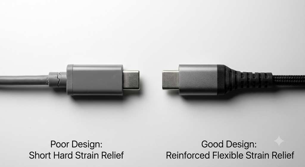
Incorrect crimp height (too loose = falls out, too tight = cuts the conductor), incorrect crimp width, mismatched terminal and cable size, oxidized conductors leading to poor crimps, defective lock mechanism design, or poorly designed strain relief can all cause low terminal pull-out force or connector retention force.
Dynamic and Environmental Performance Issues
Poorly designed stranding, too-small bend radius, low material fatigue resistance, inadequate sealing, or poor environmental protection can all cause fast failure in dynamic tests, or rapid performance degradation in harsh environments.
Basic Failure Analysis Workflow
When a test fails, first locate the break or pull-out point. Then use microscopy, cross-section analysis, dimensional rechecks, and electrical retests to narrow down the root cause step by step. Avoid randomly changing materials or processes without identifying the actual problem.
Actionable Checklists for Every Role
Different roles have different priorities. Use these checklists to put what you’ve learned into practice.
For Consumers
- When shopping, pay attention to connector and strain relief design. Prioritize products with soft, reinforced strain relief—cables with hard, unbuffered connectors are more likely to break.
- Check product specs and verifiable information, and avoid no-brand, no-spec, no-certification products.
- If you see exposed conductors, overheating, intermittent connections, or jacket damage, stop using the cable immediately and replace it. Don’t try to keep using a damaged cable.
For Procurement and Quality Control Teams
- When writing purchase specifications, clearly define the test subject, standard version, test conditions, sample size, and pass/fail rules to avoid vague language.
- When verifying test reports, check individual sample results, failure modes, lab accreditation scope, and raw data. Don’t take a “pass” conclusion as the only acceptance criterion.
- For critical batches, commission a third-party lab for retesting, or conduct on-site supplier audits to ensure consistent quality.
For R&D and Engineering Teams
- When validating products, test tensile performance alongside bend, torsion, aging, vibration, and electrical performance. Don’t validate tensile performance in isolation.
- Use failure data to iteratively improve materials, stranding design, crimp process, jacket construction, and strain relief design to boost product reliability.
Critical Tensile Testing Safety Tips
Safety is the top priority when conducting tensile testing. Follow these rules:
- Wear safety glasses, install protective shields, and maintain a safe distance from the machine. Confirm e-stop, limit switches, and fixtures are in good working order before starting the test.
- Never adjust samples or fixtures by hand while the machine is running. Flying broken samples can cause serious injury.
- For high/low temperature, high-voltage, or large cable testing, strictly follow dedicated safety procedures. Never cut corners on safety.
Frequently Asked Questions
We’ve compiled answers to the 10 most common questions about cable tensile testing:
1. What’s the difference between cable tensile testing and bend testing?
Tensile testing applies static or cyclic force along the axial (lengthwise) direction of the cable to measure load capacity. Bend testing repeatedly flexes the cable to measure bend fatigue life. They are completely separate test items and cannot replace each other.
2. Do home electrical wires need separate tensile testing?
Home wiring product standards usually specify mechanical properties for conductors, insulation, and jackets. Allowable pulling tension during installation is typically defined by electrical codes, design documents, manufacturer specs, or dedicated installation standards. For most residential use, standard product acceptance is sufficient. If the cable will be subjected to extra tensile load, add targeted testing based on your specific use case.
3. Is all tensile testing destructive?
No. If you’re testing allowable tensile load or permanent deformation, you stop the test at a specified force and the sample is not damaged—this is non-destructive testing. If you’re testing break force or elongation at break, you pull the sample to failure, which is destructive.
4. How do I choose the right UTM load range and fixtures?
Choose a load range based on the machine’s accuracy class, sensor range, standard precision requirements, expected maximum load, and safety factor. Make sure your test load falls within the machine’s valid measurement range to ensure accurate data. Pick fixtures based on the test subject’s type, size, and test item—for example, use dedicated terminal fixtures for terminal pull tests, and non-slip full-cable fixtures for whole cables. The core requirements are no slipping, no sample damage at the clamp, and aligned loading.
5. How do test speed, gauge length, and preconditioning affect results?
Faster test speeds usually produce higher tensile force readings, because the material does not have time to undergo plastic deformation. Longer gauge lengths generally produce more stable elongation at break results. Different preconditioning temperature, humidity, and settling times change material properties, which can lead to result deviations. That’s why all parameters must strictly follow the applicable standard.
6. How do I set test requirements if there’s no applicable standard?
If no existing standard fits your product, use similar product standards as a starting point, base requirements on real-world use cases, and negotiate with the supplier/buyer to reach agreement. Write the full test plan, sample size, and pass/fail rules into the product specification—once both sides agree, the test results will be meaningful.
7. How do I tell if a cable test report is complete and reliable?
Use the verification checklist we covered earlier: confirm sample information, standard version, test conditions, individual sample results, equipment calibration status, and lab accreditation are all complete and consistent. If you’re unsure, contact the lab to verify the report number.
8. How do I conduct failure analysis after a tensile test fails?
First, confirm the failure location and mode: did it break in the middle of the sample, at the terminal, did the terminal pull out, or did the conductor break? Then recheck dimensions like wire diameter and crimp height to see if they meet specs. Next, use microscopy to check for cross-sectional defects. Finally, combine with material analysis and electrical testing to narrow down the root cause step by step.
9. Why do you need to retest continuity and insulation after a tensile test?
Tensile load can cause partial conductor breaks or hidden insulation damage that is invisible to the naked eye, but that already reduces electrical performance. Retesting continuity and insulation ensures the cable still works safely and correctly after being stretched.
10. Can a certification mark prove tensile performance is up to spec?
No. Certifications cover many test items, and different certifications have different scopes. Many only test electrical safety and do not include mechanical performance testing. Never judge tensile performance by a logo alone—always check the corresponding test report.
Quick Glossary of Cable Tensile Testing Terms
If you’re new to tensile testing or working with global suppliers, these common terms will help you follow along:
- Cable Tensile Test / Cable Pull Test: A mechanical test that applies controlled axial load to a cable or cable component to measure strength, deformation, or failure behavior.
- Tensile Strength: A material-level metric equal to the maximum tensile force per unit cross-sectional area, measured in megapascals (MPa) or pounds per square inch (psi).
- Elongation at Break: The percentage increase in gauge length when a sample breaks, indicating a material’s ability to deform before failing.
- Terminal Pull-Out Force / Terminal Pull Force: The maximum force required to separate a conductor from its crimped or soldered terminal, used to evaluate connection quality.
- Connector Retention Force: The maximum force required to pull apart mated connectors, used to evaluate the reliability of the locking mechanism.
- Gauge Length: The specified length of the test sample (between clamps or marked on the sample) used to measure elongation.
- Tensile Test Speed / Strain Rate: The rate at which load or displacement is applied during a tensile test, specified by the applicable standard.
- Stress-Strain Curve: A graph plotting stress (force per unit area) against strain (deformation per unit length) over the full duration of a tensile test.
- Universal Testing Machine (UTM): A versatile mechanical testing machine used for tensile, compression, bend, and other mechanical tests.
- Grip / Fixture: The component of a testing machine that holds the sample in place during testing, designed for specific sample types and test methods.
At the end of the day, cable tensile testing is far more than just “pull until it breaks and write down the number.” The right test method and standard depend entirely on what you’re testing and how it will be used in the real world.
For everyday consumers, you don’t need to fixate on exact tensile force numbers. Focus on build quality: look for reinforced strain relief, durable jackets, and reputable brands with clear specs. Avoid DIY destructive tests, especially on plugged-in cables, and replace any cable that shows signs of damage.
For procurement and quality teams, the key is to write clear, specific requirements upfront and verify reports thoroughly—don’t just rely on a “pass” stamp or certification logo. Make sure data is traceable, sample sizes meet standards, and failure modes are valid.
For R&D and engineering teams, tensile testing only tells part of the story. Combine tensile testing with bend, torsion, environmental aging, vibration, and electrical performance testing to build cables that hold up to real-world use, not just lab specs.