
Meta Description: Learn what load regulation is, why voltage drops under load, and how to run a step-by-step load regulation test for USB-C PD and GaN chargers. Includes formulas, real-world examples, and troubleshooting tips.
Core SEO Keywords: load regulation test, power supply load regulation, USB-C charger stability test, USB PD charger testing, GaN charger performance test, voltage drop under load, how to test load regulation, charger voltage stability
Quick Answer (TL;DR)
Load regulation measures how stable a power supply or charger’s output voltage stays as the load current changes. For USB-C chargers, you should test each PD voltage profile separately, use a constant-current (CC) electronic load, and account for cable voltage drop. Typical consumer chargers show 1–5% deviation; high-quality models stay under 1%. Poor load regulation causes slow charging and unexpected device resets.
Quick Summary
- Load regulation measures how well a power supply keeps its output voltage steady when the load current changes.
- You can test it with basic tools or professional gear such as an electronic load and oscilloscope.
- Typical performance ranges from under 0.1% for precision linear supplies to 1–5% for consumer USB chargers. These are typical examples, not universal requirements.
- Poor load regulation causes slow charging, device resets, and unstable performance in high-power USB-C systems.
- The most common beginner mistakes are skipping warm-up and ignoring cable voltage drop.
1. What Is Load Regulation? Basics for Beginners
1.1 Core Definition
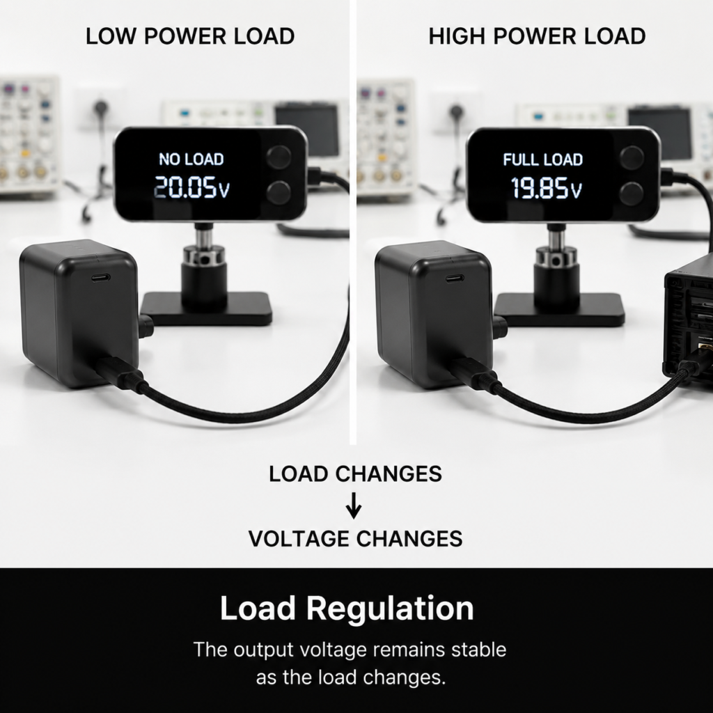
Think of your power supply like a household water tap. Open one tap slightly, and water pressure stays strong. Open every tap in the house at once, and the pressure drops noticeably.
Load regulation works the same way. It is the change in output voltage caused by varying load current, while input voltage, ambient temperature, and other conditions are held constant.
In plain terms: it tells you how stable your charger or power supply stays when your device draws more or less power.
1.2 Key Terms at a Glance
- No-load (V<sub>NL</sub>): Output voltage when the supply draws near-zero current.
- Full-load (V<sub>FL</sub>): Output voltage at the maximum rated current.
- Nominal voltage: The advertised output voltage (e.g., 12V, 20V).
- Rated current: The maximum safe current the supply is designed to deliver.
1.3 Easy Comparison: Load Regulation vs. Other Metrics
It is easy to mix up power supply specs. This table clears up the differences:
| Metric | What changes? | What stays fixed? | What it measures |
|---|---|---|---|
| Load Regulation | Output load current | Input voltage, temperature | Steadiness under changing power draw |
| Line Regulation | Input voltage | Output load, temperature | Immunity to wall-voltage fluctuations |
| Ripple & Noise | — | Steady load | High-frequency voltage “noise” on the DC output |
| Load Transient Response | Sudden load steps | Input, temperature | How fast voltage recovers after a load jump |
1.4 What Devices Need Load Regulation Testing?
Nearly every power device benefits from verification:
- AC-DC wall adapters and laptop chargers
- USB-C PD and GaN fast chargers
- DC-DC converter modules
- Linear regulators (LDOs)
- Industrial and medical power supplies
- Battery chargers and energy storage systems
1.5 Why This Metric Matters for Your Devices
Poor load regulation is not just a technical flaw — it causes real-world problems:
- Phones and laptops charge slower than advertised, or drop from fast-charge mode
- Sensitive electronics glitch, reset, or produce inaccurate readings
- Industrial controllers and stepper motors lose precision
- High-power devices trigger unexpected protection shutdowns
1.6 Why Modern USB-C Fast Chargers Care More About It
A decade ago, most USB chargers delivered 5V at 1–2A. Today, USB PD 3.1 extends power delivery up to 240W by introducing EPR (Extended Power Range) voltage levels, including 28V, 36V, and 48V, in addition to traditional SPR (Standard Power Range) levels of 5V, 9V, 15V, and 20V.
Higher power means bigger load swings. A 140W laptop can jump from 10W idle to 140W full load in milliseconds. GaN technology enables smaller, faster-switching designs — but tight control-loop design is required to keep voltage stable across these huge load changes.
2. Load Regulation Formulas & Calculation Examples
2.1 Formula 1: Percentage Based on Full-Load Voltage
This is one common industry convention, using full-load voltage as the reference:
Load Regulation (%) = [(V_No-Load − V_Full-Load) / V_Full-Load] × 100%
2.2 Formula 2: Percentage Based on Nominal Voltage
Many manufacturers and standards use the rated nominal voltage as the baseline:
Load Regulation (%) = [(V_Max − V_Min) / V_Nominal] × 100%
Where V<sub>Max</sub> and V<sub>Min</sub> are the highest and lowest voltages across the full load range.
2.3 Absolute Voltage Change
For quick engineering checks, you will also see it stated as a raw voltage difference:
ΔV = V_No-Load − V_Full-Load
This is useful for comparing supplies with the same nominal voltage.
2.4 Important Note: Datasheet Definitions Vary
There is no single universal formula. Manufacturers may define load regulation across:
- 0% → 100% load (no-load to full-load)
- 10% → 100% load (minimum load to full-load)
- Nominal load as the reference base
Always check which formula a test report uses before comparing numbers.
2.5 Hands-On Calculation: 12V Power Supply Example
Suppose you test a 12V DC power supply:
- No-load voltage: 12.10 V
- Full-load voltage: 11.85 V
Using the nominal-voltage formula:
Load Regulation = (12.10 − 11.85) / 12 × 100%
                = 0.25 / 12 × 100%
                ≈ 2.08%
2.6 Why Different Test Reports Can Show Different Results
If you see conflicting numbers for the same charger, the cause is almost always one of these:
- Different load ranges tested (e.g., 0–100% vs. 10–90%)
- Different reference voltage used in the formula
- Different test cables or ambient temperatures
- Measurement taken at the charger end vs. the device end
3. Test Equipment, Environment & Safety Preparation
3.1 Three Test Setups for Every Skill Level
You do not need a lab to get useful results. Choose the kit that matches your goals.
Beginner / Budget Kit
- USB-C power meter (plug-and-play voltage/current display)
- Compact USB electronic load (safer and easier than bare resistors)
- High-wattage power resistors (only if no electronic load is available)
- ⚠️ Safety warning: Power resistors get extremely hot during testing. Use heat-resistant mounts, avoid touching, and never leave energized resistors unattended.
- Alligator clips and short, thick test wires
- Best for: quick sanity checks, spotting obviously bad chargers
Intermediate / Hobbyist Kit
- Programmable DC electronic load (CC mode required)
- 4.5-digit or better desktop digital multimeter (DMM)
- Stable AC input source (or verified wall outlet)
- Optional: basic oscilloscope for transient checks
- Best for: serious hobbyists, repair shops, product reviewers
Professional / Lab Kit
- Automated test system (ATE) with power analyzer
- 6.5-digit precision DMM
- 4-wire Kelvin sensing / remote sense terminals
- Environmental chamber for temperature testing
- High-bandwidth oscilloscope for transient analysis
- Best for: R&D, certification, quality control
3.2 Standard Test Environment Requirements
For repeatable results, keep conditions consistent:
- Ambient temperature: ~25°C (room temperature)
- Stable input voltage (avoid long, thin extension cords)
- Low electromagnetic interference (away from motors, inverters)
- Proper grounding for safety and measurement accuracy
3.3 Device Under Test (DUT) Preparation
- Let the supply warm up at 50% load for at least 5 minutes to reach thermal equilibrium.
- Inspect connectors and terminals for dirt, corrosion, or looseness.
- Confirm the supply is rated for the full load current you plan to apply.
3.4 Critical Safety Rules
- Never exceed the DUT’s rated current or power.
- Double-check wiring before applying power; short circuits can destroy equipment.
- Use appropriately rated wires and connectors for the test current.
- Allow heat to dissipate; do not cover the supply during testing.
- Take extra care with AC-line side connections — high voltage is hazardous.
4. Step-by-Step Test Procedures
4.1 Pre-Test Checklist
- Input voltage set to nominal rated value
- Electronic load configured for Constant Current (CC) mode
- Voltage meter connected directly at the power supply output terminals
- Test leads and connectors rated for full current
- DUT has completed warm-up period
4.2 Basic Method: Static Load Regulation Test
This is the standard, industry-standard steady-state test.
Step 1 — Wire up and calibrate
Connect the DUT output to the electronic load. Connect your voltmeter directly across the supply’s output terminals (not at the load end). Zero or calibrate your instruments if needed.
Step 2 — Record no-load baseline
Set the load to 0 A (or the minimum specified load). Wait for the reading to stabilize according to the measurement instrument resolution and test requirement, then record V<sub>NL</sub>.
Step 3 — Step up the load and record each point
Increase load current in steps: 10%, 25%, 50%, 75%, 100% of rated current. At each step, wait for the voltage to settle fully, then log the voltage.
Step 4 — Verify reversibility by unloading
Ramp the load back down to no-load and record V<sub>NL</sub> again. The two no-load readings should match within ~0.5%. A large difference signals thermal drift or a faulty unit.
Step 5 — Calculate and document
Compute load regulation using your chosen formula. Save all raw data, test conditions, and equipment info for your records.
4.3 Standard Test Data Log Template
| Load Level | Load Current | Output Voltage | Notes |
|---|---|---|---|
| 0% (No-load) | 0 A | Baseline | |
| 25% | |||
| 50% | |||
| 75% | |||
| 100% (Full-load) | Max rated | ||
| 0% (Unload return) | 0 A | Reversibility check |
4.4 Advanced Test: Load Transient Response
Static load regulation tells you about steady-state performance. For devices with fast-changing loads (laptops, motors, communication gear), you also need dynamic response.
What it measures: How the supply reacts to a sudden jump in load current.
Key metrics to observe with an oscilloscope:
- Undershoot: How far voltage drops when load suddenly increases
- Overshoot: How far voltage spikes when load suddenly drops
- Recovery time: How long it takes voltage to return to within tolerance of nominal
How to run it:
Set the electronic load to pulse between 10% and 90% of rated current, with a controlled slew rate (typically 0.1–1 A/µs). Faster current transitions create larger voltage disturbances and require higher bandwidth measurement equipment. Capture the waveform on an oscilloscope across the output terminals.
4.5 Beginner Method: No Electronic Load? Use Power Resistors
If you do not have an electronic load, you can still get a rough result using power resistors:
- Calculate resistor values for your desired load current (R = V / I).
- Select resistors with adequate power rating (P = V × I, with at least 2x safety margin).
- Measure no-load voltage first.
- Connect the resistor load, wait for stability, then measure loaded voltage.
- Calculate load regulation normally.
Limitations: You cannot easily fine-tune load steps, and precision is lower. Heat can also change resistor values over time.
5. Testing Focus by Device Type
5.1 USB-C PD / GaN Fast Chargers (Special Focus)
Modern multi-voltage PD chargers require testing across each PDO (Power Data Object).
How PD Voltage Negotiation Works
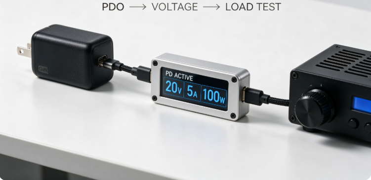
Before any load regulation test, the charger and sink go through a fixed sequence:
Charger announces available PDOs
        ↓
PD controller selects a voltage level
        ↓
Output voltage settles to the selected level
        ↓
Load regulation test begins at that fixed PDO
You must run a separate load regulation test for each PDO, as performance can vary significantly by voltage level.
Key test points:
- Test every fixed PDO separately: 5V, 9V, 15V, 20V (SPR) and 28V, 36V, 48V (EPR)
- Typical power tiers to validate:
- 65W: 20V @ 3.25A
- 100W: 20V @ 5A
- 140W: 28V @ 5A
- Confirm PD negotiation stays stable at full load — no renegotiation or dropouts.
GaN-specific notes:
GaN FETs enable higher switching frequencies and faster transient response, which generally helps load regulation. However, cheap designs with skimpy output capacitors or poor loop compensation can still perform poorly. Always measure, never assume.
5.2 Laptop & Desktop Power Adapters
- Focus on 20–100% load range (adapters rarely run truly no-load)
- Watch for thermal throttling after 10+ minutes at full load
- Verify barrel-connector or USB-C contact resistance does not add extra drop
5.3 Linear Regulators (LDOs)
- Typically excellent load regulation: 0.005% to 0.1% is common for precision parts
- Pay attention to dropout voltage at maximum load
- Very low ripple and noise compared to switching supplies
5.4 Switch-Mode Power Supplies (SMPS)
- Typical load regulation: 0.05% to 2% depending on quality
- Performance can change at light load if the supply enters burst mode
- Synchronous rectification designs generally have better full-load regulation
5.5 Industrial & Medical Grade Power Supplies
- Tighter tolerance requirements (often 0.5% or better)
- Must remain stable across wide temperature ranges
- Medical devices add isolation and safety constraints that can affect regulation
5.6 Battery, Energy Storage & Automotive DC-DC
- Wide input voltage range from battery state-of-charge changes
- Cold-crank and load-dump scenarios add extreme transient stress
- BMS and thermal protection can interact with load regulation
5.7 How USB-C Cables Affect Your Test Results
Cable resistance creates voltage drop that is often mistaken for poor charger regulation.
The rule: Higher current + longer/thinner cable = more voltage lost in the wire.
- At 5A (100W+), even 0.1Ω of cable resistance causes 0.5V of drop.
- E-Marker cables are required for 5A and higher currents.
- For accurate charger-only measurements, test at the charger’s output terminals, not at the end of a long cable.
6. Result Interpretation & Pass/Fail Judgment
6.1 Typical Performance Ranges (Reference Only)
These are real-world typical values — always use the manufacturer’s datasheet as the official pass/fail standard. These are typical examples, not universal requirements.
| Device Type | Typical Load Regulation Range |
|---|---|
| Precision linear / lab-grade supplies | 0.005% – 0.1% |
| High-quality industrial SMPS | 0.05% – 0.5% |
| Mainstream consumer SMPS / adapters | 0.5% – 2% |
| Budget USB-C chargers | 1% – 5% |
6.2 Three-Tier Judgment Rule
- Pass: Result is within the manufacturer’s published specification.
- Marginal: Slightly over spec (10–20% above limit). Usable for non-critical loads, but monitor for heat and long-term drift.
- Fail: Significantly out of spec, or causes visible problems (charging dropouts, resets, etc.). Investigate or replace the unit.
6.3 Reading Voltage-vs-Load Curves
Plotting voltage vs. current reveals more than a single percentage number.
Normal curve: Voltage decreases slowly and smoothly as load increases — a gentle, straight-ish slope.
Common abnormal patterns:
- Sharp drop at full load: Output power stage or capacitor is undersized.
- Oscillation / wavy line: Control loop instability, often at certain load ranges.
- Voltage rises with load: Almost always a feedback sensing error or wiring mistake.
6.4 How Protection Mechanisms Interact With Regulation
Load regulation is only valid within the supply’s normal operating range. Once protection kicks in, all bets are off:
- OCP (Over-Current Protection): If load exceeds the OCP threshold, voltage will collapse. Always test below the OCP trigger point.
- OTP (Over-Temperature Protection): After extended full-load operation, thermal throttling may reduce current or shut down the supply. Regulation specs assume normal operating temperature.
6.5 Real-World Curve Example
A well-behaved 20V PD charger might show:
- 20.05 V at 0 A
- 20.02 V at 25% load
- 19.98 V at 50% load
- 19.92 V at 75% load
- 19.85 V at 100% load
This is a smooth, gradual slope — about 1% total deviation, which is excellent for a consumer charger.
7. Why Voltage Drops Under Load: Key Factors That Affect Results
7.1 Power Supply Design & Components
- Control loop design: The feedback circuit’s speed and accuracy are the biggest single factor.
- Output capacitors: Low-ESR capacitors stabilize voltage during load steps.
- Reference voltage source: A precision bandgap reference sets the baseline accuracy.
- Power devices: MOSFET or GaN FET on-resistance contributes to full-load drop.
7.2 Test Cable Drop & Contact Resistance
Every wire and connector adds resistance. At high currents, even milliohms create measurable voltage loss. This is why you should always measure at the supply’s own output terminals.
7.3 Ambient Temperature & Component Heating
Semiconductor parameters drift with temperature. A cold supply will read differently than one that has been running for 15 minutes. This is why warm-up is mandatory for consistent results.
7.4 Input Voltage Fluctuations
If your wall voltage drifts during the test, you are mixing line-regulation effects into your load-regulation measurement. For best accuracy, use a regulated AC source or monitor input voltage continuously.
7.5 Warm-Up Duration
Most supplies drift slightly as they heat up. Testing too early gives you a “cold” reading that does not reflect real-world sustained performance. Five minutes at 50% load is a good minimum.
8. Common Beginner Mistakes & How to Fix Them
| Common Mistake | What Goes Wrong | Correct Practice |
|---|---|---|
| Measuring voltage at the load end of the cable | Cable resistance adds extra drop, making regulation look worse than it is | Measure directly at the power supply output terminals, or use remote sense |
| Skipping the warm-up period | Cold components give inconsistent, unrepeatable numbers | Run at 50% load for ≥5 minutes before recording data |
| Setting electronic load to CR mode instead of CC | Load resistance changes with voltage, distorting the test | Always use Constant Current (CC) mode for load regulation |
| Taking readings right after changing the load | You capture transient dip, not steady-state value | Wait until voltage stabilizes fully |
| Ignoring input voltage changes | Line variation gets mistaken for load regulation error | Monitor input voltage throughout the test |
Pro Tips for Better Accuracy
- Use the shortest, thickest test leads you can.
- For highest precision, use 4-wire (Kelvin) sensing.
- Repeat the test 2–3 times and average the results.
- Write down ambient temperature every time.
9. Troubleshooting: When Results Fail Spec
9.1 First: Check the Simple Stuff
- Loose or dirty connectors: Clean and re-seat all terminals.
- Wrong load mode: Confirm CC mode is active.
- Insufficient input power: Make sure the input source can deliver enough current.
- Test cable too thin: Swap in heavier-gauge leads and retest.
9.2 Advanced Diagnostic Checks
If basic fixes do not help, look deeper into the design:
- Output capacitors: High ESR or reduced capacitance is the #1 cause of poor load transient performance.
- Feedback network: Check resistor tolerance, drift, and solder joints.
- Reference voltage: Verify the voltage reference is accurate and stable.
- Loop compensation: Poorly tuned compensation causes oscillation and slow recovery.
9.3 Three Classic Failure Patterns
- Light-load voltage too high: Often means the minimum load requirement is not met, especially for some flyback SMPS designs.
- Severe full-load voltage drop: Usually undersized output capacitors, high-resistance power path, or current limiting kicking in early.
- Non-linear / erratic curve: Points to control loop instability, mode-switching artifacts, or thermal protection activating mid-test.
9.4 USB-C Fast Charger Troubleshooting Example
Problem: A 65W GaN charger only charges a laptop at 45W.
Step-by-step check:
- Confirm the charger successfully negotiates the 20V PDO.
- Verify the cable has an E-Marker chip for 5A operation.
- Run a full-load regulation test — if voltage drops far below spec, the charger may be current-limiting early.
- Monitor temperature; if the case gets very hot, thermal throttling may be reducing power.
10. Related Standards and Testing References
Load regulation is usually a product specification rather than a standalone certification requirement. The standards below reference power supply performance and safety, but do not define a universal pass/fail threshold for load regulation itself.
10.1 Related International Standards
- IEC 61010: Safety requirements for electrical test and measurement equipment
- IEC 60950 / UL 60950: Safety standards for information technology equipment power supplies
- MIL-STD-704: Power characteristics for aerospace electronic systems
- ETSI EN 300 132-3: Power interface and dynamic response for telecom equipment
10.2 Industry-Specific Expectations
- Medical (IEC 60601): Tighter accuracy and isolation requirements for patient-connected devices.
- Automotive (LV 124): Strict transient and temperature range requirements for vehicle electronics.
- Consumer electronics: No universal mandate, but reputable brands typically target 1–3% for chargers.
Important Note
There is no global “load regulation certification.” Always compare your test results against the manufacturer’s official datasheet specifications for that specific model.
11. Advanced Topics (For Engineers)
11.1 Cross Regulation for Multi-Output Supplies
In multi-output power supplies, changing the load on one rail affects the voltage on other rails. This is called cross regulation. It is measured by loading one output to full while monitoring voltage change on the others.
11.2 Feedback Loop & Compensation Network Effects
Load regulation performance ultimately depends on control-loop bandwidth and phase margin. A loop with insufficient phase margin will oscillate or recover slowly from load steps. Network analyzers are used to measure loop gain and phase margin in professional design work.
11.3 Temperature & Input Voltage Coupled Testing
For products that operate worldwide or in extreme environments, run load regulation tests across:
- Low / nominal / high line voltages (e.g., 90VAC, 120VAC, 240VAC)
- Low, room, and high ambient temperatures
This reveals worst-case operating points.
11.4 Automated Test System (ATE) Integration
For production or R&D teams, load regulation tests are often scripted:
- Python or LabVIEW control of instruments
- Batch testing across dozens of units
- Automatic data logging, report generation, and pass/fail flagging
- Traceability for ISO/IEC 17025 quality systems
12. Frequently Asked Questions (FAQ)
1. What is a good load regulation percentage?
It depends on the device. For consumer USB chargers, 1–3% is solid; below 1% is excellent. Precision lab supplies can be below 0.01%. Always use the manufacturer’s datasheet as your official benchmark.
2. Can I test load regulation without an electronic load?
Yes. Power resistors work for basic checks. You lose fine control and convenience, but you can still get a useful pass/fail answer. For USB-C devices, a simple USB power meter plus a fixed high-power load is a safer beginner alternative.
3. Why does charger voltage drop when I plug in a big load?
Some drop is normal — no real power supply has zero output impedance. Excessive drop usually means undersized capacitors, high-resistance wiring, or the charger hitting its current limit.
4. What is the difference between static and dynamic load regulation?
Static regulation measures steady-state voltage after the load has settled. Dynamic (transient) response measures how voltage behaves during and immediately after a sudden load change.
5. Does cable length affect voltage stability?
Absolutely. Longer, thinner cables have more resistance, which causes voltage drop proportional to current. At 5A, even a small resistance creates a noticeable drop. Always test at the charger terminals to evaluate the charger itself.
6. Is load regulation the same as ripple?
No. Load regulation is a slow, average voltage change with load. Ripple is high-frequency AC noise riding on the DC output. Both matter for charger voltage stability, but they are separate metrics.
7. How often should I run a load regulation test?
For critical equipment, test during incoming inspection and during periodic calibration. For general use, test when you suspect a fault or after repair work.
8. Is overload testing necessary? Is it risky?
Overload testing validates OCP behavior, but it stresses the supply. It is optional for basic performance checks. Always ramp up slowly and stop immediately if protection does not trigger as expected.
9. Do GaN chargers always have better load regulation?
Not automatically. GaN enables better designs, but a cheap GaN charger with skimpy output caps can perform worse than a well-built silicon charger. Numbers on a datasheet (or a test) beat marketing claims every time.
10. Why does my USB-C charger stop fast charging under heavy load?
This usually has three common causes. First, the charger may hit its thermal limit and throttle power to protect itself. Second, the cable may not support the full current (missing E-Marker or too thin), causing voltage drop that forces the device to request a lower PDO. Third, poor load regulation may push voltage below the PD threshold, triggering a renegotiation to a lower power level.
13. Test Checklist & Final Takeaways
13.1 One-Page Load Regulation Test Checklist
Before testing
- Input voltage verified and stable
- DUT warmed up ≥5 minutes at 50% load
- Electronic load set to CC mode
- Voltmeter connected at supply output terminals
During testing
- Load steps: 0%, 25%, 50%, 75%, 100%
- Wait for voltage stabilization at each step
- Record all readings + ambient temperature
- Run reverse unload check for reversibility
After testing
- Calculate load regulation using defined formula
- Compare against datasheet spec
- Save raw data and test conditions
- Power down safely and inspect for excess heat
13.2 Core Takeaways
- Load regulation measures voltage stability as load current changes — it is one of the most fundamental power supply performance metrics.
- Always test under fixed input and temperature conditions, and use constant-current load mode.
- For USB-C PD and GaN chargers, test every PDO separately, and be aware of cable-drop effects.
- Never compare percentage numbers from different sources without confirming the formula and test conditions.
13.3 Next Steps by Skill Level
- Casual users: Start with a USB power meter and a known high-power device. Learn to spot obvious voltage drop at full load.
- Hobbyists / reviewers: Invest in a basic programmable electronic load and desktop DMM. Run full static tests and build comparison tables.
- Professional engineers: Add oscilloscope transient testing, temperature chambers, and automated scripting for thorough characterization and production validation.
Related articles: USB PD 3.1 EPR Explained, Charger Ripple & Noise Test Guide, How to Choose a GaN Charger