
Quick Summary
- Core Truth: Heat is an unavoidable byproduct of power conversion, switching losses, conduction losses, and component resistance inside every charger. No charger operates with zero heat loss, and mild warmth from a certified model is completely normal.
- How Heat Escapes: Internal heat moves mainly via thermal conduction through solid components, then releases into the air primarily through thermal convection, with thermal radiation playing a smaller supporting role.
- Key Metrics: Power density determines how much heat builds up in a compact body, and thermal resistance defines how quickly heat can escape. These two factors shape all modern fast charger thermal designs.
- Cooling Systems: Most consumer wall chargers rely fully on passive cooling. Premium GaN fast chargers combine three layers of optimization: reduced heat generation at the source, refined structural heat transfer, and intelligent temperature control.
- What This Means for You: Understanding charger cooling helps you pick safer, longer-lasting products, avoid common usage mistakes, and recognize genuine overheating risks.
1. Introduction: Why Do Modern USB-C Fast Chargers Feel Hotter?
1.1 The Common Question: Is a Warm Charger Broken?
If you have ever picked up a 65W USB-C charger mid-charge and felt noticeable warmth, you may have wondered if something is wrong. The short answer is: probably not. Heat is not a sign of poor quality by itself—it is a basic side effect of how chargers work. The real question is not whether it gets warm, but how warm it gets, and how well it controls that heat.
1.2 The Rising Thermal Challenge of Fast Charging
Over the past decade, USB Power Delivery (PD) has pushed charging power from 15W phone chargers all the way to 240W EPR for laptops and high-power devices. 65W, 100W, and 140W gallium nitride (GaN) chargers have become mainstream, packing more power into smaller bodies than ever before.
More power means higher current, faster switching speeds, and more heat packed into less space. This is why thermal design has stopped being an afterthought and turned into one of the most competitive features in modern chargers.
1.3 Why Cooling Defines a Good Charger
A charger with weak thermal design may hit its rated power on paper, but in real use it will throttle down early, age faster, and run hotter to the touch. A well-cooled charger maintains full power longer, puts less stress on internal parts, and stays safer over years of use. In short: cooling performance directly controls stability, lifespan, and safety.
2. Where Does the Heat Come From? Inside a Charger’s Losses
2.1 The Basic Idea: Power Conversion = Power Loss
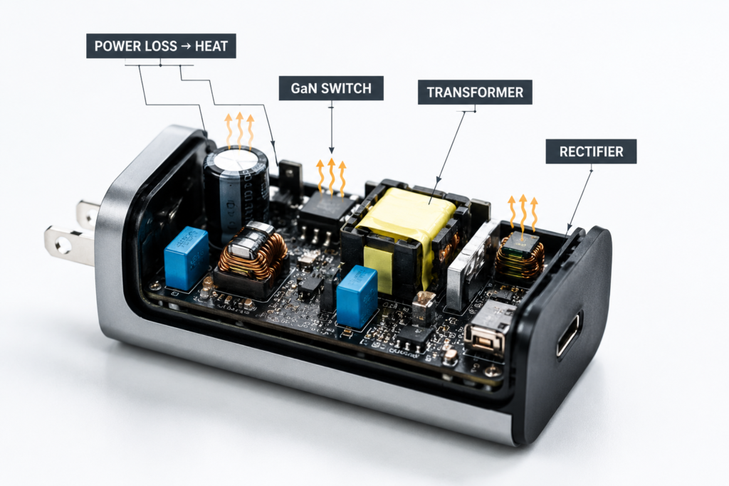
Every charger takes high-voltage alternating current (AC) from the wall and turns it into low-voltage direct current (DC) for your phone or laptop. The full chain looks like this:
AC Input → EMI Filter → Rectification → Power Conversion → Voltage Regulation → USB-C Output
No conversion process is 100% efficient. A small fraction of input power does not reach your device. It turns into heat instead.
You can think of it with two simple formulas:
- Lost power (heat) = Input power – Output power
- Efficiency = Output power ÷ Input power
Modern chargers typically achieve around 85–95% efficiency depending on power level, topology, and design quality. High-power GaN chargers often reach the upper end of this range, while small low-power adapters may operate at lower efficiency. At full load, a 65W charger operating at 90% efficiency loses about 7W as heat.
2.2 The Four Main Heat Sources Inside a Charger
Heat does not come from one place. It comes from four key groups of components, each losing energy in its own way.
(1) Power Switching Devices: MOSFETs and GaN Transistors
These are the high-speed electronic switches inside the charger, turning power on and off thousands or millions of times per second to control voltage.
- Conduction loss: Heat generated as current flows through the device’s internal electrical resistance.
- Switching loss: Energy wasted during the brief moment when the device turns on or off, as voltage and current transition between states.
Higher switching frequency and higher current both increase these losses.
(2) Transformers and Magnetic Inductors
The transformer isolates high-voltage input from low-voltage output and steps the voltage down. It produces two types of loss:
- Copper loss: Heat from electrical resistance in the wire windings.
- Core loss: Heat from magnetic friction inside the core material, split into hysteresis loss and eddy current loss (small circulating currents induced inside the magnetic material).
Higher operating frequencies make core loss more significant.
(3) Rectification Components
On the output side, fluctuating current must be smoothed into steady DC.
- Traditional diode rectifiers: Lose energy through a constant forward voltage drop, which generates noticeable heat at higher currents.
- Synchronous rectification: Uses low-resistance MOSFETs instead of diodes, cutting rectification loss dramatically and reducing heat.
(4) Passive Parts, PCB Traces, and Control ICs
Smaller but still meaningful losses come from:
- Equivalent series resistance (ESR) in capacitors
- Wire resistance in inductors
- Resistance in wide copper traces on the printed circuit board (PCB)
- PD controllers, protocol ICs, and monitoring chips, which consume small amounts of power during operation
2.3 Hot Spots Inside a Charger
Not every part of a charger heats up equally. The highest thermal concentration is usually found in four areas:
- The primary switching stage (where the main power transistors sit)
- The main transformer
- The secondary rectifier stage
- High-current USB-C output paths
Power switches and magnetic components almost always create the strongest hot spots. Good thermal design spreads this concentrated heat out before it reaches the outer case.
2.4 Why Fast Chargers Run Hotter: The Power Density Problem
A 65W old-style laptop brick and a 65W pocket GaN charger may output the same power, but they do not feel the same. The smaller charger has far less internal volume and surface area for its heat. This is power density—measured in watts per cubic centimeter.
For example:
- A large 65W adapter (100 cm³): 65W ÷ 100 cm³ = 0.65 W/cm³
- A mini 65W GaN charger (35 cm³): 65W ÷ 35 cm³ ≈ 1.86 W/cm³
The compact GaN model has nearly 3x the heat density of the larger adapter, even at the exact same output power. As chargers shrink, heat density rises. Cooling a small high-power charger is much harder than cooling a large low-power one. This is the central engineering challenge of modern fast charging.
3. How Heat Leaves a Charger: Three Thermal Transfer Paths
For heat to go from a hot chip to the air in your room, it must travel through multiple steps. There are three fundamental ways heat moves, and all chargers use a mix of all three.
3.1 Thermal Conduction: The Internal Heat Highway
Conduction is heat transfer through solid materials, passed from molecule to molecule without any movement of the material itself. It is the most important path inside a charger.
A typical conduction path looks like this:
Power chip → Solder layer → PCB copper layer → Thermal interface material → Metal shield / case
How well conduction works depends on:
- Thermal conductivity of the material (copper and aluminum are excellent; plastic is poor)
- Contact area between parts
- Interface thermal resistance (gaps and air pockets slow heat down)
Common conductive materials in chargers include copper, aluminum, thermal grease, thermal pads, phase-change materials, and graphite sheets.
3.2 Thermal Convection: The Air-Cooling Path
Convection is heat carried away by moving air. This is how heat finally leaves the charger body and enters the room.
There are two types:
- Natural convection: Warm air rises and cool air replaces it, driven only by temperature difference. This is how nearly all phone chargers work.
- Forced convection: A fan pushes air through the case for much faster cooling. Used only on high-power desktop chargers and laptop adapters.
Convection performance depends on air flow speed, temperature difference, and the total surface area of the case. Case shape and vent placement matter a lot.
3.3 Thermal Radiation: The Minor Contributor
Radiation is heat released as infrared electromagnetic waves. Every warm object radiates heat. In compact consumer chargers, radiation usually plays a smaller supporting role compared with conduction and convection.
It depends on:
- Surface emissivity (how well a surface radiates heat)
- Surface temperature
- Total surface area
Anodized aluminum radiates better than shiny polished metal, but radiation remains a secondary cooling path for most wall chargers.
3.4 The Full Cooling Path in One Picture
Inside a well-designed charger, heat follows a clear journey:
Hot chip → Thermal pad / grease → Heat spreader or copper foil → Inner case structure → Outer case → Room air (convection + radiation)
3.5 Thermal Resistance: The Number That Defines Cooling Ability
Engineers measure cooling performance with thermal resistance, measured in °C/W. It tells you how many degrees the temperature rises for every watt of lost power.
Lower thermal resistance = better cooling.
It is affected by material choice, contact area, interface quality, and overall structure. When a charger runs surprisingly cool for its size, it almost always means the design team lowered total thermal resistance at every step.
4. Charger Thermal Design Architecture: How Engineers Build a Cooler Charger
Effective cooling is not just adding a bigger heat sink. It is a layered system that addresses heat at every stage, from generation to release. A standard charger thermal design follows five core steps:
- Heat generation reduction The first and most important step: make less heat in the first place. This includes choosing efficient semiconductors (GaN), low-loss topologies, and synchronous rectification.
- Heat spreading Concentrated hot spots from chips and transformers are spread across larger surfaces. Graphite films, copper planes, and vapor chambers all serve this purpose.
- Heat transfer Heat moves from internal components to the outer shell through conduction. Thermal interface materials, metal frames, and thermal vias create low-resistance thermal paths.
- Heat dissipation Heat finally leaves the charger into the surrounding air, mostly via natural convection and partially via radiation. For high-power models, forced air cooling accelerates this step.
- Temperature control Sensors and protection circuits monitor temperature and adjust output if needed, ensuring the charger stays within safe limits even under harsh conditions.
This end-to-end architecture is why two chargers with the same wattage can feel very different in real use.
5. Main Charger Cooling Technologies
5.1 Passive Cooling: The Standard for Consumer Wall Chargers
Passive cooling has no moving parts. It relies entirely on conduction, natural convection, and radiation. It is silent, reliable, and low-cost.
Case Material Choices
| Material | Typical Thermal Conductivity (W/m·K) | Strengths | Common Use |
|---|---|---|---|
| Plastic (ABS/PC) | 0.1–0.3 | Low cost, good electrical insulation, easy to mold | 5W–30W basic chargers |
| Aluminum alloy | 150–200 | Excellent heat transfer, also works as EMI shield | 65W+ high-power GaN chargers |
| Magnesium alloy | 50–90 | Lightweight and strong | Premium compact chargers |
Plastic insulates electrically but traps heat. Aluminum moves heat fast but requires careful insulation design inside. Some metal shielding structures serve two purposes: improving heat spreading and reducing electromagnetic interference (EMI).
Internal Thermal Structures
- Thermal interface materials (TIM): Thermal pads, grease, and phase-change sheets fill tiny gaps between hot parts and heat spreaders, replacing air pockets that slow heat transfer.
| Material | Key Advantage |
|---|---|
| Thermal pad | Easy assembly, consistent thickness, reliable for mass production |
| Thermal grease | Lowest interface resistance, ideal for high-heat chips |
| Phase-change material | Stable performance across temperature cycles, reusable thermal contact |
| Graphite sheet | Spreads heat quickly across a flat surface, ideal for eliminating hot spots |
- Graphite films and vapor chambers (VC): Spread hot spots across a wider area so the case can release heat more evenly.
- Thermal potting: Thermally conductive silicone or epoxy fills empty space inside the case. It holds parts in place, insulates, and improves heat transfer.
PCB-Level Cooling
- Large copper planes spread heat across the board.
- Multilayer PCBs carry more current and move more heat.
- Thermal vias: Tiny copper-plated holes carry heat from the top side of the board to the bottom side.
Component Placement Strategy
How parts are arranged inside the case has a huge impact on cooling:
- High-heat components are spaced apart to avoid stacking hot zones.
- Major heat sources are placed close to the outer shell or main heat spreader.
- High-voltage and low-voltage areas are separated for both safety and thermal isolation.
- The transformer is kept away from USB output connectors to prevent heat from reaching the cable and device.
5.2 Active Cooling: For High-Power Use Cases
Active cooling adds moving air to the system. It is much more powerful than passive cooling, but adds cost, noise, and potential points of failure.
- Micro-fan forced air: A small fan pulls air in and pushes it out, dramatically increasing convection.
- Smart fan control: An NTC temperature sensor feeds data to a microcontroller, so the fan runs slow and quiet when cool and speeds up only when needed.
Active cooling is most common on 100W+ multi-port desktop chargers and large laptop power adapters. Liquid cooling exists in industrial and lab settings but is rare in consumer chargers due to size, cost, and reliability tradeoffs.
5.3 Source-Level Cooling: Less Heat Is Better Than More Cooling
The best way to handle heat is to make less of it in the first place. This is where premium chargers gain most of their advantage.
Gallium Nitride (GaN): Reducing Heat at the Source
GaN does not magically remove heat. Its advantage comes from reducing power losses inside the conversion process.
Compared with traditional silicon MOSFETs:
- Lower switching losses
- Lower conduction losses
- Ability to run at much higher operating frequencies
- Smaller magnetic components thanks to higher frequency
The result is higher power density with improved efficiency. In many real-world designs, properly engineered GaN chargers show lower surface temperatures compared with similarly rated silicon chargers.
High-Efficiency Circuit Topologies
- LLC resonant conversion: Reduces switching loss by allowing transistors to turn on when electrical stress is minimized, a technique called zero-voltage switching (ZVS).
- Active clamp flyback (ACF): Recycles energy from leakage inductance (small unwanted magnetic energy stored in transformers) for higher efficiency at high frequencies.
- Synchronous rectification: Replaces lossy diodes with low-resistance MOSFETs on the output side.
5.4 The Engineering Tradeoff: Cooling vs. Everything Else
Cooling performance is never designed in a vacuum. Engineers must balance:
- Cooling ability
- Product size and portability
- Electrical insulation and safety distance
- EMI (electromagnetic interference) shielding
- Production cost
For example, a thick metal inner shell improves cooling and EMI shielding, but adds cost and requires extra insulation layers. Every charger represents a different point on this tradeoff curve.
6. Cooling Design Across Different Charger Types
6.1 5W–20W Low-Power Chargers: Simple Passive Design
Small phone chargers run cool enough that basic plastic cases and simple PCB copper are usually sufficient. No fancy thermal materials are needed, and reliability is very high.
6.2 30W–100W Mid-Power Fast Chargers: Material and Structure Upgrade
This is where thermal design starts to matter. Better models add aluminum inner shells, thermal pads, wider copper planes, and GaN semiconductors to keep surface temperatures acceptable in a compact body.
6.3 Multi-Port Desktop Chargers: Multiple Heat Sources and Dynamic Power Management
Multi-port chargers have more chips and more power stages running at the same time, creating higher total heat and more complex thermal management.
They rely on:
- Distributed heat source layout to avoid concentrated hot zones
- Dynamic power allocation: The charger’s internal controller adjusts power between ports based on device demand and internal temperature. For example, a 100W dual-port charger may run 65W + 30W under normal conditions, but reduce total output if temperatures rise too high.
- In some cases, active fan cooling for sustained multi-device high-power charging
This thermal throttling effect is why a multi-port charger may charge slower when all ports are in use on a hot day—it is protecting itself while still delivering usable power to all devices.
6.4 Laptop Power Adapters: Mature High-Power Architecture
Laptop adapters are larger and built for continuous full-power use. They use proven passive or hybrid cooling designs, with bigger heat spreaders and more internal volume, optimized for long sessions of heavy load.
6.5 GaN vs. Traditional Silicon Chargers
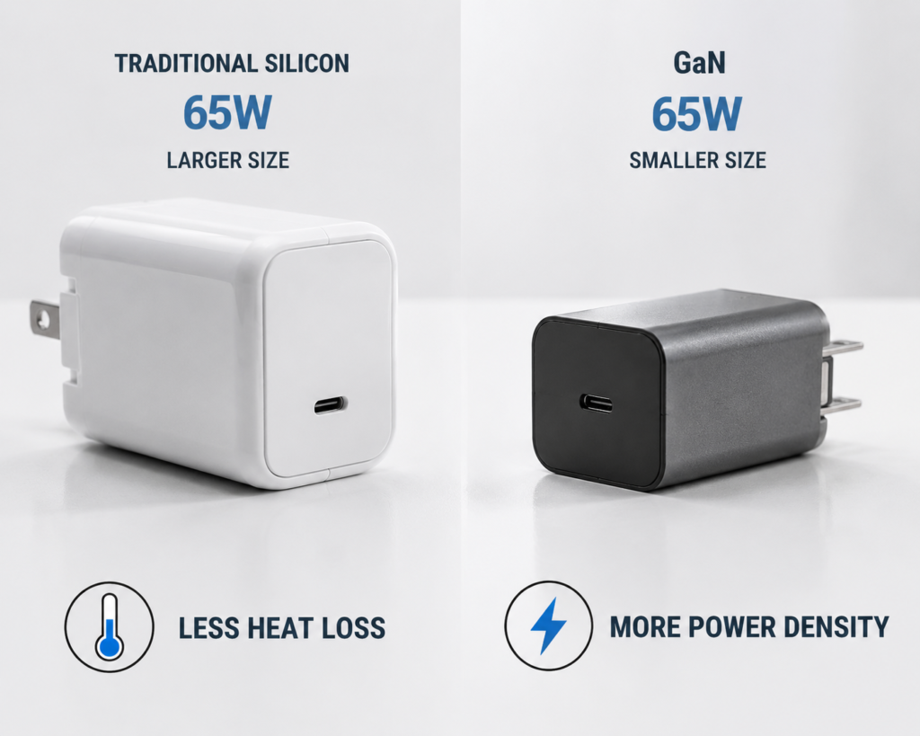
A common myth is that GaN chargers run hotter because they are smaller. In reality:
- At the same power and same size, a well-designed GaN charger runs cooler thanks to lower losses.
- At the same power and smaller size, GaN may feel similar or slightly warmer, but still performs better than silicon squeezed into the same body.
- The biggest win is that GaN delivers high power in sizes where silicon would be impractical.
7. Temperature Protection and Safety Systems
7.1 Temperature Monitoring
Nearly all modern chargers use NTC thermistors—small resistors that change value with temperature—to monitor hot spots. Better designs place multiple sensors near the main switch, transformer, and output ports.
7.2 Thermal Throttling: When Chargers Slow Themselves Down
Before things get dangerous, well-designed chargers reduce output power on purpose. This is called thermal throttling.
The logic is simple:
- Temperature rises past a warning threshold.
- The charger reduces output power.
- Less power means less heat.
- Temperature falls back to a safe level.
This is why a charger may charge slower on a very hot day or when covered. It is not a bug—it is protecting itself and your device.
7.3 Three Levels of Over-Temperature Protection (OTP)
Good chargers use a graded response:
- Level 1 – Power reduction: Lower output power to bring heat down.
- Level 2 – Pause charging: Stop output temporarily and wait for cooling.
- Level 3 – Hard shutdown: Cut power completely in extreme fault conditions.
7.4 Safety and Efficiency Standards
Reputable chargers are tested against global standards. Two of the most important for cooling and efficiency are:
- IEC 62368-1: A widely accepted safety standard for information technology and audio/video equipment. It follows a hazard-based safety approach rather than simply limiting component temperatures, and evaluates risks including accessible surface temperatures, material temperature ratings, and abnormal operating conditions.
- DOE Level VI (US) and EU CoC Tier 2: Strict efficiency rules that indirectly reduce heat by enforcing minimum efficiency levels and low no-load power consumption. DOE Level VI defines minimum efficiency requirements for external power supplies across different power categories.
7.5 How Heat Affects Lifespan
Heat is the single biggest enemy of many electronic components. For many electrolytic capacitors, every 10°C increase in operating temperature can approximately halve expected lifetime. A cooler charger is not just more pleasant to touch—it will also last significantly longer.
8. Practical Guide: Myths, Temperature Checks, and Buying Tips
8.1 Four Common Cooling Myths Debunked
- “If a charger gets warm, it is bad quality.” False. All chargers produce heat. What matters is whether temperature stays within safe design limits.
- “Metal cases always cool better than plastic.” Not automatically. Metal conducts heat faster, but only if the internal heat path is well designed. A plastic charger with good internal layout can outperform a metal charger with bad thermal contact.
- “Fast charger heat damages your phone battery.” No. The charger’s case temperature is not the same as your phone’s battery temperature. Your phone has its own battery management system and thermal protection. A safe charger will not harm a properly working device.
- “A protective case doesn’t affect cooling.” It does. Even a thin plastic skin blocks air flow and traps heat against the surface. For high-power charging, it is better to remove decorative cases.
8.2 Charger Cooling vs. Battery Temperature
One of the most common concerns is that a hot charger will overheat and damage the phone’s battery. In reality, the two are largely separate.
- A charger’s outer case temperature depends on its own internal heat and cooling design.
- A phone’s battery temperature depends on its own charging circuit, battery management system, and internal thermal design.
A properly working certified charger will not force unsafe levels of heat into your device. The USB-C cable and connector also act as a thermal barrier. If the charger overheats, its internal protection will reduce power or shut down before dangerous heat reaches your phone.
8.3 How to Judge Temperature by Feel
| Feeling | Meaning |
|---|---|
| Slightly warm | Normal operation, light to medium load |
| Warm but comfortable to hold | Common during active fast charging |
| Very hot to touch, hard to hold for long | Check ventilation, load, and ambient temperature |
| Burning smell or repeated automatic shutdowns | Stop using and inspect for faults |
8.4 Five Easy Tips for Better Cooling
- Keep the charger on an open, hard surface—not on a bed, couch, or pile of clothes.
- Keep it out of direct sun and away from other heat sources.
- Remove decorative protective sleeves during high-power charging.
- Leave a little space around multi-charger power strips; do not cram them together.
- Occasionally wipe dust from the case and ports to keep air paths clear.
8.5 How to Spot a Well-Cooled Charger by Appearance
- Solid build with a matte or textured surface (better convection and radiation than glossy)
- Visible vent slots on high-power desktop models
- Metal body or metal accents on compact high-power models
- Clear display of recognized safety certifications (UL, CE, FCC, USB-IF)
8.6 Buying Guide: What to Look For
- Prefer GaN-based models for high power in small size.
- Look for efficiency certifications such as DOE Level VI or Energy Star.
- Leave a power margin. If you need 30W, buy a 45W charger—it will run cooler and last longer.
- Always choose models with recognized safety marks.
9. The Future of Charger Cooling
9.1 Better Semiconductors: Less Heat at the Source
GaN is already mainstream, and silicon carbide (SiC) will continue to move into higher-power consumer products. Both reduce switching and conduction loss, making cooling easier from the start.
9.2 Advanced Thermal Materials
Graphene composites, micro heat pipes, and improved vapor chambers will trickle down from industrial and laptop use into premium consumer chargers, moving heat faster with less thickness.
9.3 Smarter Thermal Control
Future chargers will use more predictive algorithms. Instead of only reacting to temperature, they will anticipate load changes and adjust power delivery proactively to keep temperature smooth and steady.
9.4 New Use Cases
As multi-port 200W+ chargers become more common, cooling innovation will follow—including better passive designs and quiet active cooling.
9.5 Wireless Charging Thermal Challenge
Wireless chargers face unique thermal challenges that wired chargers do not. In addition to the usual AC-DC conversion losses, wireless charging adds:
- Coil resistance loss in both the charger and the device
- Eddy current loss in nearby metal components
- Magnetic core loss in the charging coils
- Heat transferred directly to the back of the phone through contact
With Qi2 and MagSafe-style charging growing in popularity, thermal design for wireless pads is an active area of innovation. Solutions include better coil design, ferrite shielding optimization, and in some cases built-in fans or thermoelectric cooling. This is why high-power wireless chargers often run warmer than equivalent wired models.
10. Final Takeaways
Charger cooling is not just “adding more vents.” It is a complete system made of four layers:
- Less heat produced – high-efficiency topologies and GaN semiconductors
- Faster heat transfer – thermal materials, copper planes, and case design
- Better heat release – convection, radiation, and optional fan cooling
- Smarter heat control – sensors, throttling, and multi-level protection
Together, these layers determine how fast a charger really charges, how long it lives, and how safe it is. For consumers, the rule is simple: buy certified, leave room for air, and know that a little warmth is perfectly normal.
FAQ
Q: Why does my USB-C charger get hot while charging?
A: All USB-C chargers produce heat as a side effect of converting wall AC power to device DC power. Switching transistors, transformers, and rectifiers all lose small amounts of energy that turn into heat. Fast chargers run hotter because they move more power in a smaller body.
Q: Does a GaN charger generate less heat than a normal charger?
A: When properly designed, yes. GaN transistors have lower switching and conduction losses than traditional silicon transistors, so less energy is wasted as heat. At the same power level, a good GaN charger is typically more efficient and runs cooler than an equivalent silicon charger.
Q: Can a hot charger damage my phone?
A: A certified, properly working charger will not damage your phone. Your phone has its own internal battery management system and thermal protection that controls charging current and temperature. The charger’s outer case warmth does not directly equal battery heat.
Q: What is a normal surface temperature for a USB-C charger?
A: Warmth during fast charging is normal. If the charger is comfortable to hold, it is operating within typical ranges. If it is too hot to hold for more than a few seconds, or produces unusual smells, check ventilation and stop use if the issue continues.
Q: Why do GaN chargers usually feel cooler?
A: GaN transistors have much lower switching loss and enable smaller, more efficient magnetic parts. Overall efficiency is higher, so less energy turns into heat. At the same power level, a well-designed GaN charger runs cooler than an equivalent silicon model.
Q: Will a protective case on my charger cause overheating?
A: It will raise surface temperature and reduce cooling, especially during high-power use. For short low-power charges the effect is small, but for 65W+ laptop charging it is better to remove the case.
Q: Is it safe to fast charge in a hot summer room?
A: Certified chargers include over-temperature protection and will throttle or shut down if they get too hot. For best speed and lifespan, try to keep chargers in open, cooler areas and avoid enclosed hot spaces like a car dashboard in summer.
Q: Why does my charger get hotter in summer or at night?
A: Cooling depends on the difference between the charger’s temperature and the surrounding air. When room temperature is higher, there is less temperature difference, so heat escapes more slowly. The charger will run warmer even though it produces the exact same amount of heat.
Q: Does a higher watt charger always produce more heat?
A: Not always. Total heat depends on both output power and efficiency. A well-designed 100W GaN charger may run cooler than an older, less efficient 65W silicon charger. What matters most is how much power is lost, not how much power is delivered.
Q: Can I leave my charger plugged in all the time?
A: Certified chargers are designed to be safe when plugged in long-term, and modern efficiency standards keep no-load power very low. However, leaving any power adapter plugged in indefinitely will produce small amounts of standby heat and consume tiny amounts of power. For maximum energy savings and longevity, unplug when not in use for extended periods.
Q: Is it normal for a multi-port charger to run hotter when charging several devices?
A: Yes. Higher total output power means higher total loss and more heat. Good multi-port chargers use dynamic power sharing and thermal throttling to stay within safe limits.
Q: Is a smaller charger always worse at cooling?
A: Not always. A small charger with excellent GaN design and low thermal resistance can outperform a poorly designed larger one. All else being equal, though, more surface area does help cooling. Size is one factor, not the whole story.