
Introduction
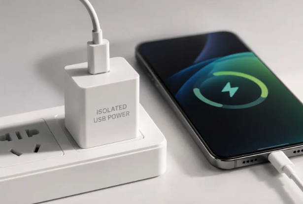
Every time you charge a phone, laptop, or medical device, a hidden safety system inside the power adapter protects you from dangerous mains electricity. This protection is called electrical isolation.
Without proper isolation, dangerous voltage from the input side could transfer to the output side under fault conditions, increasing the risk of electric shock, equipment damage, and system failure.
This guide explains isolated USB power supply design from both user and engineering perspectives, helping beginners understand why isolation matters and how safer USB charging systems are built.
It also explains how isolation technology affects charging safety, performance, and product selection.
For everyday consumer use, most reputable chargers already include basic isolation—but for medical, industrial, or automotive applications, more robust isolation is non-negotiable.
Key Takeaways
✅ Isolated USB power supplies fully separate high-voltage input and low-voltage output via a safety barrier, protecting against electric shock, reducing interference, and preventing equipment damage.
✅ USB-C is only a physical connector shape—it does not guarantee isolation capability. Isolation level depends entirely on internal power architecture and safety design.
✅ Most compliant consumer chargers include basic isolation that meets general safety standards, while medical, industrial, and automotive applications require higher-grade specialized isolation.
✅ Three main isolation technologies are used in isolated USB power designs: transformers for power transfer, optocouplers for feedback signals, and digital isolators for advanced industrial communication and control applications.
✅ Medical-grade isolation is among the strictest safety requirements, with 2×MOPP designs requiring advanced insulation systems, strict leakage current limits, and high-voltage isolation testing under IEC 60601-1. MOPP (Means of Patient Protection) defines the level of protection between the medical device and the patient.
✅ For everyday buyers, checking third-party safety certifications like UL, ETL, or PSE is the simplest way to confirm valid isolation, no teardown required.
✅ GaN semiconductors and USB PD 3.1 EPR high-power standards are driving isolated power supplies toward smaller sizes, higher power output, and lower cost.
1. What Is an Isolated USB Power Supply?
1.1 Core Definition
An isolated USB power supply is a power conversion design with no direct electrical connection between the high-voltage input side (connected to wall power or a vehicle battery) and the low-voltage USB output side.
Think of it like a safety wall built inside the charger: energy passes through the wall via magnetic or optical coupling, but raw high voltage cannot cross to the side you touch.
All isolated power supplies have three core components:
- Primary side: The high-voltage input section connected to mains power
- Isolation barrier: The insulating layer that blocks direct current flow
- Secondary side: The low-voltage output section connected to your USB device
1.2 Isolated vs. Non-Isolated USB Power Supplies: Key Differences
| Comparison Dimension | Non-Isolated USB Power Supply | Isolated USB Power Supply |
|---|---|---|
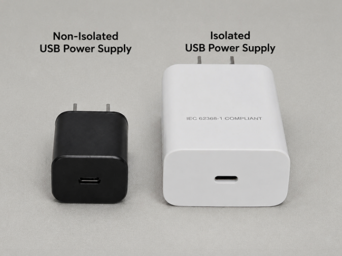
| Internal Connection | Input and output are not separated by a safety isolation barrier and may share a common electrical reference. | Input and output are fully electrically separated, with no direct conductive path |
| Core Advantages | Low cost, small size, high conversion efficiency | High safety, strong interference resistance, suitable for high-risk scenarios |
| Leakage Current | Meets basic safety limits | Tighter controls; medical-grade units limit leakage to microamp levels |
| Safety Rating | Consumer-grade basic safety | Medical/industrial-grade high safety level |
| Typical Applications | Low-cost DC-DC converters, battery-powered electronics, and internal power conversion circuits where electrical separation is not required. | Wall chargers, medical equipment, industrial instruments, automotive USB ports |
| Price Point | Low | Mid to high |
1.3 Three Core Benefits of Isolation Design
Personal Safety Protection
Isolation prevents mains voltage faults from conducting to the USB charging port, significantly reducing electric shock risk. This is especially critical in humid environments, patient care settings, or situations where users may have wet hands.
Equipment Damage Prevention
Isolation helps prevent unwanted ground loop currents between devices powered from different sources. These small unwanted currents can introduce noise, measurement errors, or even damage sensitive electronic interfaces.
Improved Signal Quality
Isolation suppresses common-mode electromagnetic noise, improving signal accuracy for audio equipment, measurement devices, and data transfer interfaces.
1.4 Common Applications & Power Ranges
- Low power (5W–30W): Small home medical devices, IoT sensors, industrial interface modules
- Mid power (30W–100W): Laptop adapters, portable medical diagnostic devices, in-vehicle fast chargers
- High power (100W–240W): High-performance laptops, medical imaging equipment, industrial automation control systems
2. How Isolation Technology Works
2.1 Three Main Isolation Technologies
Magnetic Isolation (Transformer-Based)
Among isolation methods, transformer-based magnetic isolation is the primary technology used for transferring power because it can handle high energy levels efficiently. Energy transfers across the barrier via high-frequency magnetic coupling through a transformer, similar in principle to transformer-based energy transfer used in many electronic power systems. High-frequency operation allows transformers to become much smaller than traditional low-frequency power transformers while maintaining efficient energy transfer.
Optocoupler Isolation
Converts electrical signals to light, passes light across the isolation barrier, then converts light back to electricity on the other side. Low cost and well-established, ideal for low-speed feedback control signals. Note: Optocouplers only transmit signals, not main power.
Digital Isolation (Capacitive/Magnetic Coupling)
Chip-level high-speed isolation technology with no aging degradation and fast transmission speeds. Used for high-speed control signals, industrial communication interfaces, and precision systems where traditional optocouplers may not provide sufficient speed or reliability. In USB power supply designs, digital isolation is mainly found in specialized industrial or medical systems where fast and reliable communication across the isolation barrier is required.
2.2 Key Isolation Parameters Explained
Withstand Voltage Rating
The maximum instantaneous voltage the isolation barrier can safely handle without breaking down, measured in volts. Consumer chargers must meet the insulation and withstand voltage requirements defined by their applicable safety standards. Medical-grade designs usually require much stricter isolation testing, including 4000V AC withstand tests in many 2×MOPP medical applications.
Creepage and Clearance Distance
- Clearance: The shortest straight-line distance through air between two conductive parts
- Creepage: The shortest distance along the surface of insulating material between two conductive parts
Both are designed to prevent high-voltage arcing across the barrier.
Leakage Current
The tiny amount of current that can pass across the isolation barrier via capacitive coupling. Lower values equal higher safety, with strict microamp-level limits enforced for medical patient-contact devices.
Insulation Grade
Ranked from lowest to highest safety: basic insulation → double insulation → reinforced insulation. Higher grades provide greater safety redundancy for fault conditions.
2.3 Components of a Complete Isolation System
- Power isolation module: Handles main energy transfer, typically implemented via an isolation transformer
- Signal isolation module: Handles feedback and control signal isolation when required by the design
- Protection circuits: Over-voltage, over-current, short-circuit, and over-temperature protection to maintain safety even under fault conditions
2.4 Critical Design Factors for Isolation Transformers
The isolation transformer is the heart of any isolated power supply, and its design directly determines safety and performance:
- Turns ratio: Defines the input-to-output voltage conversion ratio
- Leakage inductance: Affects conversion efficiency and electromagnetic interference levels
- Insulation structure: Triple-insulated wire, insulating tape, and barrier walls determine withstand voltage rating
- Parasitic capacitance: Impacts common-mode noise and leakage current levels
3. Common Isolated Power Supply Topologies by Power Level
Different internal circuit designs are used to balance cost, size, efficiency, and safety depending on how much power the charger needs to deliver. For most consumers, the specific circuit design does not affect daily use, but it directly impacts performance and reliability.
- Low-power designs (5–65W): Simple, cost-effective flyback circuits are the most common choice for everyday phone chargers and small electronics. This design is naturally isolated and balances cost and reliability for standard charging needs.
- Mid-power designs (30W–100W): Active clamp flyback designs are used for modern GaN fast chargers, as they reduce energy loss and allow smaller, lighter form factors while maintaining high efficiency.
- Stable continuous-use designs (50W–250W): Forward converter designs are preferred for industrial and medical equipment that runs 24/7, as they deliver stable, low-ripple power for long-term operation.
- Higher-power designs (typically 65W and above): LLC resonant or other advanced isolated topologies are used for high-wattage laptop adapters and professional equipment, offering up to 95% efficiency and lower heat generation for heavy use.
Quick Reference for Common Chargers
| Power Range | Typical Products | Common Internal Design |
|---|---|---|
| 5–30W | Phone chargers, small electronics | Standard flyback |
| 30–100W | GaN fast chargers, thin-and-light laptop adapters | Active clamp flyback |
| 100W+ | High-power laptop adapters and professional equipment | LLC or other advanced isolated topologies |
4. USB-C PD and Isolated Power Supply Design
4.1 How PD Power Levels Impact Isolation Requirements
USB Power Delivery (PD) has dramatically increased the voltage and power levels carried over USB cables, raising the bar for isolation design:
- SPR (Standard Power Range): 5V/9V/15V/20V, max 100W. Conventional isolation designs easily cover this range.
- EPR (Extended Power Range, PD 3.1): 28V/36V/48V, max 240W. Requires improved transformer insulation, larger safety distances, better thermal management, and stronger EMI control because of the higher power density.
- Higher power does not automatically mean higher safety; the isolation design and certification level remain the key factors.
- PPS (Programmable Power Supply): Fine voltage adjustment requires higher bandwidth and precision from the cross-isolation feedback loop.
4.2 Cross-Isolation PD Signal Transmission Methods
For PD communication to work, control signals must cross the isolation barrier between primary and secondary sides:
- Optocoupler solution: Low cost, suitable for low-speed basic PD communication
- Digital isolation solution: May be used in advanced designs where faster signal communication, higher reliability, or stronger noise immunity is required
- Primary-side control solution: No isolation feedback needed, suitable for low-power simple PD applications
4.3 Key Challenges for 240W EPR High-Power Design
- Transformer design: Higher output voltages require upgraded insulation ratings and increased creepage/clearance distances
- EMI suppression: Higher voltage dv/dt increases common-mode noise, requiring optimized shielding and filtering designs
- Thermal management: Higher power density increases heat dissipation demands, requiring careful balance between size and temperature rise
5. How Safety Isolation Is Built Inside a USB Power Supply
5.1 High-Voltage and Low-Voltage Zone Partitioning
Engineers carefully separate high-voltage and low-voltage areas on the internal circuit board to prevent accidental electrical contact and reduce interference. High-voltage components are carefully separated from user-accessible low-voltage areas, with a clear safety gap between sections.
5.2 Safety Distance Requirements
The required width of the safety gap between high and low voltage sections depends on the product’s safety rating. Medical-grade designs require much larger safety distances and stricter insulation requirements than consumer products, to ensure patient protection even under fault conditions.
5.3 Isolation Slots and Safety Keepout Areas
Engineers often add physical isolation slots (cuts in the circuit board) to increase creepage distance and prevent high-voltage arcing across the barrier. These designated keepout areas are kept free of copper traces, conductive holes, and components to preserve the integrity of the safety barrier.
5.4 Safety Components Across the Isolation Barrier
A small number of specialized safety-rated components must cross the isolation barrier to function, including safety-rated Y capacitors for EMI control and optocouplers for transferring feedback signals across the isolation barrier. These parts are carefully selected to meet strict safety standards and precisely positioned to avoid compromising isolation performance.
6. Isolation Requirements by Application Scenario
6.1 Consumer Electronics: Basic Safety Is Sufficient
- Applicable standard: IEC 62368-1 audio/video and information technology equipment safety standard
- Core requirements: Basic or double insulation, meets energy efficiency regulations, balances cost and size
- Typical products: Phone chargers, USB docks, general consumer electronics adapters
6.2 Medical Devices: The Strictest Safety Standards
- Applicable standard: IEC 60601-1 general medical electrical equipment safety specification
- Core requirements: Medical-grade designs require much stricter insulation, leakage current limits, and isolation testing. Some 2×MOPP designs require 4000V AC withstand testing according to IEC 60601-1 requirements. Patient leakage current is strictly controlled at microamp levels, with limits depending on device classification and operating conditions.
- Special constraints: Y capacitor capacitance is limited by leakage current rules, requiring shielded designs to optimize electromagnetic interference without compromising patient safety.
- Typical products: Portable patient monitors, infusion pumps, home medical diagnostic devices
6.3 Industrial Applications: High Reliability for Harsh Environments
- Applicable standards: IEC 62368-1, IEC 61010 measurement and control equipment safety specification
- Core requirements: Wide input voltage range (85–264V AC), wide operating temperature (-40°C to +85°C), surge immunity
- Typical products: Industrial sensors, PLC controllers, automated test equipment
6.4 Automotive Use Cases: Rugged Design for Vehicle Conditions
- Applicable standards: ISO 7637-2 automotive transient immunity test, CISPR 25 automotive EMC standard
- Core requirements: 12V/24V/48V wide automotive voltage input, vibration resistance, load dump protection
- Design note: High-quality automotive power designs may include additional isolation or protection features depending on the application requirements. Unlike medical applications, automotive USB power systems do not always require full galvanic isolation; protection requirements depend on the vehicle architecture and connected equipment.
- Typical products: In-vehicle USB fast chargers, infotainment interfaces, ADAS auxiliary equipment
7. Global Safety Standards and Certification Guide
7.1 General Consumer Safety Standards
- International standard: IEC 62368-1 (replaces older IEC 60950-1 and IEC 60065 standards)
- United States: UL 62368-1, ETL certification
- European Union: EN 62368-1 CE declaration of conformity. CE is required for many products sold in Europe but does not represent independent laboratory certification.
- Japan: PSE safety marking
7.2 Medical-Grade Exclusive Standards
- International standard: IEC 60601-1
- United States: UL 60601-1 + FDA market regulation
- European Union: EN 60601-1 + MDR medical device regulation
7.3 How to Identify Valid Certifications as a Consumer
- Look for UL, ETL, or PSE safety marks on the product casing or specification sheet. These certifications indicate that the product has been evaluated according to specific safety requirements by recognized certification organizations. Certification numbers can usually be verified through official certification databases.
- Medical-grade products will explicitly mark “IEC 60601-1”, “2×MOPP”, or “Hospital Grade” on packaging or specifications.
- Unbranded or uncertified chargers may use lower-quality isolation components or fail to meet required safety standards, creating potential safety risks.
Note: CE marking is a manufacturer’s declaration of conformity, not a third-party certification. It indicates the product meets EU requirements but does not guarantee independent testing.
8. Testing and Reliability Verification for Isolated USB Power
8.1 Safety Testing
Safety testing validates that the isolation barrier works as intended under both normal and fault conditions, with three core tests:
- Hi-Pot (High Potential) Test: Applies controlled high voltage across the isolation barrier for a set period to verify no breakdown or arcing occurs. This is the primary test for insulation strength.
- Insulation Resistance Test: Measures the electrical resistance of the isolation barrier to confirm it meets minimum safety thresholds.
- Leakage Current Test: Measures the tiny amount of current that crosses the barrier during normal operation to ensure it stays within safe limits.
8.2 Real-World Fault Testing
Manufacturers also test abnormal conditions such as short circuits, overheating, component failures, and input power surges to confirm the power supply remains safe even when something goes wrong. These tests simulate real-world accidents to ensure isolation protection remains effective under abnormal operating conditions.
8.3 Performance Testing
Performance testing measures conversion efficiency, output voltage stability, ripple noise, and response speed to load changes, ensuring the charger delivers consistent, reliable power to connected devices.
8.4 EMC Testing
EMC testing verifies that the power supply does not create excessive electromagnetic interference and can operate reliably in noisy environments, which is especially important for industrial and automotive use cases.
8.5 Long-Term Reliability Testing
Long-term testing includes temperature cycling, high-humidity exposure, and extended aging tests to confirm the power supply maintains safety and performance over years of use.
9. Practical Buying Guide: How to Choose and Avoid Pitfalls
9.1 Three-Step Selection Method
- Match your use case: Consumer-grade is fine for everyday charging; medical/industrial/automotive equipment requires application-specific rated products.
- Verify certifications: Prioritize reputable brand products with UL, ETL, or PSE recognized safety certifications.
- Match power rating: Choose a product matching your device’s rated power; there is no benefit to buying unnecessarily high-wattage units.
9.2 How to Verify Isolation Performance
- For general consumers, authoritative certification marks are the most reliable indicator—no teardown or home measurement is required.
- For professional users, isolation validity can be confirmed via professional withstand voltage and insulation resistance testing.
Is USB-C Automatically Isolated?
No. USB-C only defines the connector and communication standard. Isolation depends on the internal power supply design, safety components, and certification level.
9.3 What Consumers Should Not Judge by Appearance
You cannot confirm isolation quality by looking at the charger size or printed wattage number. Real safety depends entirely on internal component design, insulation structure, and official safety certification.
A USB-C connector only tells you the physical connection standard, not the internal safety level. A small, sleek charger from a reputable brand may have better isolation than a bulky no-name unit.
9.4 Common Misconceptions to Avoid
| Common Misconception | Correct Fact |
|---|---|
| USB-C ports mean isolated power | USB-C is only a physical connector shape. Isolation capability depends entirely on internal power architecture and safety design. |
| Higher wattage = safer | Safety level is unrelated to power. It is determined by insulation design, safety standards, and certification grade. |
| Higher isolation grade is always better | Basic isolation is sufficient for normal consumer use. Over-specifying isolation adds unnecessary cost and size. |
| Any charger with a transformer has valid isolation | Transformer insulation grade, PCB safety distances, and creepage all affect final isolation effectiveness. |
| Isolated power supplies are always very inefficient | Modern GaN + active clamp designs can reach 93%+ efficiency, with very little gap compared to non-isolated solutions. |
9.5 Tips for Buying Medical-Grade Chargers
- For medical devices requiring patient protection, choose chargers explicitly rated according to IEC 60601-1 with the appropriate MOPP level specified by the device manufacturer.
- Prioritize reputable medical brands with FDA (US) or MDR (EU) clearance.
- Never use standard consumer-grade chargers to power medical devices that make direct patient contact.
10. Frequently Asked Questions (FAQ)
Q: Do I need an isolated power supply for regular phone charging?
A: For everyday consumer use, any reputable brand charger with valid third-party safety certification includes sufficient basic isolation to meet safety standards. You do not need to pay extra for medical-grade isolation for normal phone charging.
Q: Is every USB-C charger automatically electrically isolated?
A: No. USB-C describes the connector and charging protocol, not the internal safety architecture. A safe USB-C charger requires proper isolation design and compliance with relevant safety standards.
Q: Is a bigger charger safer than a smaller charger?
A: No. Charger size does not determine safety. Safety depends on internal isolation design, third-party safety certification, and component quality, not physical size. Modern GaN chargers can be smaller than older designs while meeting the same or higher safety standards.
Q: Are cheap USB chargers dangerous?
A: Uncertified cheap chargers often cut corners on isolation barriers, use substandard insulation materials, and skip required safety testing. The risk is not high wattage—it is missing or low-quality isolation that could fail to maintain safe separation between the input and output sides under abnormal conditions, creating electric shock or fire risk. Always choose reputable brands with valid safety certifications.
Q: Why do medical devices require isolated USB power?
A: Medical devices often make direct skin contact with patients, some even connect to the heart. Isolation prevents dangerous mains leakage current from passing through the patient’s body, which could cause injury or interfere with sensitive medical equipment readings.
Q: Does USB-C PD fast charging require special isolation design?
A: Standard 100W PD (SPR range) works with conventional isolation designs. 240W PD 3.1 EPR high-power designs require upgraded transformer insulation and increased safety distances to handle the higher 48V output voltage.
Q: How can I quickly check if a charger has safe isolation?
A: Look for recognized safety certification marks like UL, ETL, or PSE on the product casing or official specification sheet. Reputable brand products with valid certifications will always include proper basic isolation.
Q: Why are isolated USB power supplies more expensive than regular ones?
A: Isolation requires additional components (isolation transformers, optocouplers, safety-rated capacitors), larger PCB size for required safety distances, and stricter certification testing. All of these add manufacturing and compliance cost.
Q: Are in-vehicle USB chargers required to use isolated designs?
A: Not all basic car chargers are isolated. High-quality automotive power designs may include additional isolation or protection features depending on the application requirements. Isolated designs may be recommended when powering sensitive electronics or when additional electrical separation is required.
Q: Does a USB-C cable provide electrical isolation?
A: No. USB-C cables only carry power and data between the charger and device; they do not include any safety isolation. All safety isolation is built into the power adapter itself. A high-quality cable cannot fix a faulty or unisolated charger.
Q: What kind of charger is safe for charging home medical devices?
A: Always use a charger explicitly certified to medical IEC 60601-1 standards with the appropriate MOPP level specified by the device manufacturer, purchased from a reputable medical device brand. Never substitute a standard consumer phone charger.
11. Future Trends
Higher Power Density
Widespread adoption of GaN semiconductors paired with high-efficiency circuit designs enables smaller sizes and higher power output. Planar transformer technology is also driving thinner, more modular isolated power designs.
Increased Integration
Single-chip solutions integrating power isolation, signal isolation, and USB protocol layers are drastically reducing design complexity. Integrated isolation modules are becoming more common, shortening development cycles for low-to-mid power products.
Smarter Functionality
Digital power control enables adaptive adjustment, fault monitoring, and health management. Intelligent dynamic power allocation is also becoming standard in multi-port isolated chargers.
Evolving Standards
USB PD 3.1 EPR 240W high-power adoption is driving upgrades to isolation withstand and thermal design. The EU common charger directive is also pushing standardized isolation solutions, while medical and industrial safety standards continue to tighten requirements.
12. Final Thoughts
Isolated USB power supplies are not just a premium upgrade to regular chargers—they are purpose-built safety architectures designed to protect people and equipment by eliminating direct electrical connection between high-voltage input and low-voltage output.
For everyday consumer use, reputable brand products with valid third-party safety certifications provide more than enough protection for normal charging needs. For medical, industrial, or automotive applications, however, matching the correct isolation grade and application-specific certification is non-negotiable for safety and reliability.
As USB-C charging continues to expand into laptops, vehicles, medical devices, and industrial systems, isolated power supply technology will remain a critical foundation for safer and more reliable charging.
Understanding isolation helps consumers choose safer USB-C chargers and helps engineers design reliable power systems for modern electronic devices.