
1. Introduction: Why Connectors Rely on Injection Molding
Every day we use charging cables, USB drives, and display cables, all fitted with various connectors. These seemingly simple devices house precision metal conductive parts inside, protected by an outer plastic housing—almost always produced through injection molding, an indispensable process in connector manufacturing.
Core Functions of the Plastic Housing
The plastic shell of a connector is far more than just a cosmetic cover. It serves several critical purposes: it provides electrical insulation to prevent short circuits and electric shock; it holds tiny conductive pins in exact positions so they do not shift or loosen; it offers mechanical protection against repeated plugging, bending, and impact; and it enables sealing for water and dust resistance.
How Injection Molding Determines Quality and Service Life
The durability of a connector is largely defined by its injection molding quality. Poor bonding between plastic and terminals leads to loose pins and intermittent connections after just a few uses. Internal bubbles or cracks make connectors vulnerable to moisture and breakage. Inaccurate dimensions result in plugs that are too tight or too loose. In short, injection molding directly determines how long a connector will last and how reliably it will perform.
Common Injection-Molded Connectors in Daily Life
Injection molding is used for nearly all familiar connector types: USB and Type-C ports for phones and laptops, HDMI connectors for TVs and monitors, RJ45 Ethernet ports for routers and network cables, DC power jacks for laptops and adapters, audio jacks, and industrial connectors. All depend on injection molding to bond the housing and internal components together.
2. Understanding Connector Injection Molding
Basic Definition
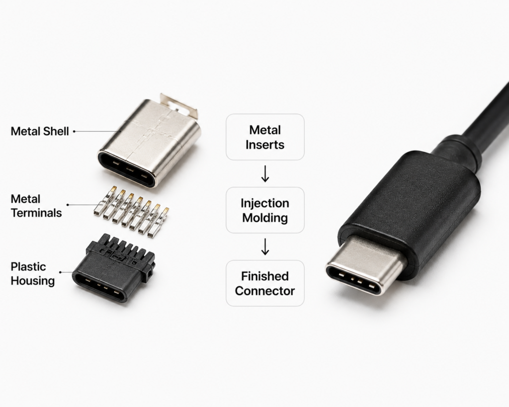
Put simply, connector injection molding melts plastic pellets into a liquid state, injects the molten material under high pressure into a custom mold, and allows it to cool and solidify. The result is a plastic connector body that perfectly matches the mold shape, while firmly encapsulating the internal metal terminals. This is essentially a form of insert molding—embedding metal parts inside plastic during the forming process.
How It Differs From Standard Plastic Part Molding
Unlike standard injection molding that produces solid plastic parts, connector molding has unique requirements. First, metal terminals must be pre-positioned inside the mold with extreme precision. Second, connectors are small with very tight pin spacing, requiring far higher dimensional accuracy than ordinary plastic housings. Third, they must meet electrical and environmental performance standards, such as insulation and temperature resistance, in addition to mechanical strength.
Where Molding Fits in the Full Connector Manufacturing Flow
A complete connector production line typically starts with stamping metal conductive terminals, followed by plating to improve conductivity and corrosion resistance. Injection molding is the next core step: terminals are placed into the mold and encapsulated in plastic. After molding, the parts go through final assembly, testing, and packaging. Molding is the critical stage that turns separate components into a complete connector body.
Overview of the Full Molding Process
The connector injection molding process can be summarized as: prepare raw materials and tooling → load metal terminals into the mold with precise alignment → close the mold and inject molten plastic → hold pressure and cool to set the plastic → open the mold and eject the parts → remove excess flash and gates → inspect and package finished products.
3. Common Materials for Connector Injection Molding
A connector’s performance starts with material selection. Different combinations of plastic and metal suit different application scenarios.
Main Plastic Resins and Their Properties
A variety of engineering plastics are used in connectors, each offering distinct advantages such as heat resistance, toughness, or high precision.
Role and Common Materials of Metal Inserts
Metal inserts in connectors are mainly conductive terminals and shielding shells. They transmit electrical signals or power and add structural rigidity. Common materials include brass, phosphor bronze, and stainless steel. Phosphor bronze offers good elasticity for mating terminals; brass provides balanced conductivity and cost; stainless steel is used for high-strength, corrosion-resistant industrial connectors.
Application Comparison of Different Materials
The table below summarizes the most common plastic materials, their key characteristics, and typical uses:
| Plastic Material | Key Characteristics | Typical Connector Applications |
|---|---|---|
| PA (Nylon) | Good toughness, wear resistance, moderate cost | DC power connectors, standard USB ports |
| PBT | Excellent dimensional stability, good insulation, heat resistance | RJ45 Ethernet ports, HDMI connectors |
| LCP (Liquid Crystal Polymer) | High heat resistance, extreme precision, excellent flow | Compact Type-C connectors, high-speed interfaces |
| TPE / TPU | Good elasticity, soft feel, excellent flex resistance | Cable connector overmolds, waterproof connectors |
4. Key Design Elements of Connector Injection Molds
The mold is the “template” of injection molding. Its design directly determines whether parts can be produced and how accurate they will be.
Basic Mold Structure
A connector mold consists mainly of a fixed half and a moving half, with internal cavities that form the product shape, plus runner systems, cooling channels, and ejection mechanisms. Precision connector molds are usually multi-cavity designs, producing several parts per cycle for higher efficiency.
Insert Positioning and Anti-Shift Design
This is the most critical part of connector mold design. Tiny metal terminals must stay perfectly stationary during injection, otherwise the high-pressure plastic flow will push them out of alignment, ruining the part. Molds use dedicated alignment pins and slots to secure both ends of each terminal, ensuring zero positional shift during molding.
Gate and Runner Design
The gate is the “entry point” where plastic enters the cavity, and the runner is the “channel” that delivers the material. Connector molds typically use very small gates placed at carefully chosen locations—they must allow fast, complete filling without leaving visible marks on the part, and must avoid directing plastic flow directly against the delicate terminals.
Cooling and Venting Design
The cooling system ensures fast, uniform solidification of the plastic. Uneven cooling causes warping and dimensional errors. Venting channels remove trapped air from the cavity, preventing short shots and internal bubbles.
Why Precision Molds Matter for Connector Quality
Connectors are often only a few millimeters in size, with pin spacing of less than one millimeter. Mold accuracy must be controlled to the micrometer level. Higher mold precision means more consistent dimensions, more accurate terminal positioning, and better mating feel and durability. High-precision tooling is the foundation of premium connector production.
5. Full Production Process of Connector Injection Molding
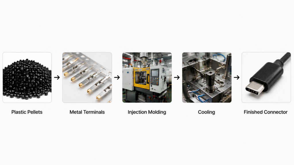
Pre-Production: Material Drying and Mold Setup
Before mass production, plastic pellets are dried to remove moisture—otherwise bubbles and silver streaks will appear in the finished parts. The mold is mounted on the injection machine, and parameters such as temperature, pressure, and alignment are calibrated. Trial shots are produced and inspected before full production begins.
Insert Preparation and Loading
Metal terminals are inspected for deformation and contamination before loading. In some cases they are preheated to reduce the temperature difference with molten plastic and improve bonding. For mass production, robotic arms place terminals into the mold cavities with high precision.
Injection, Packing, and Cooling
Once the mold closes, the injection machine pushes molten plastic into the cavities under high pressure until they are completely filled. After filling, pressure is maintained to pack more material into the cavity, compensating for plastic shrinkage as it cools and preventing sink marks. The mold’s cooling system then runs until the plastic fully solidifies.
Demolding and Post-Processing
When the plastic is fully cooled, the mold opens and ejector pins push the finished connectors out. Excess gate material and fine flash (burrs) are then removed to leave a smooth, clean surface.
Final Inspection and Packaging
Every production batch undergoes visual and dimensional sampling checks. Once parts are confirmed free of defects and within specification, they are packaged in anti-static bags and sent to the finished goods warehouse.
6. Core Process Parameters That Affect Quality
Injection molding is a precise process. Small adjustments to temperature, pressure, and timing all affect final product quality.
Temperature: Barrel Temperature and Mold Temperature
Barrel temperature determines whether plastic melts properly. Too low and the plastic will not fill the cavity completely; too high and the material can degrade and burn. Mold temperature affects cooling speed and surface finish. A moderately higher mold temperature produces smoother surfaces and stronger bonding, but lengthens cycle time.
Pressure: Injection Pressure and Packing Pressure
Injection pressure drives plastic into the mold. Insufficient pressure causes short shots; excessive pressure causes flash and can damage the mold. Packing pressure is maintained during the cooling phase to compensate for shrinkage. Insufficient packing leads to sink marks and internal porosity.
Time: Injection, Packing, and Cooling Duration
Injection time must be long enough to fill the cavity. Packing time must continue until the gate solidifies to prevent plastic from flowing back out. Cooling is the longest stage—parts must be fully set before demolding, otherwise they will deform. Too little time reduces quality; too much reduces efficiency.
Controlling Molding Shrinkage
Plastic shrinks as it cools from molten to room temperature, a property known as molding shrinkage. Different materials shrink at different rates. Mold designers account for shrinkage in advance, and process technicians adjust packing pressure and mold temperature to keep shrinkage within acceptable limits for accurate final dimensions.
7. Overmolding Process
Many connectors, especially cable-mounted plugs, have a soft outer plastic layer produced through overmolding.
What Is Overmolding?
Overmolding, also called two-shot molding, is a two-step process: first a rigid inner body is molded, then it is placed into a second mold and a soft outer layer is molded over it. The result combines the structural strength of hard plastic with the feel and protection of soft plastic.
Single-Shot vs. Two-Shot Overmolding
Single-shot molding is the standard single-step process, producing parts from one material. It is simple and low-cost. Two-shot overmolding bonds two materials together: rigid plastic for strength and dimensional accuracy, and soft plastic for grip, flex relief, and waterproof sealing. It is a more complex, higher-cost process.
Purpose and Applications of Connector Overmolding
Overmolding offers clear benefits. It improves flex resistance—for example, the soft strain relief on a charging cable absorbs bending stress and prevents the cable from breaking at the plug. It also improves waterproof sealing by creating a tighter bond between the housing and cable, and adds a non-slip, durable surface. It is widely used on cable connectors, waterproof connectors, and industrial plugs.
8. How Injection Molding Shapes Connector Performance
Mechanical Strength and Flex Resistance
Well-filled, well-bonded injection molding gives a connector high mechanical strength and resistance to drops and impacts. Overmolding greatly improves flex life and reduces cable breakage at the connector body. Poor molding with internal bubbles or weak weld lines leads to easy cracking under stress.
Terminal Retention Stability
One of the core purposes of molding is to secure metal terminals. With accurate insert positioning and strong plastic-to-metal bonding, terminals stay precisely aligned for thousands of mating cycles without loosening or shifting. With poor retention, terminals can push back or bend during use, causing intermittent connections or failure.
Waterproof Sealing and Electrical Insulation
High-precision molding creates a seamless bond between plastic, metal, and cable, enabling effective water and dust sealing. Many waterproof Type-C connectors rely on precision molding for their sealing performance. Proper material selection and full molding also ensure consistent electrical insulation, preventing short circuits and leakage.
Temperature and Environmental Resistance
Different plastic materials offer different temperature ratings, and molding quality also affects performance under extreme conditions. If internal stress is not relieved, connectors may crack during temperature cycling. With the right material-process match, connectors can operate reliably in high heat, cold, and humid environments.
9. Common Injection Molding Defects and Causes
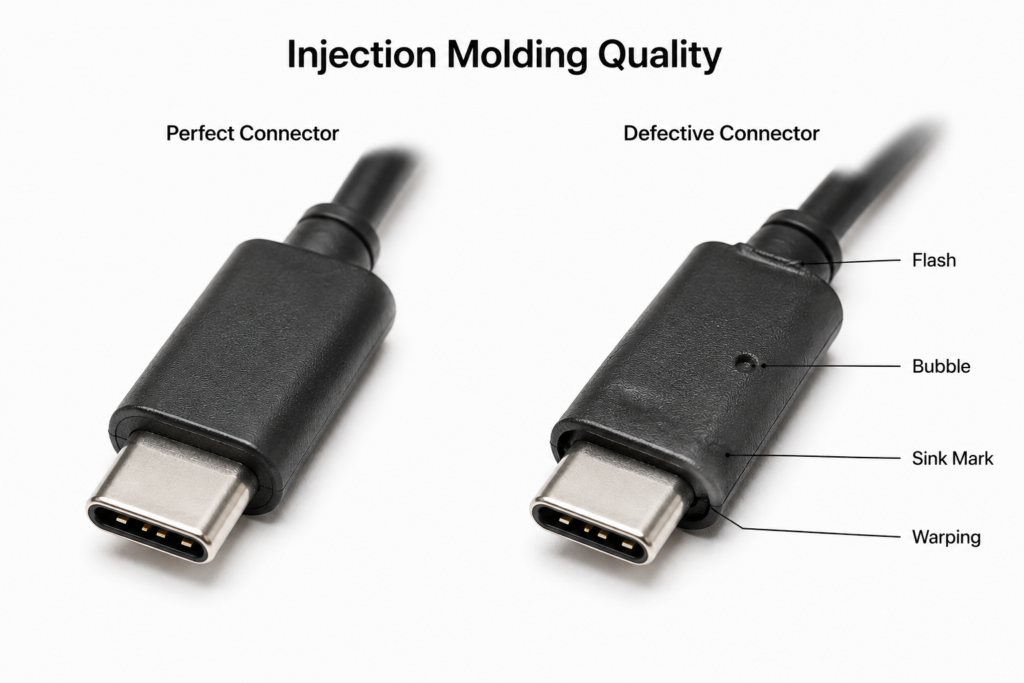
Even small deviations in parameters or mold condition can cause defects in connector molding. The table below lists the most common issues and their visible signs:
| Defect Name | Visible Appearance | Primary Causes |
|---|---|---|
| Flash | Thin excess plastic along part edges | Poor mold clamping, excessive injection pressure |
| Sink Mark | Small dents or depressions on the surface | Insufficient packing, plastic shrinkage, uneven cooling |
| Bubbles | Air pockets inside or on the surface | Undried material, poor venting, fast injection speed |
| Short Shot | Incomplete filling, missing sections of the part | Low injection pressure, low temperature, poor venting |
| Warping | Part is bent or not flat | Uneven cooling, high internal stress, uneven shrinkage |
| Insert Shift | Metal terminals are misaligned | Poor positioning, excessive plastic flow force |
Weld Lines and Cosmetic Defects
Beyond the defects listed above, weld lines, burn marks, and silver streaks are also common. Weld lines form where two flow fronts meet; they are not only cosmetic but also reduce structural strength. Burn marks are dark discoloration caused by overheated plastic decomposing. Silver streaks are silvery lines caused by moisture in the raw material.
10. Quality Inspection of Finished Connectors
After molding, connectors must pass strict inspection before they are approved for release.
Visual and Dimensional Inspection
First comes visual inspection to check for flash, sink marks, bubbles, discoloration, and other obvious defects. Dimensional inspection uses precision measuring tools to verify critical dimensions and terminal positions, ensuring proper fit and mating feel.
Mechanical Testing: Pull Force and Mating Durability
Two key mechanical tests are performed. Pull force testing measures how strongly terminals are bonded to the plastic, ensuring they will not pull out under stress. Mating cycle testing repeatedly plugs and unplugs the connector thousands of times to verify it does not loosen or lose contact.
Environmental Reliability: Temperature Cycling and Salt Spray
Environmental testing simulates harsh operating conditions. Temperature cycling alternates between high and low temperatures to check for cracking or failure. Salt spray testing evaluates corrosion resistance, especially for industrial and outdoor connectors.
Electrical Performance Verification
Finally, electrical testing measures insulation resistance, dielectric strength, and continuity to ensure safe operation and reliable signal and power transmission.
11. Molding Characteristics of Common Connector Types
Different connector types have different molding requirements based on their structure and intended use.
USB and Type-C Connectors
Type-C connectors are compact with many pins, requiring extremely high terminal positioning accuracy and tight dimensional tolerances. They typically use high-flow, heat-resistant materials like LCP, with high-precision multi-cavity molds. Standard USB-A connectors are slightly larger, use more mature processes, and commonly use PBT or PA materials.
HDMI and RJ45 Connectors
HDMI connectors carry high-speed signals, so they require plastics with good dielectric properties, usually PBT or LCP. Precise shielding shell positioning and sealing are important. RJ45 Ethernet ports have more complex internal structures with plastic separators, requiring more sophisticated mold design. They typically use PA or PBT for balanced strength and cost.
DC Power and Audio Connectors
DC power and audio connectors have simpler structures and slightly lower precision requirements than data connectors. They commonly use PA or PBT materials, with a focus on secure terminal retention and insulation performance, optimized for cost.
Industrial and Automotive Connectors
Industrial and automotive connectors have the highest reliability requirements. They must withstand high temperatures, vibration, water, and dust. They use high-performance engineering plastics, often with overmolded sealing, and are built to much stricter tooling and process standards than consumer-grade connectors.
12. Industry Trends and Future Outlook
Miniaturization and High-Precision Molding
As electronics get thinner and lighter, connectors are shrinking and gaining more pins in tighter spaces. Future molding processes will continue toward higher precision and miniaturization, with advancing mold accuracy and process control to support ever-smaller, more precise connectors.
Automated and Smart Manufacturing
Modern connector molding already widely uses robotic loading and unloading. The future will bring even greater intelligence. Sensors will monitor temperature and pressure data for every cycle in real time, and algorithms will auto-adjust parameters, reducing manual intervention and improving yield and consistency.
Eco-Friendly Materials and Green Manufacturing
Sustainability is a major industry trend. More recyclable, low-pollution eco-friendly plastics will be adopted for connector molding. Production processes will also become more energy efficient, reducing waste and energy consumption for low-carbon, sustainable manufacturing.
13. Summary
Injection molding is an irreplaceable core process in connector manufacturing. It bonds tiny metal terminals and plastic housings into complete, durable functional components. Every step—from material selection and mold design to process parameter tuning—influences the final quality and service life.
Behind every small connector in our daily electronics lies multiple layers of technology: materials, tooling, and process engineering. Quality injection molding not only delivers smooth plugging feel, but also ensures stable performance and long service life through years of daily use. As technology advances, connector molding will become more precise, smarter, and more sustainable, continuing to deliver reliable connectivity for all kinds of electronic devices.