
Many people specifically choose shielded cables when shopping, assuming the “shielded” label guarantees complete immunity to electromagnetic interference. But in practice, they often run into issues: audio hum, unstable network connections, or occasional glitches in industrial equipment. After troubleshooting, the root cause is rarely the shield itself—it’s improper grounding.
Think of the shield as a wall that blocks interference, and grounding as a drainage channel built into that wall. Without a drainage channel, the interference trapped by the wall has nowhere to go, and eventually disrupts the signals inside. This article explains the principles, methods, and common misconceptions of shield grounding in plain language, so you can get the full protective benefit from your shielded cables.
1. What Is Shield Grounding and Why Does It Matter?
1.1 What Is a Shield?
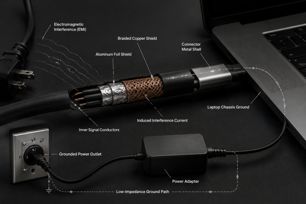
Inside a cable are conductors that carry signals or power. The shield is a metallic layer wrapped around these inner conductors. Its core function is to block external Electromagnetic Interference (EMI) and Radio Frequency Interference (RFI), protecting internal signals while also preventing internal signals from radiating outward and disturbing other devices.
Three common shield materials are widely used:
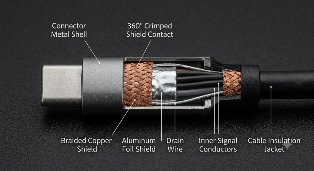
- Aluminum foil: Lightweight and low-cost, excellent at blocking high-frequency interference, often used with a drain wire
- Braided copper: Flexible and resistant to bending, performs better against low-frequency interference
- Composite shield: A dual-layer structure of foil plus braided copper, offering the highest protection for demanding applications
A common misconception is that “any shield automatically stops interference.” The shield is only the foundation of protection. How well it works depends heavily on whether it is properly grounded.
1.2 What Is Shield Grounding?
Shield grounding means creating a reliable electrical connection between the cable shield and the equipment’s grounding system, providing a low-impedance path for interference currents induced on the shield.
One key point to correct: the shield does not “absorb” interference—it redirects it. External electromagnetic fields induce currents on the shield. Without grounding, these currents remain trapped on the shield and can couple into the inner conductors. With proper grounding, the interference currents flow directly away through the ground path, leaving the desired signal undisturbed.
1.3 Why Shield Grounding Is Often Misunderstood
In daily life, most people associate grounding only with “shock prevention” and know little about its role in shielding. Common misunderstandings include:
- Assuming a shield alone guarantees interference protection, ignoring the role of grounding
- Believing all grounding serves only electrical safety, without distinguishing between safety ground and shield ground
- Thinking a floating shield works just as well as a grounded one
In reality, poor or missing grounding drastically reduces the shield’s effectiveness. The difference is especially noticeable in high-frequency and high-interference environments.
2. Why Must a Shield Be Grounded?
2.1 How Electromagnetic Interference Enters Cables
We are surrounded by invisible electromagnetic fields from phones, Wi‑Fi routers, motors, and power lines. Interference reaches cable interiors through four main paths:
- Electric field coupling (capacitive coupling): Similar to static attraction, a charged interference source induces charges on conductor surfaces through electric fields
- Magnetic field coupling (inductive coupling): Similar to how a transformer works, current-carrying wires create magnetic fields that induce interference currents in adjacent cables
- High-frequency radiative coupling: At very high frequencies, electromagnetic waves radiate directly onto cables like light
- Common-mode noise conduction: Interference travels through shared ground or power lines and affects the entire system
2.2 How a Shield Reduces Interference
A metallic shield acts like a protective metal jacket around inner conductors. Thanks to the conductivity of metal, it blocks most interference energy at its surface:
- Most incoming electromagnetic fields are reflected off the metal shield
- A small amount of energy that penetrates induces currents on the shield surface
- These induced currents flow only along the shield surface and barely reach the inner conductors
In short, the shield keeps interference “outside the door.” But that trapped energy needs an exit—and grounding provides it.
2.3 What Happens Without Grounding?
If the shield is left completely ungrounded (floating), it becomes a floating conductor:
- Induced charges cannot escape and build up on the shield
- Accumulated charges couple back into the inner signal conductors through capacitive effects
- The shield, intended to reduce interference, instead becomes a relay for interference
This effect is especially severe at high frequencies: the higher the frequency, the stronger the coupling. A floating shield offers almost no real protection, and may even perform worse than no shield at all.
3. How Shield Grounding Actually Works
3.1 How Interference Currents Form
To understand grounding, first understand how interference currents originate:
- External electromagnetic fields travel through space and reach the cable shield
- Electromagnetic induction creates induced currents on the metal surface of the shield
- These interference currents flow along the length of the shield
Without a ground path, the currents oscillate and couple on the shield, eventually disturbing the internal signal.
3.2 How Grounding Diverts Interference
When the shield is properly grounded, it opens a fast track for interference currents:
- Induced interference currents on the shield flow preferentially to the lowest-impedance ground point
- The currents discharge directly through the grounding system instead of flowing the full length of the shield
- Electromagnetic induction on the inner conductors is greatly reduced, improving signal quality
A simple analogy: the shield is a roof catching rainwater, and grounding is the downspout. Without a downspout, water spills over the edges everywhere. With a downspout, water drains away cleanly and never reaches the interior.
3.3 High-Frequency vs. Low-Frequency Grounding Requirements
Grounding is not just “connect and forget.” High-frequency and low-frequency scenarios have very different requirements:
- Low-frequency scenarios: Ground resistance matters most. The overall resistance of the entire ground path determines how well low-frequency interference is drained
- High-frequency scenarios: Ground impedance matters most. Due to the skin effect, high-frequency currents travel on conductor surfaces, and impedance rises sharply with path length. Wire length, contact area, and connection method matter far more than overall resistance
In short: low frequency cares about low total resistance; high frequency cares about short paths and large contact areas. This is why different applications call for different grounding methods.
4. Common Shield Grounding Methods
In practice, three main shield grounding methods are used, each suited to different scenarios. None is universally superior—what matters is suitability. The table below compares their core characteristics.
| Grounding Method | Core Connection | Main Advantage | Main Disadvantage | Typical Applications |
|---|---|---|---|---|
| Single-Ended Grounding | Shield grounded at one end only, other end floating | No ground loop, avoids low-frequency circulating currents | Moderate high-frequency performance | Low-frequency analog signals, audio cables, short measurement lines |
| Both-Ends Grounding | Shield grounded at both ends to equipment ground | Excellent high-frequency shielding, strong discharge capability | Risk of ground loop if end potentials differ | High-frequency digital signals, Ethernet, video cables, long industrial buses |
| Multi-Point Grounding | Shield grounded at regular intervals along its length | Lowest high-frequency impedance, best protection | Complex installation and maintenance | UHF communication systems, data centers, large industrial plants |
4.1 Single-Ended Grounding
In single-ended grounding, only one end of the shield is connected to the grounding system; the other end is left completely floating and unconnected to any metal enclosure or ground.
- Principle: With only one ground point, no closed loop is formed, so no ground-loop current can exist
- Advantages: Simple to implement, completely eliminates low-frequency ground-loop interference
- Limitations: Higher shield impedance at high frequencies, reduced effectiveness on long cables
- Common uses: Home audio cables, analog sensor lines, short measurement instrument cables
4.2 Both-Ends Grounding
In both-ends grounding, the shield is connected to the chassis or ground system of the equipment at both ends of the cable.
- Principle: Drain paths exist at both ends, allowing high-frequency interference to discharge locally for lower overall impedance
- Advantages: Far better high-frequency shielding than single-ended grounding; the dominant approach for high-speed digital transmission
- Potential issue: If the two ground points are at different potentials, a ground-loop current forms in the shield, introducing new interference
- Common uses: Ethernet cables, HDMI/DisplayPort cables, USB cables, industrial Ethernet buses
4.3 Multi-Point Grounding
In multi-point grounding, additional ground connections are made at regular intervals along the cable length.
- Use case: Primarily for very high frequency, long-distance large systems; rarely used in consumer applications
- Advantages: Lowest high-frequency ground impedance; interference can discharge immediately along the path for best protection
- Limitations: Demands very strict equipotential bonding of the grounding system; difficult and costly to install and maintain
- Common fields: Cell towers, broadcast transmitters, large data centers, plant-wide automation backbones
5. What Is a Ground Loop?
Ground loops are the most talked-about downside of both-ends grounding. They cause many common interference issues, from audio hum to video noise.
5.1 How Ground Loops Form
Two conditions create a ground loop:
- The shield is grounded at both ends, forming a closed conductive loop
- A potential difference exists between the two ground points. Just like water levels in two tanks, earth potential is not perfectly equal everywhere—differences grow with distance and nearby high-power equipment
With a closed loop and a voltage difference, an extra circulating current flows in the shield. That is the source of ground-loop interference.
Think of it this way: connect a pipe between two tanks at different water levels, and water will naturally flow through the pipe. Ground-loop current works the same way.
5.2 Effects of Ground Loops
Ground-loop currents are usually small, but they couple into internal signals and cause various problems:
- Audio equipment: Persistent low-frequency AC hum, commonly called “mains hum”
- Video equipment: Rolling bars, snow, or grain on the display
- Data transmission: Higher bit error rates, frequent dropouts, corrupted transfers
- Precision measurement: Inaccurate and unstable readings
Interference severity depends on the potential difference and signal frequency, and is most noticeable with low-frequency analog signals.
5.3 How to Reduce Ground Loop Problems
Ground loops are an inherent trade-off of both-ends grounding, but their impact can be reduced with good design:
- Choose the right grounding method: Use single-ended grounding for low-frequency analog systems to eliminate ground loops at the source
- Implement proper equipotential bonding: Keep all ground points at nearly the same potential, for example by connecting cabinets with heavy copper straps
- Optimize cabling: Route power and signal cables separately to reduce power-line influence on ground potential
- Use isolation devices: Add signal isolators or isolation transformers where needed to break the ground loop
6. Shield Grounding Differences by Cable Type
The cables we use every day have different shield structures and grounding requirements. The table below summarizes key grounding characteristics of common cable types.
| Cable Type | Core Shield Grounding Method | Key Consideration |
|---|---|---|
| USB Cable | Shield bonded to connector metal shell, grounded through equipment chassis | High-speed USB requires continuous ground; poor contact degrades transmission stability |
| HDMI / DisplayPort Cable | Shield 360° bonded to metal shell, grounded through device interface | High-speed signals radiate easily; loose shell contact sharply reduces shielding |
| Shielded Ethernet (STP/FTP) | Shield grounded via connector metal tabs to switch/equipment ground | Full end-to-end shielded link required; missing ground at any end severely degrades performance |
| Coaxial Cable | Outer conductor serves as both shield and signal return; grounded at both ends | Ground quality directly affects signal integrity; poor contact causes signal loss |
| Industrial Control Cable | Per manufacturer specs and industry standards, usually both-ends grounded | Very strict requirements for shield continuity and ground impedance in harsh environments |
6.1 USB Cables
In typical USB cables, the shield is bonded to the plug’s metal shell. When plugged in, the shell connects to the device’s metal chassis, completing the ground connection.
High-speed USB 3.0 and above place strict demands on ground continuity. Oxidized or loose plugs not only reduce shielding but can also cause slower transfers and unstable device detection.
6.2 HDMI and DisplayPort Cables
High-definition video cables operate at very high data rates, and their signals can easily radiate outward, so their shield designs are more robust. The shield is tightly mated to the connector metal shell, forming a 360° shield structure.
Grounding performance depends heavily on how tightly the plug shell fits the device interface. Loose or deformed plugs significantly degrade shielding effectiveness.
6.3 Shielded Ethernet Cables (STP/FTP)
The shielding performance of shielded Ethernet cables depends on a complete end-to-end grounded system: cable, plug, patch panel, switch, and equipment ground. A grounding failure at any point in the chain drastically reduces overall protection.
Using shielded cable with an unshielded consumer switch means only the cable itself is shielded, with no proper ground at either end—protection is very limited.
6.4 Coaxial Cables
Coaxial cables have a unique structure: the outer metallic braid acts as both the shield and the signal return path, serving a dual function.
For this reason, grounding directly affects signal integrity. Reliable grounding at both ends is required. Poor contact not only defeats the shield but also causes signal loss and impedance mismatch. Cable TV lines and antenna feedlines fall into this category.
6.5 Industrial Control and Automation Cables
Industrial environments are electrically harsh, with strong interference from motors and variable-frequency drives. Grounding rules are therefore stricter, and must follow manufacturer specifications and relevant industry standards—such as IEC standards from the International Electrotechnical Commission, NEC electrical codes in the United States, EN standards in the European Union, and GB standards in China.
Industrial fieldbuses and servo power cables usually require both-ends grounding, with explicit numerical requirements for shield preparation and ground impedance.
7. Factors That Degrade Shield Grounding Performance
Often the shield and ground are both present, but performance is poor. The problem usually lies in implementation details. Below are the four most common influencing factors.
7.1 Excessive Ground Impedance
The whole point of grounding is low-impedance discharge. If impedance is too high, interference currents cannot flow away. Common causes include:
- Overly long ground leads, which raise impedance, especially at high frequencies
- Too little contact area, such as using only a thin wire to connect the shield
- Oxidized, corroded, or loose connections that greatly increase contact resistance
7.2 Broken Shield Continuity
The shield is a continuous metal enclosure. Any break dramatically reduces protection:
- Excessive bending or crushing that tears the foil or breaks the braid
- Poor connector preparation where the shield is not fully bonded to the connector
- Unshielded splices or extensions that create gaps in protection
7.3 Inadequate Connector Shield Design
Connectors are the weakest link in a shielded link. Poor connector design drags down the performance of the entire cable:
- Insufficient contact area on the metal shell, with only a few points touching
- Insufficient contact force, leading to looseness over time
- Wear and oxidation from repeated plugging, raising contact resistance
7.4 Installation and Cabling Issues
Improper installation is the most overlooked problem in everyday use:
- Pigtail effect: Stripping back too much shield and leaving a long exposed “tail” of inner wires. This causes a sharp rise in high-frequency impedance and effectively defeats the shield
- Overly long ground pigtails: Separate ground wires that are too long greatly increase high-frequency impedance
- Running shielded cables too close to power lines, where strong interference can overwhelm the shield
8. How to Tell If Shield Grounding Is Working
You can make a basic judgment from everyday symptoms without specialized equipment. For precise verification, professional test methods exist.
8.1 Judging by Common Symptoms
The following signs often indicate a shield grounding problem:
- Interference gets worse near motors, routers, or power cables, and improves when moved away
- Interference or noise changes when you wiggle or re-seat the data/video cable
- There is little performance difference between shielded and unshielded cable on the same run
- Hum or video stripes appear only when multiple devices are connected, and disappear when devices are isolated
8.2 Brief Introduction to Professional Testing
For accurate evaluation of shield grounding performance, professional tests are available:
- Shield continuity test: Verifies that the shield is fully conductive along the entire cable with no breaks
- Ground continuity test: Checks conductivity and resistance between the shield and the ground point
- Electromagnetic Compatibility (EMC) testing: Measures overall immunity and emissions under standardized conditions
- Impedance testing: Measures high-frequency impedance of the ground path to evaluate high-frequency discharge capability
8.3 Everyday Usage Tips
Following these simple guidelines will help maintain good shield grounding performance:
- Buy reputable cables with complete shield construction and avoid counterfeit “fake shielded” products
- Keep plugs and interfaces clean; clean oxidation and dirt to maintain good contact
- Avoid frequent or excessive bending that can break the internal shield
- Use shielded cables with shield-compatible equipment to get full protective benefit
9. Common Misconceptions About Shield Grounding
9.1 Is a Thicker Shield Always Better?
Not necessarily. Shielding performance depends on material, coverage, grounding method, and interference frequency—not just thickness.
For example, thin aluminum foil may outperform thick copper braid at high frequencies. And no matter how thick the shield, it will underperform if poorly grounded. Coverage, continuity, and ground quality matter much more than thickness.
9.2 Does an Ungrounded Shield Still Work?
Technically, a floating shield offers some reflection of electric fields and is not completely useless—but its protection is greatly reduced.
Especially at high frequencies and for capacitive coupling, a floating shield provides very little benefit, and may even worsen interference through floating coupling. In almost all scenarios, a properly grounded shield performs far better than a floating one.
9.3 Is Both-Ends Grounding Always Better Than Single-Ended?
No. Neither method is universally superior—they serve different scenarios.
Single-ended grounding works better for low-frequency analog signals, short runs, and situations prone to ground loops. Both-ends grounding works better for high-speed digital signals and long-distance transmission. Choosing the wrong method can introduce more interference than it solves.
9.4 Does Shielded Ethernet Cable Make the Internet Faster?
No. Shielded Ethernet improves interference immunity—it does not directly increase transmission speed.
In a quiet, short-distance home environment, a good unshielded cable and a good shielded cable deliver identical speeds. Shielded cable shows its stability advantage only in high-interference, long-distance industrial or data-center environments. When poorly grounded, shielded cable may even perform worse than unshielded.
9.5 Does Every Device Need Shield Grounding?
No. Whether shield grounding is needed depends on the environment, data rate, interference level, and device design.
Low-speed charging cables and short remote-control signal lines are insensitive to interference and do not require extra shield grounding. High-speed video cables, industrial control lines, and precision measurement cables are where shield grounding matters most.
10. Summary: Proper Grounding Unlocks the Full Value of Shielding
Shield grounding looks simple, but there are many details that determine performance. Three key takeaways sum it up:
- Different roles: The shield blocks and intercepts interference; grounding drains it away. Both are indispensable.
- Three-part system: Final shielding performance is determined jointly by shield construction, grounding method, and installation quality. A weakness in any one area reduces the whole.
- Fit matters most: There is no single “best” grounding method—only the right one for the job. Matching the method to your cable type, equipment, and environment delivers reliable, consistent electromagnetic protection.