
Understanding USB Hosts, Devices, and Hubs
USB, short for Universal Serial Bus, became one of the most widely used peripheral connection technologies not only because it standardized the physical interface, but also because it hides complex bus management, device discovery, power control, and data transfer behind a stable host-device communication model.
To understand USB properly, it is useful to look beyond the cable or connector shape. A USB system is built around three core roles: the host, the device, and the hub. Their responsibilities and interactions define how USB works in practice.
This article focuses on the overall USB system architecture, the host’s control role, the device descriptor model, and how hubs expand USB ports while keeping the bus reliable.
1. Basic USB System Architecture
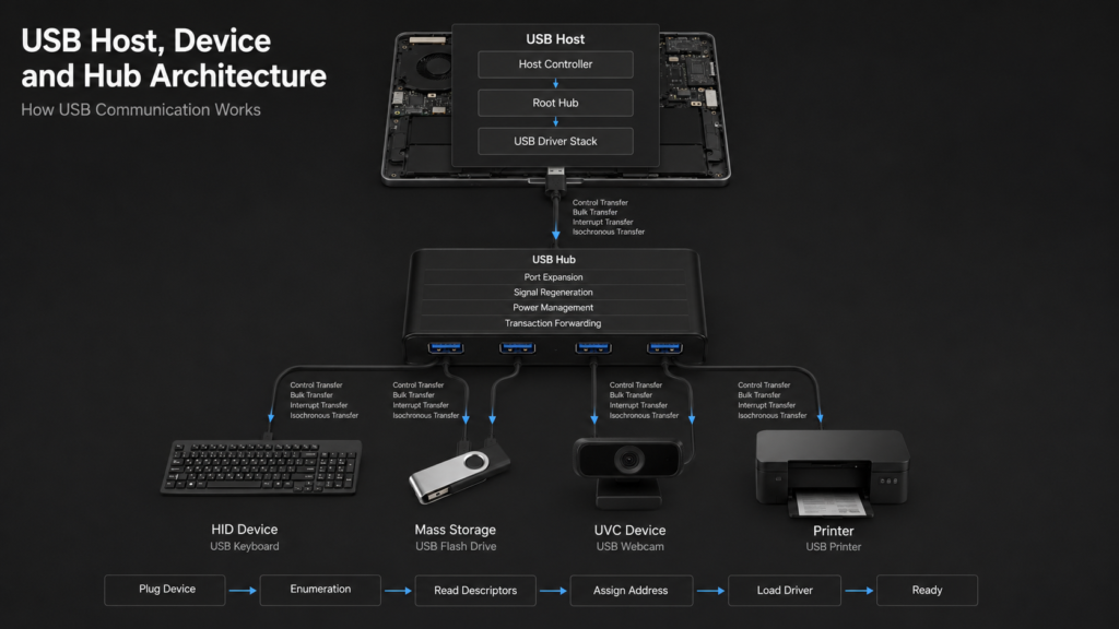
USB uses a host-controlled architecture. Devices on the bus do not communicate freely with each other, and they normally cannot initiate bus transactions on their own. The USB host owns the scheduling authority. A device can only respond when the host polls it or sends a request.
A typical USB system contains three major roles:
| Role | Responsibility |
|---|---|
| USB Host | Controls bus communication, assigns addresses, and schedules transfers |
| USB Device | Provides a specific function, such as a keyboard, flash drive, or camera |
| USB Hub | Expands port count, forwards transactions, and manages downstream devices |
USB connections form a tree topology. The host usually contains an internal root hub, which exposes one or more physical ports. External hubs can be connected to these ports, and more devices or hubs can be connected downstream.
The USB specification supports up to 127 device addresses and a maximum topology depth of 7 tiers, with the root hub counted as the first tier. This layered structure makes expansion easy, but it also means the host must maintain the entire USB device tree.
The host needs to know which ports have devices attached, what speeds those devices support, which drivers should be loaded, and which endpoints are available for communication.
2. USB Protocol Basics: Transfers and Enumeration
USB communication is not a simple byte stream. It is organized around transfer types, endpoints, and transactions. The four common USB transfer types are:
| Transfer Type | Typical Use | Key Characteristics |
|---|---|---|
| Control Transfer | Enumeration, configuration, standard requests | Required by every USB device |
| Bulk Transfer | Flash drives, printers, large data blocks | Reliable, but no fixed latency guarantee |
| Interrupt Transfer | Keyboards, mice, touch devices | Small data, low latency, periodic polling |
| Isochronous Transfer | Audio, video, real-time capture | Guaranteed bandwidth and timing, but allows limited errors |
When a device is plugged in, the host does not use it immediately. It first performs enumeration, which is the process of discovering and configuring the device.
After detecting a port status change, the host resets the device, reads its device descriptor through the default address, obtains information such as VID, PID, device class, and configuration count, assigns a unique USB address, then reads configuration, interface, and endpoint descriptors. Finally, the operating system selects a suitable driver.
Only after enumeration is complete does the device become usable. For example, a USB flash drive may be recognized as a Mass Storage device, a keyboard as a HID device, and a camera as a video-class or composite device.
3. USB Host: The Bus Scheduler
A USB host consists of the host controller hardware, the root hub, and the operating system USB driver stack. Its core responsibility is to control the communication timing of the bus, not to passively receive data from devices.
3.1 Host Controller
The host controller is the hardware execution unit for USB communication. It generates start-of-frame packets, schedules transfer transactions, handles packet transmission and reception, and maintains bus timing.
Different USB generations have used different controller standards:
- OHCI / UHCI: Mainly associated with USB 1.1, supporting low-speed and full-speed devices.
- EHCI: Mainly associated with USB 2.0, supporting high-speed transfers.
- xHCI: Designed for USB 3.0 and later, while also supporting earlier USB versions. It is the mainstream controller architecture on modern platforms.
From a software perspective, the operating system does not directly operate a USB flash drive port. Instead, it submits transfer requests through the host controller driver. The controller then performs the actual bus transactions according to the USB protocol.
3.2 Root Hub
The root hub is integrated inside the host and acts as the starting point of the USB device tree. The USB ports on a computer are usually provided by the root hub or by hubs connected downstream from it.
The root hub detects device attachment and removal, controls port reset, identifies connection speed, and manages port power. Modern USB ports may also support over-current protection, selective suspend, and remote wakeup.
From the operating system’s point of view, each port is an independently manageable object.
3.3 Driver Stack
The USB driver stack is usually divided into two layers: the USB core driver layer and the device class driver layer.
The USB core handles common bus operations such as enumeration, address assignment, device object creation, and transfer management. Device class drivers handle function-specific protocols.
For example, keyboards and mice usually use HID class drivers, flash drives use Mass Storage class drivers, and cameras may use UVC drivers. If a device uses a vendor-specific protocol, it may require a vendor-supplied driver or access through a user-mode interface.
4. USB Devices: Declaring Capabilities Through Descriptors
USB devices are not identified only by their physical appearance. They use standardized descriptors to tell the host who they are, what capabilities they provide, and how the host should communicate with them.
A typical descriptor hierarchy looks like this:
| Descriptor | Description |
|---|---|
| Device Descriptor | Describes overall device information, such as VID, PID, and USB version |
| Configuration Descriptor | Describes one operating configuration, including power attributes and interface count |
| Interface Descriptor | Describes a specific function, such as keyboard, audio, or video |
| Endpoint Descriptor | Describes endpoint direction, type, maximum packet size, and related attributes |
VID and PID are important identifiers for driver matching. VID is assigned to a vendor by the USB organization, while PID is defined by the vendor for a specific product. Operating systems often use VID, PID, device class, and interface class information to select the correct driver.
4.1 Function Devices and Composite Devices
A function device provides one main capability, such as a mouse, flash drive, or USB-to-serial adapter.
A composite device contains multiple functions within one physical device. For example, a webcam with a microphone may contain a video interface, an audio interface, and a control interface.
The key concept behind composite devices is the interface. The host can load different drivers for different interfaces, so a single physical device can appear as multiple logical functions in the operating system.
4.2 Endpoints and Pipes
An endpoint is a data source or sink inside a USB device. Each endpoint has a direction and a type.
IN means data flows from the device to the host, while OUT means data flows from the host to the device. The direction is defined from the host’s perspective, so an IN endpoint means “input to the host,” not “input to the device.”
The logical communication channel between the host and a device endpoint is called a pipe. Endpoint 0 is the default control endpoint that every USB device must provide. It is used for enumeration and standard control requests.
Other endpoints are assigned according to device functions and may use bulk, interrupt, or isochronous transfers.
5. USB Hubs: Expanding Ports and Preserving Connection Quality
A hub appears to turn one USB port into multiple ports, but it is more than a simple splitter. It detects downstream port status, reports attach and detach events, forwards USB transactions, regenerates signals, and handles power and over-current protection.
By power source, hubs are usually divided into two types:
| Hub Type | Characteristics | Typical Use |
|---|---|---|
| Bus-powered hub | Draws power from the upstream USB port; downstream current is limited | Keyboards, mice, card readers, and other low-power devices |
| Self-powered hub | Uses an external power supply and can provide more current to multiple ports | Portable hard drives and multiple high-power peripherals |
In USB 2.0, when the upstream connection is high-speed but a downstream device is low-speed or full-speed, the hub uses a Transaction Translator, or TT, to perform speed conversion.
The TT allows high-speed bus traffic and lower-speed devices to coexist without letting slow devices consume too much high-speed bus time.
Hubs also participate in power management. A more capable hub can switch power per port and shut down an abnormal port when over-current is detected, preventing one faulty device from affecting the entire bus.
6. What Happens When a USB Device Is Plugged In
Using a USB flash drive as an example, the system usually goes through the following process:
- 1.The root hub or external hub detects a port status change.
- 2.The host reads the port status and determines that a new device is attached.
- 3.The host resets the port and identifies the device speed.
- 4.The host reads the device descriptor through a control transfer.
- 5.The host assigns a unique USB address to the device.
- 6.The host continues reading configuration, interface, and endpoint descriptors.
- 7.The operating system matches a driver based on device class, VID, PID, and related information.
- 8.The driver establishes pipes and starts bulk, interrupt, or isochronous transfers as needed.
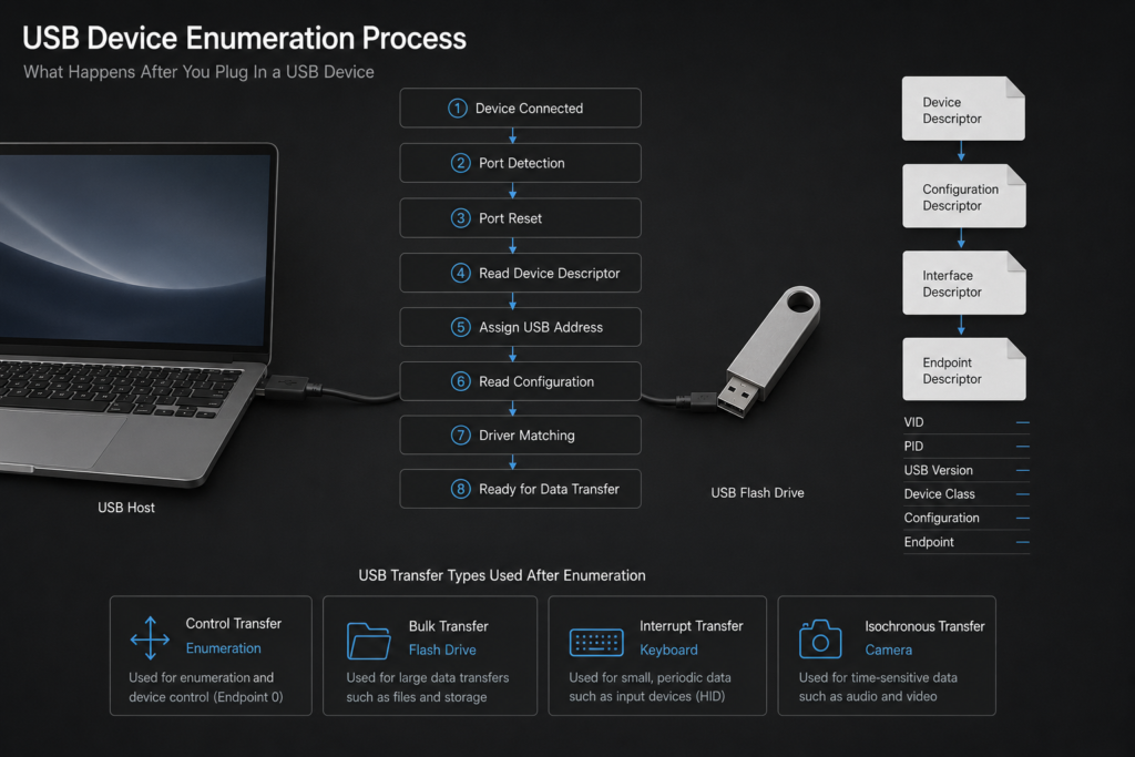
This sequence explains why USB feels like “plug and play” from the user’s perspective. Behind that experience, the host, hub, device, and driver stack cooperate through a well-defined set of protocol operations.
7. Key Technical Takeaways
First, USB is not peer-to-peer communication. Bus control always belongs to the host. Even when a device appears to report data actively, the transfer still depends on host-side scheduling.
Second, descriptors are the core of the USB device model. The host does not identify devices by guesswork. It builds device objects and loads drivers based on the capabilities declared by the device.
Third, endpoints define how data flows. Understanding endpoint direction, transfer type, and pipe relationships is more important than simply memorizing USB connector shapes.
Fourth, a hub is not just an extension cable. It participates in port detection, transaction forwarding, speed coordination, and power management. It is the reason USB topology can expand through multiple tiers.
Fifth, USB version upgrades involve more than higher speed. They also affect host controller architecture, transfer scheduling, signal encoding, and power capabilities.
When troubleshooting USB problems, it is often necessary to consider protocol version, cable quality, power budget, hub type, and driver support together.
Summary
A stable USB system depends on clear role separation. The host schedules and manages the bus. The device declares its capabilities and responds to requests. The hub expands the topology and maintains downstream connections.
Enumeration lets the host discover the device, descriptors standardize device capabilities, and endpoints plus pipes provide clear paths for data transfer.
For development, debugging, or troubleshooting, the most useful mental model is this: after a device is plugged in, the host detects the connection through a hub, completes enumeration through control transfers, matches a driver based on descriptors, and finally exchanges data through endpoints and pipes.
Once this chain is clear, the relationship between USB hosts, devices, and hubs becomes much easier to understand.