
USB is often understood as a simple plug-and-play interface, but behind that convenience is a layered architecture that combines electrical signaling, packet-based communication, transaction handling, and high-level protocol control.
To understand how USB really works, it is helpful to divide it into three major layers: the physical layer, the data layer, and the protocol layer. Each layer solves a different problem, from transmitting electrical signals on the cable to identifying a device and establishing communication pipes.
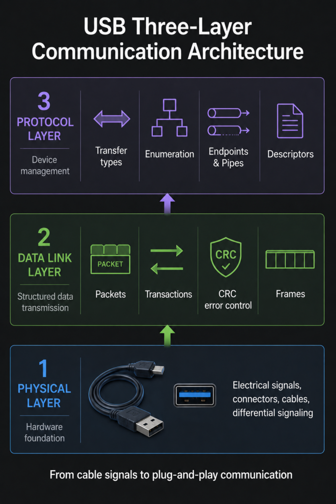
1. Physical Layer
The physical layer defines how USB signals are carried over wires, how devices receive power, what connectors and cables look like, and how signal integrity is maintained. It is the foundation of the entire USB communication system.
1.1 Electrical Characteristics
USB uses differential signaling on the D+ and D- lines. Instead of representing logic values with a single voltage level referenced to ground, USB uses the voltage difference between the two signal lines to represent logical states.
This differential design improves noise immunity and makes USB more reliable in real-world environments where electromagnetic interference may exist.
For USB 1.x and USB 2.0, the common signaling speeds are:
| Speed Mode | Data Rate | Typical Usage |
|---|---|---|
| Low Speed | 1.5 Mbps | Keyboard, mouse, simple HID devices |
| Full Speed | 12 Mbps | Audio devices, embedded devices, legacy peripherals |
| High Speed | 480 Mbps | USB flash drives, cameras, scanners, high-speed peripherals |
USB also provides power through the VBUS line, typically at 5V. Devices can draw power from the bus, and they can also support power-saving states such as suspend and remote wakeup. This allows USB devices to reduce power consumption while still being able to wake the host or resume operation when needed.
1.2 Mechanical Characteristics
The mechanical part of USB defines connector types, pin assignments, shielding requirements, and insertion durability. Classic USB connectors include Standard-A, Standard-B, Mini-USB, and Micro-USB. Each connector type was designed for different device roles and physical size requirements.
For example, Standard-A connectors are commonly used on host-side ports, while Standard-B and Micro-USB connectors were widely used on device-side interfaces. The connector design also includes shielding to reduce electromagnetic interference and improve connection stability.
1.3 Cable and Impedance
USB cables are not ordinary wires. The D+ and D- signal lines are usually arranged as a twisted pair to reduce electromagnetic interference and maintain signal quality.
For USB 2.0 high-speed communication, cable impedance is an important electrical requirement. The differential impedance is typically around 90Ω ±15%. If impedance is poorly controlled, signal reflection, distortion, and data errors may occur, especially at higher speeds.
1.4 Signal Encoding and Synchronization
USB uses NRZI encoding together with bit stuffing. In NRZI encoding, signal transitions and non-transitions are used to represent data rather than directly mapping every bit to a voltage level.
To keep the receiver synchronized, USB inserts a 0 after six consecutive 1 bits. This process is called bit stuffing. It prevents the signal from staying unchanged for too long, which helps the receiver’s clock recovery circuit stay locked to the incoming data stream.
2. Data Layer
The data layer defines how raw signals are organized into packets, how transactions are completed, and how errors are detected. This layer turns electrical signaling into structured USB communication.
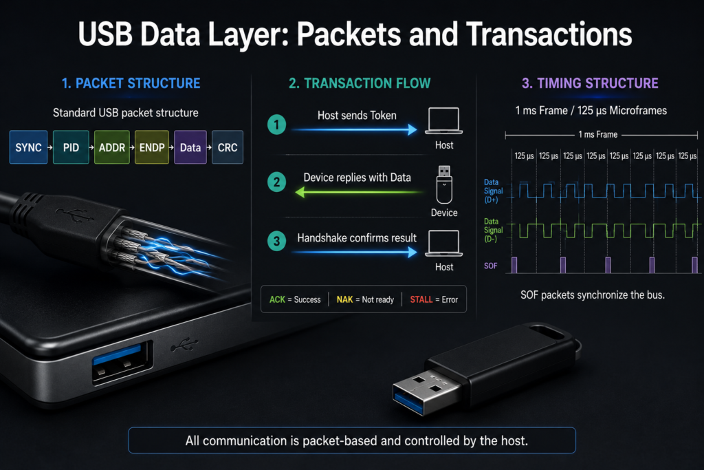
2.1 Packet Structure
USB communication is packet-based. A USB packet may contain fields such as SYNC, PID, ADDR, ENDP, data payload, and CRC.
The PID, or Packet Identifier, indicates the type of packet. Common USB packet categories include:
| Packet Type | Purpose |
|---|---|
| Token Packet | Indicates the target device address, endpoint, and transfer direction |
| Data Packet | Carries actual payload data |
| Handshake Packet | Reports transfer status, such as ACK, NAK, or STALL |
| Special Packet | Used for specific protocol-level functions |
This packet structure allows the host and device to communicate in a predictable and controlled way.
2.2 Transaction Handling
USB follows a host-driven transaction model. A typical transaction starts when the host sends a token packet. The device then responds with a data packet or status information, followed by a handshake packet when required.
For example, in an IN transaction, the host asks a device endpoint to send data. In an OUT transaction, the host sends data to a device endpoint. The device does not freely transmit data whenever it wants; it responds according to the host’s scheduling.
This design is one of the most important characteristics of USB: the host controls the bus, while devices respond to host-initiated requests.
2.3 Error Control
USB includes built-in error detection mechanisms. Token packets use CRC5, while data packets use CRC16. These CRC fields allow the receiver to detect corrupted packets.
Handshake packets indicate the result of a transaction:
| Handshake | Meaning |
|---|---|
| ACK | The packet was received successfully |
| NAK | The device is not ready or has no data available |
| STALL | The endpoint cannot complete the request or is halted |
For transfer types that require reliability, USB can retry failed transactions. For real-time transfers such as isochronous audio or video, retransmission is usually not used because timing is more important than perfect delivery.
2.4 Frames and Microframes
USB uses frames to divide bus time. For low-speed and full-speed communication, one frame is 1 ms. For high-speed communication, each frame is further divided into eight microframes, and each microframe is 125 μs.
The host sends a Start of Frame, or SOF, packet to synchronize devices and organize bus timing. This timing structure allows the host to allocate bandwidth to different devices and transfer types.
3. Protocol Layer
The protocol layer defines how USB devices are configured, how endpoints are used, how different transfer types behave, and how standard requests make plug-and-play possible.
3.1 Transfer Types
USB defines four major transfer types. Each type is designed for a different communication requirement.
| Transfer Type | Main Purpose | Typical Devices |
|---|---|---|
| Control Transfer | Device setup, configuration, and standard requests | All USB devices |
| Bulk Transfer | Large data transfer without strict timing requirements | Printers, scanners, flash drives |
| Interrupt Transfer | Small data with bounded latency | Keyboards, mice, HID devices |
| Isochronous Transfer | Real-time data with guaranteed bandwidth | Audio and video streaming devices |
Control transfers are used during enumeration and configuration. They include setup, data, and status stages, and every USB device must support control transfers through endpoint 0.
Bulk transfers are used when reliability matters more than timing. They support error detection and retry, making them suitable for devices such as printers, scanners, and storage devices.
Interrupt transfers are used for small, time-sensitive data. A keyboard or mouse does not send large amounts of data, but it needs low-latency response, so interrupt transfer is a good fit.
Isochronous transfers are designed for real-time streams. They reserve bandwidth and maintain timing, but they usually do not retry corrupted data. For audio and video, late data may be worse than slightly imperfect data.
3.2 Device Enumeration
Device enumeration is the process that allows the host to discover and configure a newly attached USB device.
When a device is plugged in, the host detects the connection, resets the port, reads the device descriptor, assigns a unique USB address, reads configuration and interface information, loads the appropriate driver, and finally establishes communication pipes.
This process is the technical foundation behind USB plug-and-play. From the user’s perspective, the device simply becomes available. Internally, the host has already completed a structured discovery and configuration process.
3.3 Endpoints and Pipes
An endpoint is a communication target inside a USB device. Each endpoint has a direction and a transfer type. A USB device can have up to 16 endpoint numbers, and each endpoint number can have IN and OUT directions, depending on device implementation.
Endpoint 0 is special. It is the default control endpoint and is required by every USB device. It is used during enumeration and for standard control requests.
A pipe is the logical communication channel between the host and an endpoint. Once the host understands the device’s descriptors, it can create pipes for bulk, interrupt, isochronous, or control communication.
3.4 Standard Requests and Descriptors
USB standard requests allow the host to communicate with devices in a consistent way. Common requests include GetDescriptor, SetAddress, and SetConfiguration.
Descriptors are structured data blocks that describe the device’s identity, configuration, interfaces, and endpoints. Through descriptors, the host learns what the device is, how much power it needs, which interfaces it provides, and how data should be transferred.
This standardized request-and-descriptor mechanism is one of the reasons USB can support so many different device types while still offering a consistent plug-and-play experience.
Summary
USB can be understood as a layered system. The physical layer handles electrical signaling, connectors, cables, impedance, and synchronization. The data layer organizes communication into packets, transactions, frames, and error-control mechanisms. The protocol layer defines transfer types, enumeration, endpoints, pipes, standard requests, and descriptors.
These layers work together to turn a simple user action, plugging in a USB device, into a complete communication process. The host detects the device, resets the port, reads descriptors, assigns an address, configures the device, loads the driver, and finally exchanges data through endpoints and pipes.
Once this layered model is clear, USB becomes much easier to understand. It is not just a connector or a cable standard; it is a complete communication architecture that combines hardware signaling, packet-level reliability, and protocol-level device management.