
Have you ever had this experience: you bought a so-called “full-feature USB-C cable”, but when you connect your laptop to a monitor, it only charges and the screen stays completely black; when transferring files to a portable hard drive, the speed is only a few MB/s, but it works normally when you switch to an old cable? Most of these problems come from the invisible internal wiring of the cable — even cables with USB-C connectors may only have power wires and necessary identification components reserved for charging, and some even have non-standard wire-saving designs; they may also contain multiple sets of high-speed differential pairs and auxiliary wires, with a capability gap of more than ten times. The USB-C cable wiring schematic is a tool to help you see “what exactly is connected inside the cable”. This article starts with the basics of how to read these diagrams, helping you independently judge the power, data rate, and video support capabilities of cables, and also troubleshoot common faults.
1. Beginner Prerequisites: What Exactly Do You Look for in a USB-C Cable Wiring Schematic?
A USB-C cable wiring schematic shows the functional connection relationship between the internal wires of the cable and the contacts (pins) of the USB-C plugs at both ends. It is not a cable appearance drawing, nor a precise PCB engineering drawing. Its core function is to let readers quickly see which functional circuits are actually connected, rather than getting tangled up in production details. The core goal of reading the diagram is to judge which capabilities a cable roughly supports among charging, USB 2.0 data, high-speed data, video output, and USB4/Thunderbolt.
Many people confuse it with two other types of diagrams, so let’s clarify the boundaries first:
- USB-C pin definition diagram: Focuses on explaining the names and functions of the 24 contacts on the interface, equivalent to the “interface function manual”;
- Type-C wire sequence diagram: Focuses on emphasizing the corresponding order and one-to-one relationship of each wire from one end to the other, more of a reference for production wiring;
- USB-C cable wiring schematic: Geared toward ordinary users for capability judgment, usually merges contacts with duplicate functions, does not necessarily draw all 24 pins, and focuses on functions rather than wiring details.
Understanding wiring schematics has high practical value: when buying a cable, you can judge whether claims like “100W”, “full-feature”, “40Gbps” have a basis; when encountering problems like “only charges but cannot transfer files”, “monitor has no picture”, “hard drive speed is slow”, you can quickly locate whether the problem is with the cable; you can also understand why cables with the same USB-C interface have such large capability differences.
At the beginner stage, you must first distinguish three basic concepts to avoid going astray later:
First, interface is not equal to cable: The USB-C port on the device determines the upper limit of the device’s own capabilities, and the internal wiring of the cable determines the upper limit of transmission capability. The two must match to achieve full performance;
Second, same appearance does not equal same function: USB-C is just a physical interface form. Internally, it may be a USB 2.0 cable, high-speed data cable, full-feature cable, or USB4/Thunderbolt cable. There is no way to tell the difference just from the appearance;
Third, being able to plug in does not equal being able to run at full speed: Charging power, transmission rate, and video resolution all require the device, cable, and peripheral to support the corresponding specification at the same time. If any one is missing, it will run at the lowest specification.
2. Essentials for Reading Diagrams: Plain-Language Grouping of USB-C Pin Functions
To understand wiring diagrams, you don’t have to memorize the numbers of the 24 pins by rote. Just divide them into 5 groups by function, each responsible for one type of work, which is easy to remember.
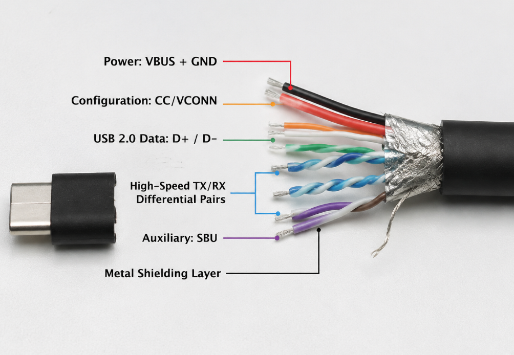
First, let’s talk about the basic structure of the USB-C interface: a standard USB-C interface has up to 24 contacts, 12 on each of the upper and lower rows, approximately symmetrical, so it supports reversible plugging. But reversible plugging is not achieved by making two complete sets of circuits inside the cable — that would be too costly. Instead, it is achieved through the symmetrical pin layout, direction identification via CC pins, plus a channel switching chip on the device side. The cable does not need double the wires. For this reason, wiring schematics often merge multiple pins with the same function into one group. For example, multiple VBUS and multiple GND pins may be drawn as a single thick line, which does not mean only one contact is connected.
1. Power Supply Category: VBUS and GND
This is the easiest group to understand, equivalent to the positive and negative poles of a wire.
- VBUS: Power supply positive. Basic USB power supply starts at 5V. After negotiation via USB PD fast charging, it can rise to 9V, 12V, 20V or even higher voltages, corresponding to higher power. The specific voltage levels that can be negotiated depend on the USB PD version, charger, device, and cable capabilities; higher voltage levels are only involved in PD 3.1 EPR scenarios.
- GND: Ground wire. On the one hand, it forms a current loop for normal power transmission; on the other hand, it serves as a reference baseline for all signals.
When looking at wiring diagrams, power wires are usually drawn relatively thick. Special attention should be paid here: the metal shielding layer (Shield) outside the cable is not equivalent to GND. The shielding layer is mainly used to resist external electromagnetic interference. Although it is sometimes connected to GND, its function is completely different, and the shielding layer is especially important for high-speed cables.
2. Configuration Negotiation Category: CC and VCONN
CC (Configuration Channel) is a dedicated negotiation path between the cable and the device: when plugged in, it is responsible for detecting the insertion status, identifying the plug direction, and also undertaking USB PD power supply negotiation and cable capability reporting (such as information from the E-Marker chip).
Many people think that there are two independent CC wires in a C-to-C cable, but in fact, there is usually only one CC wire inside a C-C cable for connecting both ends; after insertion, the device judges the insertion direction based on the CC1/CC2 pins on the interface side, and the side not used for CC communication can be provided with VCONN by the power supply end to power the internal chips of the cable (such as E-Marker). VCONN is not an additional fixed independent functional wire inside the cable, but is undertaken part-time by the CC pin on the interface side.
As for cables with USB-A on one end and USB-C on the other, they are not without CC function. Instead, an Rp resistor is set in the C-port plug to declare the current capability to the device, preventing the device from drawing more power than the cable can withstand.
3. Low-Speed Data Category: D+ and D-
This pair of wires is what we commonly call USB 2.0 data wires, which have been in use for more than 20 years.
D+/D- are responsible for USB 2.0 data transmission, with a theoretical maximum rate of 480Mbps, which is sufficient for transferring photos to mobile phones, connecting keyboards, mice, and printers. Many original mobile phone charging cables have this pair of wires connected, so they can transfer files, but the speed is not high.
Some early proprietary fast charging protocols (such as old versions of Qualcomm QC and other manufacturer proprietary protocols) used D+/D- to identify chargers, but current USB PD fast charging mainly relies on CC communication and has nothing to do with D+/D-.
4. High-Speed Data Category: TX/RX Differential Pairs
These are the “fast lanes” for high-speed data. USB 3.x, USB4, Thunderbolt, and DisplayPort video output all rely on these wires for transmission.
Why are they called differential pairs? Because high-speed signals are particularly susceptible to interference, two wires are used to transmit the positive and negative phases of the same signal, and finally the signal is restored by the difference, which greatly improves anti-interference ability. TX is transmit and RX is receive, so they always appear in pairs.
The Type-C interface has multiple sets of TX/RX differential pairs prepared for reversible plugging and multi-channel high-speed transmission. TX1/RX1, TX2/RX2 or Lane labels are common in wiring diagrams. Schematics may merge similar differential pairs for display, so you cannot judge the real high-speed capability only by the number of lines drawn. Reversible plugging switching is completed by the channel chip on the device side, not because the cable only connects half of the circuits. Different types of cables have different numbers of high-speed wires: C-C high-speed cables will connect all required differential pairs according to specifications, while some A-C cables or cables with simplified designs have fewer high-speed wires. You cannot assume it is a complete high-speed C-C cable just because you see TX/RX.
When looking at high-speed wires, you can’t just look at “whether they are connected”; you also need to look at cable length, impedance control, shielding process, wire quality, and certification — high-speed signals have much higher requirements for circuit quality than low-speed signals.
5. Auxiliary Category: SBU and Shield
The last group is auxiliary function pins, which are not usually used and only activated in specific scenarios.
- SBU: Full name is Sideband Use, mainly used for HPD hot-plug detection and AUX configuration signal transmission under DisplayPort Alt Mode, and also used in special modes such as some audio adapters. Ordinary USB 2.0 or pure charging cables generally do not have SBU connected, so they cannot support standard video output.
- Shield (shielding layer): Although it is not a pin, it is particularly important for high-speed data and video. It is equivalent to putting a metal cover over all signal wires, which not only blocks external interference but also prevents internal signals from leaking out and affecting other devices. Cheap high-speed cables often cut corners on shielding, leading to easy disconnection, screen flickering, and slow speed during use.
3. How to Read Diagrams: 4 Steps to Understand Any USB-C Cable Wiring Schematic
Now that you know these functional groups, you won’t be confused when looking at any USB-C cable wiring schematic, as long as you follow four steps.
Step 1: First confirm the cable type
Different types of cables have completely different wiring rules. You cannot use the standard of C-to-C straight-through cables to require adapter cables.
- C-to-C straight-through cable: Both ends are USB-C plugs, and the internal wires directly connect the contacts at both ends. Most of the PD charging cables, high-speed data cables, full-feature cables, and Thunderbolt cables we usually talk about are of this type.
- A-to-C cable: One end is USB-A, the other is USB-C. It is commonly used for old chargers and old computers connecting to mobile phones. This type of cable has no CC pin on the USB-A end, so it cannot support complete PD fast charging negotiation, and only relies on the resistor on the C end to declare current capability.
- C-to-HDMI/DP/Ethernet etc. adapter cables: This type of cable generally has a protocol conversion chip inside, not a simple straight-through, so you cannot judge the capability only by the wiring diagram; you also need to look at the specifications supported by the chip.
- Active cable: Generally longer high-speed cables or Thunderbolt cables, with built-in signal amplification and re-timing chips, which can make high-speed signals travel farther. However, this type of cable may have direction requirements, and may be limited by chip capability under specific protocols, rates, or cable lengths. You cannot judge only by the thickness of the cable.
Step 2: Then check whether the four types of functional wires are present
After confirming the type, check which categories of functional wires this cable has: power wires (VBUS+GND), negotiation wires (CC/VCONN), data wires (D+/D-+TX/RX), auxiliary wires (SBU+shield).
Each additional category adds another layer of function: if there are only power and negotiation wires, it is a pure charging cable — this type of cable cannot be understood as a complete USB-C data cable, and whether it can stably support PD fast charging depends on whether the CC, current declaration, and cable design are standardized. If it is a C-C cable, if it lacks D+/D-, you cannot expect USB 2.0 data. This type of wire-saving design should be treated as a dedicated charging cable or a risky product, and should not be purchased as a general-purpose data cable. With D+/D- added, it can transmit USB 2.0 data; with high-speed TX/RX added, it can run high-speed data; with SBU and complete shielding added, it is possible to support video output.
Step 3: Verify the connection method and omission rules
Many people are confused when looking at wiring diagrams: “Didn’t they say USB-C has 24 pins? Why are there only a few wires in the diagram?” In fact, schematics omit many duplicate parts for ease of understanding:
- Multiple VBUS and GND contacts are often merged into a single thick line because they have the same function, which does not mean only one contact is connected;
- Vertically symmetrical pins, such as TX1/RX1 on the upper row and TX2/RX2 on the lower row, are sometimes only drawn on one side, with a label like “mirror connection” or “reversible plug symmetry” next to it, meaning the pin connection on the other side is the same;
- Pins not drawn are not necessarily unconnected, but if pins related to the function you need (for example, SBU is not drawn when you need video output) are not marked, you should be careful — either they are not connected, or the merchant deliberately omitted them.
A special reminder here: If a diagram only draws the 24 pins of the USB-C interface but does not draw which wires are connected inside, this diagram has no practical reference value — it can only tell you what the interface looks like, and cannot prove what the cable is connected to.
Step 4: Finally judge by the upper limit of capability
The last step is to judge what this cable can do at most based on which wires are connected:
- Only VBUS/GND/CC: At most, it can only charge and be identified by the device; data and video capabilities are not guaranteed;
- Has D+/D-: At least supports USB 2.0 data, no problem with transferring files and connecting ordinary peripherals;
- Has complete high-speed differential pairs and shielding: Only then is it possible to support USB 3.x, USB4, Thunderbolt, or high-resolution video;
- Has E-Marker: It means this cable can report its own capabilities through CC, but it also depends on the specific content of the report — whether it is 5A current, 40Gbps rate, or Thunderbolt capability. You cannot assume it is a full-feature cable just because you see a chip.
4. Comparison of Common USB-C Cable Wiring Examples
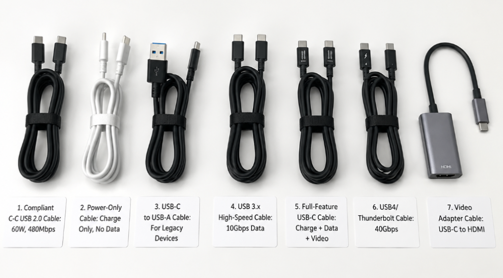
For your convenience in comparison, I have organized the typical wiring, functions, and precautions of the 7 most common USB-C cables into a table, which you can directly check when buying cables or troubleshooting:
| Cable Type | Wiring Features | Core Functions | Common Uses | Precautions and Boundaries |
|---|---|---|---|---|
| Compliant C-C USB 2.0 Cable | VBUS, GND, CC, D+/D- | Supports USB 2.0 data (up to 480Mbps), supports USB PD negotiation | Mobile phone charging and file transfer, tablets, earphones, keyboards, printers | Ordinary models support up to 3A/about 60W; higher power requires corresponding E-Marker, EPR, and three-end matching |
| Power-Only/Wire-Saving Type (Risky Model) | Common wire-saving performance: may only retain VBUS/GND and necessary identification design, may also have non-standard connection methods | Cannot guarantee standard USB data capability; whether PD can be triggered stably depends on whether negotiation designs such as CC and current declaration are standardized | Temporary emergency charging | Should not be purchased as a general standard C-C cable; if D+/D- are not drawn, you cannot expect file transfer; when purchasing, confirm whether it is marked “charge only/no data transfer” and the boundaries of PD support |
| USB-C to USB-A Cable | A side: VBUS, GND, D+/D-; C side: CC with Rp resistor | Supports USB 2.0 or USB 3.x data (depends on whether there are high-speed wires) | Old computers connecting to mobile phones, old chargers charging C-port devices | Does not support complete C-C PD negotiation; proprietary fast charging is not the same as USB PD |
| USB 3.x High-Speed Cable | Adds high-speed TX/RX differential pairs + shielding on the basis of USB 2.0 | Supports USB 3.2 Gen1 (5Gbps)/Gen2 (10Gbps)/Gen2x2 (20Gbps) | Portable SSDs, capture cards, docking stations, monitor upstream cables | The rate depends on the controllers of the devices at both ends and the quality of the cable; pay attention to shielding and E-Marker |
| Full-Feature USB-C Cable | Power supply + CC + D+/D- + complete high-speed differential pairs + SBU + shielding, usually with E-Marker | Simultaneously supports charging, USB data, DisplayPort Alt Mode video | Monitor one-cable connection, docking stations, laptop charging + video output | The specific power and rate upper limits are subject to certification and labeling; full-feature ≠ 240W ≠ 40Gbps |
| USB4/Thunderbolt Cable | High-speed differential pairs + CC + E-Marker, active long cables have built-in signal chips | Can support 20Gbps or 40Gbps level transmission; higher capabilities only apply to scenarios where corresponding new specifications, certified cables, and devices at both ends are supported at the same time. Compatibility with USB/DP capabilities also depends on the host, peripherals, and cable declarations. | High-speed docking stations, external graphics cards, Thunderbolt storage | Power is not fixed; need to check certification, nominal rate, active/passive type, and length limits |
| Video Adapter Cable/Special Function Cable | Built-in protocol conversion chip, wiring is not straight-through | Conversion functions such as C to HDMI/DP/Ethernet | Old monitors, wired network port expansion | Capability depends on chip and device Alt Mode support; cannot be judged by straight-through cable rules |
The above are the conventional situations of typical straight-through cables. The specific capabilities are subject to the cable’s nominal specifications and certification information, and absolute conclusions cannot be drawn solely from the wiring diagram.
5. Advanced Judgment: Infer Charging Capability from Wiring Diagrams
Charging is the function everyone cares about most. How to judge how much power a cable can support from the wiring diagram? The core depends on three points: whether the power supply path is complete, whether the current capability is sufficient, and whether there is a corresponding negotiation mechanism.
First check if the basic power supply path exists
First of all, VBUS and GND must be fully connected. This is the basis of charging; without them, even electricity cannot pass through.
Secondly, C-to-C cables must also have CC pins, because CC is responsible for insertion identification, device role judgment, and PD negotiation — if CC is abnormal, problems such as inability to fast charge, inability to identify direction, repeated disconnection of the device, or even complete failure to charge may occur.
Judge by power tiers
The core of power is current. Voltage is negotiated, but current is the hard upper limit of the cable:
- Within 3A (about 60W): Compliant C-C cables can usually declare a maximum current of 3A, which corresponds to about 60W of power calculated at 20V. It is sufficient for daily charging of mobile phones, tablets, and thin and light laptops. The actual power is still determined by the negotiation of the charger, cable, and device.
- 5A/100W: A cable that supports 5A must be used, and it must have an E-Marker chip, otherwise the device will not dare to output 5A current for fear of burning the cable. This type of cable is usually clearly marked “5A” “100W PD”.
- 240W level: The commonly advertised 240W belongs to USB PD 3.1 EPR (Extended Power Range). It not only requires the cable to support 5A current and 48V withstand voltage, but also requires the charger and device to support EPR at the same time. All three are indispensable, and it cannot be judged solely by “thick cable”.
Look at wire gauge but don’t only trust wire gauge
Many people look at “whether the cable is thick” when buying charging cables. A thicker cable is indeed easier to pass larger currents. Professionally, it is expressed in AWG (American Wire Gauge). The smaller the value, the thicker the wire. For example, 24AWG wire is thicker than 28AWG, with smaller voltage drop and less heat generation.
But wire gauge is only one of the judgment conditions. You also need to look at cable length, copper purity, terminal welding quality, temperature rise control, and official certification. You cannot judge power capability solely by the thickness of the appearance. For methods of identifying false labeling of high-power and high-speed cables, please refer to the systematic explanation in Chapter 7 later.
Final power is determined by three parties together
Also remember that the final charging power is not determined by the cable alone, but is the result of negotiation between the charger, cable, and device. Just like a wooden bucket holding water, the shortest board determines the final capacity:
- The output capability of the charger is one of the upper limits;
- The current capability declared by the cable determines the current level that can be passed;
- The device’s input strategy determines the final actual power used.
For example: if you use a 240W cable to connect a 65W charger to charge a laptop, the maximum is only 65W, it will not charge faster just because the cable is good.
6. Advanced Judgment: Data, Video, and Thunderbolt Capabilities
In addition to charging, data and video capabilities are also often confused by everyone. In fact, as long as you correspond to the corresponding functional wires, it is easy to judge.
Judge USB 2.0 data capability
This is the simplest: you must see D+/D- connected.
If there is no D+/D- in the diagram, then this cable is a pure charging cable, which cannot even transfer photos from a mobile phone, ADB debugging, or connect a keyboard and mouse. The theoretical maximum rate of USB 2.0 is 480Mbps, and actual file transfer is usually lower than the theoretical value. Under ideal conditions, it can reach about tens of MB/s. The specific speed is affected by the storage device, device working mode, system and protocol overhead, and there is no fixed standard value.
Judge USB 3.x high-speed data capability
To support USB 3.x high-speed data, there must be high-speed TX/RX differential pairs, as well as good shielding.
But note: it is not that with differential pairs you can definitely run at high speed. High-speed signals have particularly high requirements for the circuit: impedance must be continuous, no crosstalk, low attenuation. These cannot be measured by a multimeter for continuity. For example, if you measure TX/RX with a multimeter and they are connected, but if the cable’s shielding is poor, or the connector welding is poor resulting in discontinuous impedance, the speed may be less stable than USB 2.0.
In addition, different versions of USB 3.2 (Gen1 5Gbps, Gen2 10Gbps, Gen2x2 20Gbps) not only depend on the cable, but also on whether the controllers of the devices at both ends support it. For example, if you use a 10Gbps cable connected to a computer port that only has 5Gbps, the maximum speed is only 5Gbps.
Judge USB4/Thunderbolt capability
USB4 and Thunderbolt have higher requirements. Not only do they need high-speed differential pairs, but they also need an E-Marker chip to declare the corresponding rate capability. When judging Thunderbolt capability, you should check the Thunderbolt certification mark, clear rate, and active/passive information; without certification or clear nominal value, Thunderbolt-level stable performance should not be promised.
Many people think that having an E-Marker means it is a Thunderbolt cable, but that is not the case — E-Marker is only used to report cable capabilities, and may only declare 5A current level, not necessarily support high-speed or Thunderbolt specifications (for specific misunderstandings, please refer to the summary of common misunderstandings later). When purchasing, focus on checking the nominal rate, active/passive type, and USB4/Thunderbolt certification marks. Passive 40Gbps cables are usually short in length. Increased length will greatly increase the requirements for wire quality and shielding process. Long-distance high-speed cables mostly use active design (built-in signal amplification/re-timing chips).
Judge video output capability
The most common video output of USB-C is DisplayPort Alt Mode (DP Alternate Mode), which is equivalent to borrowing the high-speed differential pairs in USB-C to transmit video signals. In this mode, not only high-speed differential pairs are required, but also SBU auxiliary channels to transmit control signals. Common standard DP Alt Mode usually requires SBU to carry auxiliary signals such as AUX/HPD; if the wiring diagram does not have SBU, complete video Alt Mode capability should not be advertised.
There are two other common modes for video output:
- 2-Lane mode: Uses two sets of high-speed differential pairs to transmit video, and the remaining two sets can still transmit USB 3.x data, so you can plug in a U disk while plugging in the monitor;
- 4-Lane mode: Uses all four sets of high-speed differential pairs to transmit video, which can support higher resolution and refresh rate, but USB data can only run at USB 2.0.
Also note that not all USB-C ports can output video — the device’s C port must support DP Alt Mode, USB4, or Thunderbolt, otherwise no matter how good the cable is, it is useless. Resolution and refresh rate also require the device, cable, and monitor to support the corresponding specifications.
7. Identifying False Advertising and Low-Quality Schematics
Now many merchants put so-called “wiring diagrams” in their promotional pictures, but many are just perfunctory. Here are a few tricks to quickly identify them:
1. Only draw pins without internal connections
This type of diagram just shows you the 24 pins of the USB-C interface, and doesn’t say which wires are connected inside, which proves nothing. When you encounter this situation, directly ask customer service for the internal wiring diagram, or look at the function description in the detailed parameters.
2. Labeled “full-feature” but lacks key wires
For C-C straight-through cables commonly used by ordinary consumers, a full-feature cable must have power supply, negotiation, low-speed data, high-speed data, auxiliary channels, and shielding at the same time. Missing any one cannot cover the complete charging + data + video capabilities. If it is advertised as a full-feature cable, but there is no SBU in the wiring diagram, it definitely cannot support complete video output; without high-speed differential pairs, it cannot even use USB 3.x; without D+/D-, it cannot even do USB 2.0 data.
3. Labeled “100W/240W” but no cable identity information
Nominal high power without marking PD version, rated current, E-Marker support or related certifications has very low credibility. Also don’t judge power only by the thickness of the cable; a thick cable may just have a thick outer sheath, and the internal copper wire may not meet the standard.
4. Labeled “40Gbps” but lacks high-speed conditions
For cables nominally 40Gbps, focus on cable length, active/passive type, USB4/Thunderbolt certification, and E-Marker declaration. Passive 40Gbps cables are usually short. Overly long passive cables without official certification are actually difficult to stably run at full bandwidth, with high risk, and are not recommended for purchase as 40Gbps high-speed cables; products with USB4/Thunderbolt certification, clear cable length, active/passive type, and E-Marker declaration should be prioritized.
5. Be careful with stacked marketing terms
Many merchants pile up a bunch of terms like “full-feature”, “full-blooded”, “8K”, “240W”, “40Gbps” together, which looks very impressive, but in fact these terms belong to different dimensions and may not all be achieved at the same time.
The correct judgment order is: first look at power supply capability, then USB data rate, then video output capability, and finally USB4/Thunderbolt certification. Don’t be fooled by one of the selling points — for example, some 240W cables are actually just high-power charging cables, which don’t even support USB 3.0, let alone 8K video.
8. Troubleshooting Common Cable Faults with Wiring Schematics
If your cable has a problem, you can also troubleshoot it against the wiring diagram, no need to guess blindly.
Pre-troubleshooting preparation
First prepare a few things: a credible cable wiring diagram (preferably official), a multimeter (for measuring continuity), a USB tester (for measuring power), and a few known good cables and devices for cross-testing.
If it is a high-speed data or video problem, it is best to use the cross-test method: change the cable, change the device, change the interface, change the docking station, eliminate one by one, and you can quickly find out where the problem is.
Special reminder: if a high-power cable is broken, never take it apart and repair it yourself. If it is not connected properly, short circuit and heat can easily cause a fire. It is safer to replace it directly.
4-Step Troubleshooting Method
When troubleshooting, follow four steps for the highest efficiency:
- Clarify the fault phenomenon: Is it completely unable to charge? Or can charge but cannot fast charge? Is it unable to transfer files? Or transfers files very slowly? Is the monitor has no picture? Or works when plugged in one way but not the other? Different faults correspond to different functional wires.
- Locate relevant functional wires against the wiring diagram: For example, if it cannot fast charge, check CC, VBUS, GND, and E-Marker; if it cannot transfer USB 2.0 files, check D+/D-; if the portable hard drive is slow, check high-speed TX/RX and shielding; if the monitor has no picture, check high-speed Lane and SBU; if it works one way but not the other when flipped, check CC direction identification or welding of high-speed differential pairs.
- Do continuity or replacement test: If you have a multimeter, you can measure whether the corresponding pins are connected; if not, replace with a known good cable to see if the fault disappears, then you can judge whether it is a cable problem.
- Decide to replace or stop using: In most cases, it is not recommended to repair a broken cable, especially high-power cables and high-speed cables. Repaired cables are prone to problems, and direct replacement is more reliable.
Common faults and possible wiring problems
I have organized the most common faults and corresponding causes, you can directly compare:
- Only charges but cannot transfer files: Most likely D+/D- are broken or not connected, it may also be a device driver or setting problem. First try replacing with a normal cable.
- Can transfer files but the portable hard drive is very slow: It means this cable only has USB 2.0 D+/D-, no high-speed TX/RX differential pairs. Just replace with a high-speed cable.
- Can charge but cannot PD fast charge: It may be poor contact of the CC pin, or the E-Marker chip is broken, or the charger or device does not support the corresponding gear. You can see how much power is negotiated with a USB tester.
- Works normally when plugged in one way, but not when flipped: Either there is a problem with the direction identification of the CC pin, or the welding of the high-speed differential pair on one side is broken. This situation is very common in cheap cables.
- Monitor has no picture: First confirm whether the device’s C port supports video output, then check whether the cable has SBU and high-speed differential pairs, and whether it supports DP Alt Mode. All three are indispensable.
- Video flickering, hard drive frequently disconnects: Mostly due to poor quality of high-speed differential pairs, or cut corners on the shielding layer, or the cable is too long and the signal attenuation is too severe.
Boundaries between repair and replacement
Finally, let’s talk about which situations must be replaced and absolutely cannot be repaired:
- VBUS/GND damage: Especially for high-power cables, if the contact is poor, large current will cause heat or even short circuit when passing through, which has safety hazards. Absolutely do not continue to use for fast charging after self-repair.
- High-speed differential pair damage: Even if you connect them, the impedance will be discontinuous, and high-speed signals will still drop speed and disconnect. It is not as stable as an ordinary cable when used, so there is no need to repair.
- Shielding layer damage: Interference will be very serious, high-speed data and video will be affected, and there is no need to repair.
- Low-value or unknown specification cables: Direct replacement is much more cost-effective than repair, and also safer.
9. Summary of Common Misconceptions
Finally, let’s summarize a few of the most common pitfalls people fall into, don’t be fooled again:
- All USB-C cables have all 24 wires connected: Wrong. The USB-C interface has up to 24 contacts, but the cable is wired according to functional requirements, and the internal wiring of different types of cables varies greatly.
- Supporting 100W/240W means it must support high-speed data: Wrong. High power only has requirements for power wires, CC, and E-Marker, and has nothing to do with high-speed data wires. Many high-power cables only support USB 2.0 data.
- Having an E-Marker means it is a full-feature cable: Wrong. E-Marker is only used to report cable capabilities, and may only declare 5A current, or may declare high-speed or Thunderbolt capabilities. It depends on the specific reported content.
- The thicker the cable, the stronger the function: Wrong. A thick cable may only mean that the power wires are thicker, and does not mean there are high-speed data wires or SBU. Functions depend on the complete wiring and specification labels.
- All USB-C ports can connect to monitors: Wrong. The device’s USB-C port must support DP Alt Mode, USB4, or Thunderbolt to output video. Interfaces that only support charging/data cannot connect to monitors.
- A multimeter measuring continuity means the cable can run at full speed: Wrong. A multimeter can only detect DC continuity. High-speed signals have strict requirements for impedance, crosstalk, attenuation, etc. Normal continuity does not mean that high-speed performance meets the standard.
Capability Checklist After Reading
After reading this article, you should have mastered these practical skills:
Beginner Capabilities
You can distinguish the differences between USB-C interfaces, USB-C cables, pin definition diagrams, and wiring schematics, and you can also recognize core labels such as VBUS, GND, CC, D+/D-, TX/RX, and SBU, and you will no longer be confused by various technical diagrams.
Purchase Judgment Capabilities
You can judge from the wiring diagram whether a cable is for charging, for USB 2.0 data transfer, for high-speed operation, for video connection, or a USB4/Thunderbolt cable; you can also distinguish that parameters such as 100W, 240W, 5Gbps, and 40Gbps belong to different dimensions, and will not be fooled by marketing terms like “full-feature” and “full-blooded”. You know that high power does not equal high speed, and full-feature does not necessarily mean 240W or 40Gbps.
Troubleshooting Capabilities
You can roughly locate which functional wire has a problem based on the fault phenomenon, and you can also use the cross-test method to eliminate basic faults. You know which broken cables must be replaced and cannot be repaired at risk.
In the final analysis, the capability boundary of a USB-C cable is essentially determined by the internal connected functional circuits and the wire craftsmanship. Next time you buy a cable or encounter a fault, you don’t have to guess blindly. Find a reliable wiring schematic to compare and judge, and you’ll have a clear idea.