
If you’ve used devices with a USB-C port, you’ve most likely encountered these odd issues: it charges fine, but there’s no response at all when connecting a monitor; the USB-C to 3.5mm adapter you bought works for listening to music but the microphone doesn’t work; even with the same cable and same port, it works when plugged in one way and fails when flipped. Behind these problems is often a pair of unassuming pins in the USB-C port: SBU.
Many people are unfamiliar with SBU, even thinking it’s a useless unused pin. In fact, it is a key auxiliary channel for USB-C expansion functions. From small analog headphone adapters to large docking stations supporting DP Alt Mode, Thunderbolt, or USB4, SBU or related sideband paths may be involved; it’s just that the mechanisms of Thunderbolt/USB4 are more complex and cannot be simply inferred using ordinary SBU logic. In this article, we will start from the most basic definitions, covering uses in different scenarios, accessory purchasing, troubleshooting, and even pitfalls to avoid in hardware design, to explain SBU thoroughly.
1. Getting to Know SBU: The Auxiliary Sideband Channel in USB-C
1.1 What is SBU
Simply put, SBU refers to two low-speed auxiliary signal lines in the USB-C port reserved specifically for special functions. They are neither power lines nor ordinary USB data lines. Its official name is Sideband Use, often translated as auxiliary channel or sideband channel in Chinese, and the two pins are called SBU1 and SBU2 respectively.
The division of labor for various signals in the USB-C port is very clear: main data (such as file transfer, video images) is transmitted via high-speed differential lines or D+/D-, power supply relies on VBUS and GND pins, and “decision-making work” such as protocol negotiation and insertion detection relies on CC pins. SBU usually starts undertaking corresponding auxiliary signal transmission only after the device has confirmed entry into a specific expansion mode or accessory mode.
1.2 Why Understand SBU
You might say, I usually only use USB-C for charging and file transfer, why do I need to understand SBU? In fact, it is directly related to many common problems:
For ordinary users, understanding SBU can explain many “indescribable small glitches” — for example, charging works but screen mirroring doesn’t, the USB-C to 3.5mm adapter works for music but the microphone doesn’t, the same cable works when plugged in one way but has no response when flipped. These problems are often related to the SBU link.
For accessory purchasing, understanding the function of SBU allows you to quickly distinguish between pure charging cables, USB 2.0 cables, full-featured cables, and Thunderbolt/USB4 cables, and also tell the difference between digital DAC adapters and analog audio adapters, so you don’t have to buy by guesswork.
For hardware design, testing, or maintenance personnel, whether the routing, switching, and protection design of SBU is reasonable directly affects the stability of video, audio, and debugging functions. Incorrect connections, overly long traces, MUX switching errors, and improper ESD component selection can all cause functional abnormalities.
1.3 Functions SBU Is Not Responsible For
Before delving into its uses, first clarifying the capability boundaries of SBU can help you avoid many common misunderstandings:
- It is not a power pin, is not responsible for VBUS power supply, and must never be used as a power line;
- It does not undertake USB PD power negotiation; all PD communication goes through CC pins;
- It is not responsible for ordinary USB 2.0 data transmission; signals from basic USB devices such as USB flash drives and mice usually go through D+/D-;
- It also does not carry high-bandwidth data such as USB 3.x, USB4, or DP video main links; all high-speed main data goes through dedicated high-speed differential lines;
- It is even less equivalent to the shielding layer or chassis ground; the port shielding layer or chassis ground cannot be used to arbitrarily replace the functional connection of SBU.
2. Pin Definition and Working Logic of SBU1/SBU2
2.1 Standard Pin Position
In the standard port of the official USB Type-C specification, SBU1 corresponds to contact A8, and SBU2 corresponds to contact B8. A special reminder here: do not memorize pin positions based on subjective perspectives such as “top row on the front” or “front row on the reverse”, because the perspectives of different connector packages and PCB designs may be completely different. You must always refer to the USB-IF specification, connector datasheet, and actual PCB package.
When doing hardware design or maintenance, you must ensure that the schematic symbol, PCB package, and actual connector pin positions are consistent. Once A8/B8 are misaligned, at best, function will fail in one direction; at worst, related functions will be completely unusable.
2.2 Relationship Between SBU1 and SBU2
SBU1 and SBU2 appear in pairs, but their functions are not fixed and are completely determined by the current USB-C operating mode:
- In DP Alt Mode (video expansion mode), they carry DisplayPort AUX auxiliary link signals;
- In analog audio accessory mode, they can be used to transmit auxiliary audio-related signals such as microphone signals and analog ground, but there is no fixed one-to-one correspondence between the two. The specific mapping shall be subject to the Type-C specification, chip reference design, and accessory pinout;
- In debug accessory or vendor-specific accessory mode, they can be customized as specific low-speed signals.
Key point to remember: before confirming the operating mode, insertion direction, and electrical range, you must never treat SBU as general-purpose GPIO (input/output pins) and drive them arbitrarily, otherwise it is very easy to damage external devices or internal chips.
2.3 Relationship Between SBU and CC/PD Negotiation
If we compare the USB-C workflow to park access management: the CC pin is the security guard at the gate, responsible for detecting insertion, judging the insertion direction, and negotiating access permissions, playing a decision-making role; SBU is a dedicated channel inside the park, which is only opened for use after the security guard confirms the identity and grants access to the corresponding area, and does not itself determine which mode to enter.
The typical working link is: insert device → CC detects insertion and judges direction → confirm mode through CC accessory identification or PD/VDM negotiation according to the scenario (DP Alt Mode usually involves PD/VDM negotiation, analog audio accessory mode relies on accessory identification conditions on CC) → control multiplexer (MUX) to switch paths → SBU connects to the corresponding functional circuit.
A common misconception needs to be clarified here: active cables with an eMarker chip only report the cable’s capabilities (such as supported current, speed, and whether Alt Mode is supported) to the device through CC/VCONN, and do not detect the conduction status of each SBU in real time. Don’t assume that a cable with an eMarker will definitely have no SBU issues. When not entering the corresponding mode, SBU should be in a safe default state to avoid accidentally driving external devices.
2.4 SBU Path Switching During Reversible Insertion
The reason USB-C supports reversible insertion is that the upper and lower rows of contacts on the port are symmetrically designed, but when the insertion direction is different, the corresponding contact paths are completely reversed. At this time, the device will judge the direction through CC1/CC2, then switch SBU1/SBU2 to the correct functional path through MUX, analog switches, PD controllers, or switches inside the main chip. The ultimate goal is that the functional performance is exactly the same whether plugged in forward or reverse.
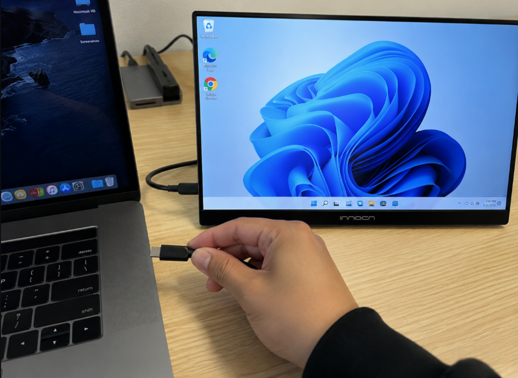
If it works normally when plugged in forward but fails when reversed, common causes include: poor soldering of connector A8/B8, dirty or oxidized contacts, broken SBU on one side of the cable, incorrect MUX control polarity, damaged single-channel ESD protection device, and firmware not correctly switching paths according to direction.
2.5 Electrical Boundaries and Safety Limitations of SBU
SBU is an externally pluggable low-speed auxiliary signal line that does not carry large current itself. Direct connection to VBUS (power pin), high-drive power supplies, or large loads is strictly prohibited. Incorrect connection may directly damage the PD controller, audio Codec, MUX, or even the main chip.
Under different operating modes, the voltage, current, impedance, and bias requirements of SBU are different. Specific parameters shall be subject to the USB Type-C specification, industry standards for the corresponding mode (such as the DP Alt Mode specification), and chip datasheets.
SBU requires ESD electrostatic protection, but you can’t just add any TVS diode: the capacitance, leakage, clamping voltage, and package parasitic parameters of the protection device must be adapted to the application scenario, otherwise it will instead affect signal quality, for example causing DP AUX communication failure or increased audio background noise.
3. Uses of SBU in Different USB-C Modes
The function of SBU is not fixed and depends entirely on the current operating mode of USB-C. Below are the most common scenarios, as well as the specific role and boundaries of SBU in them.
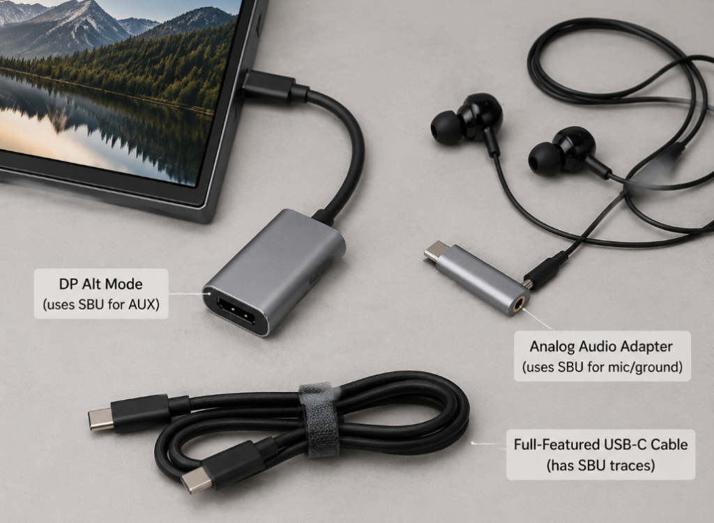
3.1 DP Alt Mode: SBU Carries DisplayPort AUX Auxiliary Link
This is the scenario where ordinary users most commonly encounter SBU, mainly including applications such as USB-C direct connection to monitors, portable screens, projectors, as well as HDMI/DP output from USB-C docking stations, and USB-C to DP/HDMI adapters.
In this mode, the core function of SBU is to carry the DisplayPort AUX auxiliary channel, responsible for auxiliary communication tasks such as reading the monitor’s EDID (display device identity and capability information), monitor identification, link training, parameter configuration, and accessing DPCD (DisplayPort Configuration Data). It is important to note that the main video image data we see goes through the DP Main Link mapped to the USB-C high-speed differential lines, and does not go through SBU at all. SBU is only responsible for low-speed communication of control and configuration types. In addition, hot-plug status and interrupt signals in USB-C DP Alt Mode are usually transmitted through PD/VDM related messages, so you cannot attribute all video control signals to SBU.
Fault boundaries should also be clarified: if the AUX channel is abnormal, it may indeed cause problems such as unrecognized monitor, black screen, repeated disconnection, negotiation failure, and unstable link training; but if low resolution and low refresh rate work, but high resolution or high refresh rate fails, more consideration should be given to reasons such as insufficient high-speed differential line bandwidth, overly long cable, DP version limitations, insufficient docking station chip capability, and poor signal integrity. You cannot directly blame all problems on SBU.
3.2 Analog Audio Accessory Mode: SBU Carries Auxiliary Audio-Related Signals
This mode corresponds to accessories such as passive USB-C analog headphones and USB-C to 3.5mm analog adapters, which is also a scenario where many people easily run into problems.
The prerequisite for analog audio accessories to enter working state is that the Audio Adapter Accessory Mode is triggered by the accessory identification resistors on CC1/CC2, and the device itself must also support this mode. After entering the mode, D+/D- that originally transmit USB 2.0 data are reused as analog left and right channels, while SBU1/SBU2 can be used to transmit auxiliary audio connections such as microphone signals and analog ground — but there is no fixed pinout correspondence here. The specific mapping shall be subject to the Type-C specification, chip reference design, and actual accessory pinout.
For ordinary users, there is a very important boundary: many new mobile phones, tablets, and laptops have now eliminated the analog audio accessory mode and only support digital USB audio. In this case, buying an analog adapter will not work. Even if the device supports it, compatibility issues may occur, such as being able to listen to music but the microphone not working, in-line control failure, high background noise, abnormal left and right channels, and insertion identification failure. Common causes include the device not supporting analog mode, buying the wrong type of adapter, differences in headphone CTIA/OMTP standards, SBU or ground wire compatibility issues, and improper design of the audio Codec or analog switch.
3.3 Digital DAC Audio Adapters: Usually Do Not Rely on SBU
Many people confuse digital DAC adapters with analog adapters, but in fact their working principles are completely different. A digital DAC adapter is essentially an independent USB audio device with a built-in USB controller and DAC (digital-to-analog conversion) chip.
Its signal path is: digital audio data in USB 2.0 format is transmitted through D+/D-, then the DAC chip inside the adapter converts the digital signal into analog audio and outputs it to the headphones. The entire process generally does not require SBU participation, so if there is a problem with a digital DAC adapter, first check the system audio output, USB device identification, driver compatibility, power supply, and adapter quality, without suspecting SBU first.
When purchasing, you can also quickly distinguish by keywords: those marked with “DAC”, “digital decoding”, “USB Audio”, or “built-in sound card” are usually digital models; those marked with “analog”, “no DAC”, or “requires phone to support analog audio” are models that use analog mode and SBU.
3.4 Thunderbolt/USB4: Cannot Be Simply Inferred Using Ordinary SBU Logic
In more complex high-speed modes such as Thunderbolt and USB4, the role of SBU is different from that in ordinary DP Alt Mode. In the Thunderbolt/USB4 environment, there is a set of complex mechanisms such as sideband management, authentication, cable identification, and link management. SBU may participate in specific sideband signal paths, but the specific mapping rules, signal requirements, active cable design, and retimer/redriver design are all constrained by the Thunderbolt/USB4 specifications and corresponding chip solutions, and there is no unified “fixed function”.
For ordinary users, do not judge the Thunderbolt/USB4 capability of a cable or port solely by “whether SBU is connected”. The correct way to judge is to look at the device port identification, cable certification information, official specification parameters, as well as the actually tested speed and video capability. For hardware designers, you cannot directly apply the AUX routing experience of DP Alt Mode to Thunderbolt/USB4. You must design in accordance with the corresponding specifications of the controller, MUX, retimer, connector, and cable.
3.5 Debug and Vendor-Specific Accessory Mode
SBU also has another type of professional scenario use: debugging and vendor-customized accessories, such as Debug Accessory Mode, factory test fixtures, industrial equipment communication, vendor-defined closed ecosystem accessories, and specific maintenance cables, mainly targeting professional objects such as development boards, mass production testing, industrial equipment, and maintenance tools.
In such scenarios, the function of SBU is completely defined by the vendor, but that does not mean it can be used arbitrarily: SBU cannot be used as an ordinary peripheral interface or bare GPIO (general-purpose input/output pin). During design, mode identification rules, voltage range, current limit, ESD protection, plug-in transient impact, and protection measures after incorrectly plugging in ordinary cables must be considered. Vendor-customized SBU usage must be clearly written into the hardware specification, test specification, and maintenance specification to avoid misjudgment during mass production and after-sales stages.
4. Division of Labor Comparison Between SBU and Other USB-C Pins
To help you quickly sort out the responsibilities of each pin, here is a comparison table:
| Pin/Structure | Core Responsibility | Typical Fault Symptoms | Core Difference from SBU |
|---|---|---|---|
| CC pin | Insertion detection, direction identification, PD communication, Alt Mode/accessory mode negotiation | No charging, no accessories recognized, unable to enter expansion mode | CC is the “decision-maker”, responsible for mode entry; SBU is the “executor”, responsible for auxiliary signals within the mode |
| D+/D- | USB 2.0 data transmission, digital DAC audio data link | USB flash drive/mouse/keyboard not working, digital DAC headphones no sound | D+/D- are responsible for general USB data; SBU is only responsible for dedicated auxiliary signals in expansion/accessory modes |
| High-speed differential lines | High-bandwidth data transmission for USB 3.x/USB4/Thunderbolt/DP main link | High-resolution high-refresh failure, slow large file transfer, Thunderbolt speed not up to standard | High-speed differential lines transmit main data (including video images); SBU transmits low-speed auxiliary control signals |
| VBUS/GND | Power supply and current return | No charging, insufficient power supply, device power off | VBUS/GND are power paths; SBU is a signal path and cannot carry current |
| Shielding layer/chassis ground | Electromagnetic interference suppression, chassis grounding, electrostatic discharge | Strong interference, high background noise, failed ESD test; in analog audio scenarios, background noise, howling, or touch noise may occur | The shielding layer is a protective structure, SBU is a functional signal pin, the two cannot replace each other; in analog audio scenarios, the connection between analog ground and shielding layer needs to be planned separately |
5. Key Points of SBU Routing and Engineering Design
This part of the content is mainly for hardware design, testing, and maintenance personnel. Ordinary users can skip it, or can have a brief understanding to help determine whether the problem lies in the design or the accessories.
5.1 First Determine Whether the Product Really Needs SBU
Not all USB-C products need to connect SBU. First determine the requirements based on product functions:
- Charging-only products: usually do not need SBU, but unused pins must be handled according to connector and chip recommendations to avoid long floating traces, incorrect connections, or ESD hazards;
- Products supporting DP Alt Mode: need to plan the complete link from SBU to the PD controller, DP AUX path, MUX, or related pins of the main chip;
- Products supporting analog audio: need to connect D+/D-, SBU, audio ground, microphone, analog switch, and audio Codec in accordance with the Audio Adapter Accessory Mode specification;
- Products supporting debug/dedicated accessories: need to clearly define mode identification rules, electrical range, protection strategy, misplug handling, and mass production testing methods.
5.2 Schematic Design Checklist
Many SBU problems are planted at the schematic stage. When designing, focus on checking these items:
- Confirm that SBU1/SBU2 are connected to the correct chip pins or MUX channels, to avoid mixed connections with CC, D+/D-, high-speed lines, VBUS, or GND;
- Confirm that the Type-C connector package is consistent with the schematic symbol pin positions, with focus on checking A8/B8;
- The reversible insertion direction control signal must come from a reliable CC/PD status output, and cannot be fixed pulled high or low;
- ESD components are placed close to the connector, and the model meets the requirements of low capacitance, low leakage, clamping capability, and signal amplitude;
- Series resistors, common-mode components, and filter components are added according to the chip reference design. It is forbidden to arbitrarily add large capacitors or strong filtering based on experience;
- Unused SBU are not recommended to be routed long distances to pin headers, test sockets, or board edges; necessary test points should be as short as possible, close to the connector, low parasitic, and their purpose should be specified in the mass production specification;
- Retain debug observability: video products can reserve AUX test points or PD log interfaces, and audio products can reserve microphone bias and audio ground test points.
5.3 Core Requirements for PCB Routing
Although SBU is a low-speed signal, poor routing can also cause various problems. Core requirements include:
- Traces should be as short and straight as possible, reducing vias, branches, and stubs;
- Keep away from high-noise areas such as switching power supply inductors, VBUS high-current paths, high-speed clocks, RF antennas, motor drives, and backlight boost circuits;
- Maintain a continuous reference ground plane, avoid crossing split grounds or power gaps, and reduce noise coupling caused by cut return paths;
- Maintain a reasonable distance from high-speed differential lines to reduce crosstalk; SBU does not need to strictly control differential impedance like USB 3.x high-speed lines, but cannot be routed arbitrarily;
- For DP AUX use: focus on ESD capacitance, trace parasitics, and AUX communication stability;
- For analog audio use: focus on analog ground planning, noise coupling, microphone bias, shielding, and left-right channel crosstalk.
5.4 Key Points of ESD and Protection Design
SBU is an externally pluggable pin, so protection design must balance protection effect and signal quality:
- Need to cover protection against electrostatic discharge, surge, hot-plug transients, and misplug risks;
- TVS/ESD components should be placed as close to the USB-C connector as possible, so that static electricity is discharged before entering the board;
- Select components with low capacitance, low leakage, and adapted working voltage and clamping voltage;
- It is forbidden to use protection components with excessive capacitance, to avoid causing degraded DP AUX edges, communication failure, or degraded analog audio high-frequency response and noise performance;
- Coordinate the system ESD path: the connection strategy between the chassis, shielding layer, board ground, and connector shell must not be confused with SBU functions.
5.5 Precautions for Reversible Insertion MUX Switching Design
Reversible insertion switching is a common pitfall in SBU design. Pay attention to these issues:
- The SBU path must be switched according to the direction detection result of CC1/CC2, and cannot be hardwired;
- When selecting Type-C port controllers, PD controllers, Alt Mode MUX, and analog switches, confirm that the SBU channel’s bandwidth, on-resistance, leakage, capacitance, default state, power-off state, and control polarity all meet the requirements. Don’t only look at high-speed channel parameters;
- Common design errors: SBU1/SBU2 reversed, misunderstanding of MUX input/output direction, reversed control polarity, firmware not opening the SBU channel after entering Alt Mode, MUX turning off in low-power/sleep state causing display abnormalities after wake-up;
- Verification should cover all scenarios: forward insertion, reverse insertion, hot plug, sleep wake-up, low battery, different cables, and different monitors/accessories.
5.6 Engineering Debugging and Verification Methods
Debugging SBU-related problems should be done in order, don’t test randomly:
- Basic continuity check: Confirm that the continuity from SBU to the target chip or MUX is normal, and there is no short circuit to VBUS, GND, CC, D+/D-, or high-speed lines;
- Mode entry check: Confirm that CC direction detection is correct, the PD controller has completed relevant negotiations, and successfully sent and received mode-related messages such as Enter Mode and Configure — many times it is not an SBU problem at all, but the mode was not entered;
- MUX status check: Confirm that the firmware switches the SBU and high-speed line paths at the correct time, and can recover normally after low power, reset, or abnormal plugging/unplugging;
- DP scenario check: Capture PD logs to confirm DP Alt Mode entry, check AUX EDID reading, DPCD access, link training success rate, and HPD/Attention events during black screen;
- Audio scenario check: Confirm whether analog audio accessory mode is entered, test left and right channels, microphone bias, background noise, crosstalk, and in-line control compatibility;
- Mass production test requirements: Cover forward/reverse insertion, different cables, and different accessories; video products test multiple resolution/refresh rate combinations; audio products test channels, microphone, in-line control, and background noise; products without SBU test for no misconnection or short circuit.
6. User Purchasing and Accessory Judgment: When to Pay Attention to SBU
For ordinary users, there is no need to delve into the electrical parameters of SBU, but you need to know when to consider SBU-related compatibility to avoid buying the wrong accessories.
6.1 Scenarios Where SBU Must Be Considered
- USB-C direct connection to monitors, portable screens, projectors;
- HDMI, DP, VGA video output from USB-C docking stations;
- Passive USB-C analog headphones or USB-C to 3.5mm analog adapters;
- Vendor-specific debug cables, industrial accessories, factory test accessories.
6.2 Scenarios Where SBU Usually Does Not Need to Be Considered
- Charging only, no screen mirroring, no analog audio connection, no use of dedicated accessories;
- Basic peripherals such as ordinary USB 2.0 mice, keyboards, USB flash drives, and card readers;
- Digital DAC audio adapters, because they use USB digital audio data;
- For file transfer between ordinary mobile phones and computers, usually just pay attention to the USB data cable specifications.
6.3 Accessory Purchasing Keywords
You don’t need to disassemble the accessory to look at the pins, you can roughly judge the direction through keywords, but note that keywords are for reference only:
- Video accessories: Products marked with “DisplayPort Alt Mode”, “DP Alt Mode”, “supports video output”, “full-featured USB-C”, “4K60”, “8K30”, “Thunderbolt”, “USB4” can be used as initial screening directions, but whether related functions are ultimately supported still depends on the device port specifications, officially marked video output capability, target resolution and refresh rate, and certification information. Compatibility cannot be directly judged solely by keywords;
- Cables: Full-featured USB-C cables, video cables, Thunderbolt 3/4/5 cables, and USB4 cables usually have complete SBU and high-speed differential line routing, but the actual supported capabilities still need to be subject to official specifications and certification information; most pure charging cables and low-cost USB 2.0 cables do not have SBU connected and usually do not support video output;
- Audio adapters: For digital models, look for “DAC”, “USB Audio”, “digital decoding”, “built-in sound card”; for analog models, look for “analog audio”, “Audio Accessory Mode”, “requires device to support analog headphones”;
- Pitfall reminder: Only marking “100W fast charge” or “fast charge cable” does not mean it supports video; only marking “Type-C headphone adapter” also cannot tell whether it is a digital DAC or analog model, be sure to read the specific instructions on the detail page.
6.4 Clarification of Common Misconceptions
- Misconception: SBU is a useless unused pin
Correction: It is not used for ordinary charging/USB data, but it is used for video, analog audio, and debug accessories, so it is not an unused pin. - Misconception: Having a USB-C port means it must support SBU-related functions
Correction: The physical port having contacts does not mean that internal routing, chips, firmware, and protocols are all supported. The SBU of many low-cost charging ports is not connected at all. - Misconception: Being able to charge means SBU is normal
Correction: Charging mainly relies on VBUS/GND/CC. SBU damage may still allow normal charging. - Misconception: Being able to transfer files means you can mirror the screen
Correction: File transfer uses the ordinary USB data link, while screen mirroring requires DP Alt Mode, high-speed differential lines, and the SBU AUX channel, which are completely different link requirements. - Misconception: Reversible insertion must have no difference at all
Correction: The design goal is no difference, but problems with connectors, cables, MUX, ESD, or soldering can cause single-direction failures. - Misconception: All USB-C to 3.5mm adapters are the same
Correction: Digital DAC models and analog passive models have different working principles and different compatibility conditions. Buying the wrong one will not work at all.
7. SBU-Related Troubleshooting Ideas
When encountering problems, don’t suspect SBU right away. First triage, then troubleshoot by scenario, which is more efficient.
7.1 First Triage: Don’t Blame SBU First
- No charging at all, no accessories recognized: first check VBUS, GND, CC, device power supply, and port damage, which have nothing to do with SBU;
- Charging works but screen mirroring doesn’t: first confirm whether the device, cable, docking station, and monitor support DP Alt Mode or the corresponding video mode, then troubleshoot the SBU and high-speed link;
- File transfer works but screen mirroring doesn’t: this only means that D+/D- or USB data function may be normal, and cannot prove that SBU, high-speed DP link, or Alt Mode negotiation is normal;
- Analog headphones have no sound: first distinguish whether the adapter is an analog model or a digital DAC model, then confirm whether the device supports the corresponding mode.
7.2 Troubleshooting Steps for Charging Working But Screen Mirroring Not Working
- Confirm whether the USB-C port of the computer/phone/tablet supports DP Alt Mode, Thunderbolt, USB4, or the officially marked video output function;
- Confirm that the monitor, docking station, and adapter support the corresponding input mode and target resolution/refresh rate;
- Replace with a known qualified full-featured USB-C cable or certified Thunderbolt/USB4 cable to rule out problems with pure charging cables, USB 2.0 cables, and inferior cables;
- Test once with forward insertion and once with reverse insertion to determine if it is a single-direction fault;
- Test with reduced resolution/refresh rate; if low specifications work and high specifications fail, it is more likely a problem with high-speed link bandwidth or signal integrity, don’t only attribute it to SBU.
Engineering side supplement: Capture PD logs to confirm whether DP Alt Mode is entered, check Configure VDM, HPD/Attention events, AUX EDID reading, and link training status.
7.3 Troubleshooting Slow Monitor Recognition, Black Screen, and Intermittent Disconnection
Possible SBU-related causes: Unstable DP AUX, poor contact, ESD damage, abnormal MUX switching, A8/B8 soldering problems.
Possible causes unrelated to SBU: Poor quality high-speed differential lines, overly long cable, overheating docking station chip, insufficient power supply, monitor firmware compatibility, system graphics driver problems.
User-side troubleshooting sequence: Replace with short cable → Replace with good full-featured cable → Replace monitor/docking station → Update system and docking station firmware → Clean dust and foreign objects from the port.
Engineering-side troubleshooting sequence: Check CC direction → Check PD negotiation → Check MUX status → Check AUX waveform/communication → Check high-speed link eye diagram or bit error rate → Check hot plug and sleep wake-up.
7.4 Troubleshooting USB-C to 3.5mm No Sound or Microphone Not Working
- Step 1: Confirm whether the adapter is an analog passive model or a digital DAC model;
- For analog models, you must confirm that the device supports Audio Adapter Accessory Mode. If not, replace with a digital DAC model;
- When a digital DAC model has no sound, check USB device identification, audio output selection, system permissions, driver compatibility, and adapter power supply;
- If you can listen to music but the microphone doesn’t work, focus on troubleshooting SBU-related microphone/analog ground compatibility, adapter pinout, and headphone CTIA/OMTP standard differences;
- For high background noise or static, troubleshoot analog ground, shielding, cable quality, device audio design, and ground noise caused by using while charging.
7.5 Troubleshooting Forward Insertion Normal, Reverse Insertion Failure
Common user-side causes: Dirty or worn contacts on one side of the cable, dirty port, internal routing problems of the adapter, loose connector.
Common engineering-side causes: Incorrect CC direction judgment, SBU MUX control error, poor soldering of connector A8/B8, single-channel ESD damage, abnormal firmware state machine.
Troubleshooting methods: Clean the port → Replace cable → Replace device → Replace docking station/adapter; the engineering side uses continuity testing, oscilloscopes, PD protocol analyzers, and AUX communication logs for localization.
8. Quick Summary: Judgment Abilities to Master After Learning
8.1 Remember SBU in One Sentence
SBU are two auxiliary signal lines in USB-C used for expansion modes and accessory modes, most commonly found in DP video auxiliary links, analog audio accessories, and debug or vendor-specific accessories.
8.2 Three Core Judgment Abilities
- Function judgment: Ordinary charging and basic USB data usually do not require SBU; video output, analog audio, and dedicated accessories are more likely to require SBU.
- Accessory judgment: Full-featured cables, video cables, and Thunderbolt/USB4 cables usually have SBU-related routing, but actual capabilities are subject to official specifications; most pure charging cables and low-cost USB 2.0 cables do not support SBU-related functions.
- Fault judgment: When charging works but video/analog audio is abnormal, you should troubleshoot device capabilities, cables, Alt Mode negotiation, MUX, SBU, and high-speed link together in layers, don’t blame SBU right away.
8.3 The Most Important Boundary Awareness
SBU is not the cause of all faults: video abnormalities are not necessarily SBU problems, high-refresh failures are often related to the high-speed link; audio silence may also be due to adapter type or device not supporting it.
But SBU also cannot be ignored: as long as the product involves DP Alt Mode, analog audio accessories, debug accessories, or vendor-specific accessories, the definition, routing, protection, and reversible insertion switching of SBU must be carefully designed, otherwise various indescribable small problems will occur.