
USB 2.0 is one of the most important interface standards in the history of personal computers and consumer electronics. It dramatically improved the performance of earlier USB versions while keeping the same plug-and-play experience that made USB popular in the first place.
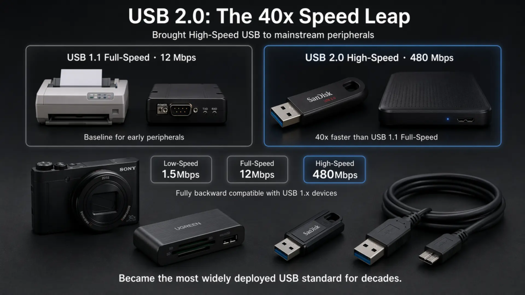
Released in 2000 by the USB Implementers Forum, USB 2.0 introduced High-Speed operation at 480 Mbps. Compared with USB 1.1 Full-Speed at 12 Mbps, this was a 40x increase in nominal signaling rate. That single improvement made USB practical for flash drives, external storage, cameras, card readers, scanners, printers, and many other peripherals.
Even though USB 3.x and USB4 have replaced USB 2.0 in many high-performance scenarios, USB 2.0 remains widely used because it is mature, inexpensive, power-efficient, and compatible with a huge range of devices.
1. Overview and Historical Background
USB 2.0 was created to solve a clear limitation of USB 1.1: bandwidth. USB 1.1 worked well for keyboards, mice, printers, and simple peripherals, but its 12 Mbps Full-Speed mode was not enough for growing storage, imaging, and multimedia needs.
The main upgrade in USB 2.0 was the addition of High-Speed mode at 480 Mbps. At the same time, USB 2.0 preserved support for the older Low-Speed and Full-Speed modes, which allowed existing USB 1.x devices to continue working on newer systems.
1.1 Core Features
- High-Speed data transfer up to 480 Mbps
- Backward compatibility with USB 1.x Low-Speed and Full-Speed devices
- Hot plugging and plug-and-play device detection
- Host-controlled communication model
- Differential signaling over D+ and D- lines
- Support for hubs and tree-style topology expansion
- Support for bus-powered and self-powered devices
USB 2.0 quickly replaced USB 1.1 as the mainstream peripheral interface and became widely adopted across PCs, consumer electronics, embedded systems, industrial peripherals, and development boards.
2. Technical Specifications
USB 2.0 supports three speed modes: Low-Speed, Full-Speed, and High-Speed. The device and host negotiate the operating speed when a device is attached.
| Speed Mode | Nominal Signaling Rate | Typical Devices |
|---|---|---|
| Low-Speed | 1.5 Mbps | Keyboard, mouse, simple HID devices |
| Full-Speed | 12 Mbps | Printers, scanners, audio devices, legacy peripherals |
| High-Speed | 480 Mbps | USB flash drives, card readers, cameras, external storage |
The 480 Mbps value is the nominal signaling rate, not the actual application-level data throughput. Real throughput is lower because of protocol overhead, host scheduling, device implementation, transfer type, software stack, and storage performance.
2.1 Electrical Characteristics
USB 2.0 uses a 5V VBUS power line and a differential data pair, D+ and D-. Data is transmitted through differential signaling, which improves noise immunity compared with single-ended signaling.
A USB 2.0 device may be bus-powered or self-powered. A bus-powered device draws power from the host or hub through VBUS. A self-powered device uses its own external power supply and does not rely entirely on USB bus power.
For a standard USB 2.0 downstream port, a configured device can typically draw up to 500mA at 5V, which equals about 2.5W. Before configuration, the device must follow lower current limits until the host allows its configured power level.
2.2 Cable Length
| Speed Mode | Typical Maximum Cable Length |
|---|---|
| Low-Speed | 3 meters |
| Full-Speed | 5 meters |
| High-Speed | 5 meters |
USB cable length is limited by signal integrity, propagation delay, and timing requirements. Longer distances normally require hubs, repeaters, active cables, or a different communication technology.
3. Physical Layer and Connectors
USB 2.0 preserved the basic four-wire structure of earlier USB versions while supporting higher-speed signaling.
| Pin / Wire | Function |
|---|---|
| VBUS | 5V power supply |
| D+ | USB differential data signal |
| D- | USB differential data signal |
| GND | Ground reference |
3.1 Connector Types
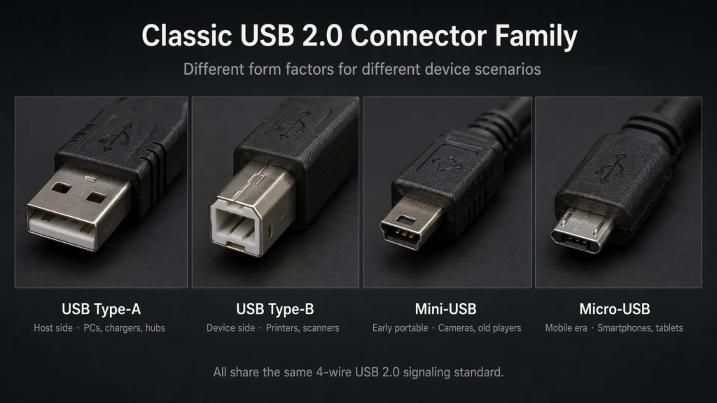
Classic USB 2.0 connector types include:
- USB Type-A: Commonly used on the host side, such as PCs and chargers.
- USB Type-B: Commonly used on larger peripherals such as printers and scanners.
- Mini-USB: Used on older mobile devices, cameras, and portable electronics.
- Micro-USB: Widely used on smartphones, tablets, accessories, and embedded devices before USB Type-C became common.
- Micro-AB: Used in USB OTG scenarios to support role detection.
USB OTG connectors include an additional ID pin. This pin helps determine which device should initially act as the host and which should act as the peripheral.
3.2 Signal Encoding
USB 2.0 uses NRZI encoding together with bit stuffing. NRZI encoding represents data through signal transitions and non-transitions, while bit stuffing prevents long runs without transitions.
This helps the receiver maintain synchronization and recover timing information from the incoming signal. Combined with differential signaling, this allows USB 2.0 to maintain reliable communication over short peripheral cables.
4. Protocol Layer and Data Transfer
USB 2.0 uses a host-centric architecture. The host controls the bus, schedules transfers, sends tokens, manages device addresses, and decides when each device may communicate.
Devices do not freely transmit whenever they want. They respond to host requests. This is a key difference between USB and peer-to-peer network technologies.
4.1 Host, Device, and Hub Roles
A USB 2.0 system contains three major roles:
| Role | Function |
|---|---|
| Host | Controls the bus, schedules transfers, enumerates devices, and loads drivers |
| Device | Provides a function, such as storage, input, audio, imaging, or communication |
| Hub | Expands one upstream port into multiple downstream ports and manages connection events |
USB uses a tiered star topology. The root hub is integrated into the host, and external hubs can extend the topology. A USB bus can support up to 127 device addresses, including hubs.
4.2 Transfer Types
USB 2.0 defines four major transfer types. Each type is designed for a different balance of reliability, bandwidth, and latency.
| Transfer Type | Main Purpose | Typical Use |
|---|---|---|
| Control Transfer | Configuration, enumeration, standard requests | All USB devices |
| Interrupt Transfer | Small data with predictable latency | Keyboard, mouse, game controller, HID device |
| Bulk Transfer | Reliable large data transfer without guaranteed latency | Flash drive, printer, scanner, storage device |
| Isochronous Transfer | Real-time data with reserved bandwidth and no retry | Audio, video, streaming device |
Control and interrupt transfers are available across USB speed modes. Bulk and isochronous transfers are used for Full-Speed and High-Speed devices, not Low-Speed devices.
4.3 Transactions, Frames, and Microframes
USB 2.0 communication is organized into transactions. A typical transaction may include a token packet, a data packet, and a handshake packet.
- Token packet: Sent by the host to identify the target device, endpoint, and direction.
- Data packet: Carries payload data.
- Handshake packet: Reports success, retry, or error status when applicable.
For Low-Speed and Full-Speed communication, USB uses 1 ms frames. For High-Speed communication, each 1 ms frame is divided into eight 125 μs microframes. This microframe structure allows the host to schedule high-speed traffic more efficiently.
5. Power Management
USB 2.0 includes basic but important power management features. These features allow the host to control power usage, support suspended devices, and protect the system from over-current conditions.
5.1 Bus-Powered and Self-Powered Devices
A bus-powered device takes power from the USB VBUS line. This is common for keyboards, mice, flash drives, card readers, adapters, and small accessories.
A self-powered device has its own power supply. Examples include many printers, scanners, external hard drive enclosures, and powered hubs. These devices may still use USB for data communication while drawing most operating power from an external adapter.
5.2 Suspend and Remote Wakeup
USB devices can enter a low-power suspend state when the bus is idle. This reduces power consumption, especially for portable systems.
Some devices also support remote wakeup. For example, a keyboard or mouse may wake a suspended computer when the user presses a key or moves the mouse, if the host and operating system allow that behavior.
5.3 Over-Current Protection
USB hosts and hubs typically include over-current detection and protection. If a downstream port draws too much current or a short circuit occurs, the host or hub can disable the affected port to protect the system.
This protection is especially important because USB allows hot plugging and bus-powered devices.
6. Topology and Expansion
USB 2.0 uses a tree-like topology that begins at the host root hub. External hubs extend the number of available ports and allow multiple devices to share one host controller.
The USB topology supports up to 127 device addresses. The tier depth is limited by the USB specification, so hubs cannot be cascaded indefinitely. In practical terms, only a limited number of hubs can exist between the host and the final device.
6.1 Hub Functions
A USB 2.0 hub is not just a passive splitter. It performs several important functions:
- Detects device connection and removal
- Reports port status changes to the host
- Manages downstream port power
- Repeats and reshapes signals
- Supports Low-Speed, Full-Speed, and High-Speed device operation
- Handles transaction translation when needed for mixed-speed USB 2.0 topologies
In High-Speed USB 2.0 systems, hubs may include transaction translators to help Low-Speed and Full-Speed devices work correctly behind a High-Speed hub.
6.2 USB OTG
USB On-The-Go, or OTG, was introduced to allow certain devices to act as either host or peripheral depending on the connection scenario. This was useful for products such as cameras, phones, and portable media devices.
OTG uses role negotiation and, in older Micro-USB implementations, the ID pin to determine the initial host/peripheral relationship. However, even in OTG mode, USB communication still follows the host-device model. It is not a general-purpose peer-to-peer network.
7. Common Applications
USB 2.0 became the default interface for a wide range of devices because it offered enough bandwidth for many peripherals while keeping implementation cost low.
| Device Category | Typical Speed Mode | Examples |
|---|---|---|
| Low-bandwidth HID | Low-Speed or Full-Speed | Keyboard, mouse, game controller |
| General peripherals | Full-Speed | Printer, scanner, older audio device |
| Storage and imaging | High-Speed | USB flash drive, card reader, camera, external drive |
| Embedded and industrial devices | Full-Speed or High-Speed | Debug adapters, data acquisition devices, control modules |
USB 2.0 remains common in embedded systems because it is inexpensive, well-supported by operating systems, and sufficient for many control, diagnostic, and moderate-bandwidth applications.
8. Compatibility with USB 1.x and USB 3.x
USB 2.0 is backward compatible with USB 1.x devices. A USB 1.1 keyboard, mouse, or printer can usually operate on a USB 2.0 host at its original Low-Speed or Full-Speed rate.
USB 2.0 devices can also be connected to USB 3.x ports. In that case, the device still operates as a USB 2.0 device and does not gain USB 3.x SuperSpeed performance. The connector may be newer, but the device’s internal capability determines the actual operating mode.
This compatibility is one reason USB has remained successful for so long. Newer hosts can continue supporting older devices while adding faster modes for newer peripherals.
9. Advantages and Limitations
9.1 Advantages
- Mature and widely supported technology
- Low implementation cost
- Plug-and-play user experience
- Backward compatibility with USB 1.x devices
- Good enough bandwidth for many peripherals
- Simple four-wire cable structure
- Broad operating system and driver support
9.2 Limitations
- 480 Mbps signaling rate is not enough for modern high-speed storage or high-resolution video capture
- Actual throughput is much lower than the nominal signaling rate
- Half-duplex data communication over D+ and D- limits simultaneous bidirectional transfer
- Cable length is limited without hubs or active extension
- Standard bus power is limited compared with USB Power Delivery
- High-bandwidth devices are better served by USB 3.x, USB4, Thunderbolt, or other faster interfaces
Summary
USB 2.0 was a major turning point for USB. By adding High-Speed operation at 480 Mbps while preserving compatibility with Low-Speed and Full-Speed devices, it became the dominant interface for mainstream peripherals for many years.
Its success came from a combination of practical features: hot plugging, plug-and-play enumeration, low cost, bus power, hub expansion, broad operating system support, and enough bandwidth for common devices.
Today, USB 2.0 is no longer the best choice for high-speed storage, modern video capture, or advanced docking. However, it remains extremely important in keyboards, mice, embedded systems, debug interfaces, microcontrollers, adapters, low-cost accessories, and countless devices where reliability, compatibility, and cost matter more than maximum speed.