
1. Introduction: The Invisible Power Controller in Every Electronic Device
The “Hidden Power Steward” Inside Electronics
From phone chargers and laptops to TVs, routers, and even electric vehicles, every modern electronic device relies on a switching power supply system to convert electricity. At the heart of this system is the PWM control chip — the “commanding brain” that stays hidden inside devices but dictates how stably, efficiently, and safely power is delivered. It is the unsung hero that keeps all our electronics running properly.
The Evolution From Linear Regulation to Switching Power Supplies
Early electronics used linear regulators to control voltage. These worked like resistive step-down devices, wasting most excess energy as heat. They were simple but very inefficient, causing devices to run hot and making compact designs impossible.
As demand grew for smaller, cooler, and more powerful electronics, switching power supply technology became the industry standard. It transfers energy through high-speed switching to dramatically improve efficiency, and Pulse Width Modulation (PWM) is the core control method behind it.
What Is a PWM Control Chip and Why It Matters
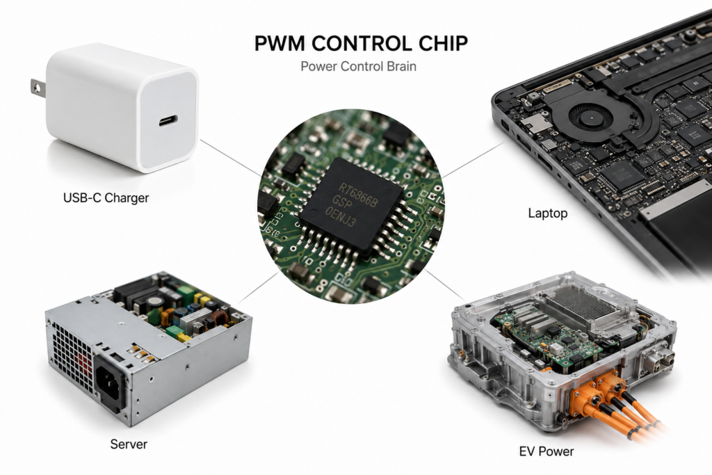
PWM stands for Pulse Width Modulation. In simple terms, it controls the amount of delivered energy by adjusting how long an electrical signal stays on during each on-off cycle. A PWM control chip is an integrated circuit dedicated to this function. It constantly monitors the power supply’s output and automatically adjusts the switching rhythm to keep voltage stable, while balancing efficiency and safety protection.
2. Basic Working Principles
PWM Fundamentals: Frequency, Duty Cycle and Energy Control
Think of PWM control like a kitchen faucet that you turn on and off rapidly. If the total time stays the same, the longer the faucet stays open each cycle, the more water flows out.
- Frequency: How many on-off cycles happen per second. Higher frequency means more adjustments per second and smoother output.
- Duty Cycle: The percentage of time the signal is “on” in one cycle. A higher duty cycle delivers more energy and produces a higher output voltage. PWM technology precisely adjusts the duty cycle to control the output voltage and power of a power supply.
The Full Power Conversion Process
First, the PWM control chip generates a control signal to drive power switches on and off at high speed. Energy passes through energy-storage components like inductors and transformers, then is smoothed by capacitors into steady direct current (DC) for the device. The whole process works like a smart water pump: it “pumps” energy to the output through high-frequency switching, then filters it into a steady flow.
Closed-Loop Feedback: The Key to Stable Output
Stable power relies on closed-loop feedback — the same principle as a home thermostat. The thermostat checks room temperature, compares it to your set point, and turns heating on or off accordingly.
A PWM control chip constantly samples the output voltage and compares it to an internal reference voltage. If the output is too low, it increases the duty cycle to deliver more energy; if the output is too high, it reduces the duty cycle. This real-time adjustment keeps the output voltage stable at all times.
Core Internal Modules
Inside a PWM control chip is a miniature system with specialized modules:
- Reference voltage module: Provides a precise “standard ruler” as the baseline for voltage regulation.
- Error amplifier: Compares the actual output to the reference and calculates the difference.
- Oscillator: Generates a fixed-frequency clock signal, the “heartbeat” of the chip.
- Gate driver module: Amplifies the control signal to drive external power switches.
- Protection circuit module: Monitors for abnormal conditions and shuts down the system in case of danger.
3. Main Control Modes and Their Characteristics
Voltage Mode Control
Voltage mode control is the classic approach. It adjusts the duty cycle based only on output voltage feedback. With a simple structure and good stability, it is like adjusting a water valve based only on water level. It works well for basic power supplies that do not require fast response.
Current Mode Control (Peak / Average)
Current mode control adds real-time current detection on top of voltage feedback. It monitors both voltage and current — like watching both water level and flow speed — so it detects anomalies faster, responds more dynamically, and makes overcurrent protection easier to implement.
- Peak current mode detects the maximum current in each cycle, offering the fastest response and widest use.
- Average current mode detects the average current over a cycle, delivering higher precision for applications that demand accurate current control.
Differences and Use Cases
Voltage mode control has a simple structure and is easy to design, making it suitable for low-power, basic power supplies. Current mode control offers faster response, better stability, and more sensitive protection, making it the mainstream choice for fast chargers, industrial power supplies and other high-performance products.
4. Chip Categories and Product Comparisons
By Power Supply Topology
AC-DC Types: Flyback, Forward, LLC Resonant
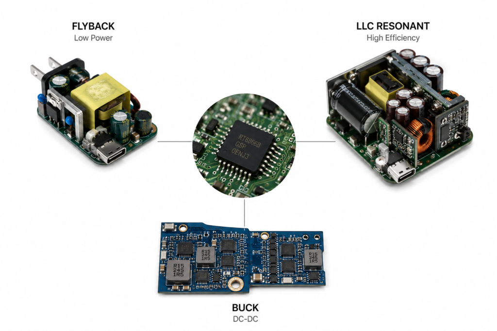
AC-DC power supplies convert household alternating current (AC) to direct current (DC). They are the most familiar type, found in phone chargers and TV power adapters.
- Flyback topology: Simple and low-cost, the most common solution for basic phone chargers and low-power adapters.
- Forward topology: Higher efficiency, ideal for medium-to-high power industrial power supplies.
- LLC resonant topology: Achieves extremely low switching loss and the highest efficiency, and is the core architecture of premium GaN fast chargers and high-power PC power supplies.
DC-DC Types: Buck, Boost, Buck-Boost
DC-DC power supplies convert one DC voltage to another — for example, stepping down a motherboard’s 12V to the 1V needed by a CPU, or stepping up power bank battery voltage to charge a phone. The three main types are Buck (step-down), Boost (step-up) and Buck-Boost (step-up/step-down), for different voltage conversion needs.
By Integration Level
Standalone PWM Controllers
These chips only output control signals; the power switches are placed externally on the circuit board. They offer high flexibility and are suitable for high-power, custom power supply designs.
Integrated Power Switch Chips
These integrate both the PWM control circuit and power switches into a single chip. They require fewer external components, simplify design and reduce size, and are widely used in low-to-medium power consumer electronics.
Highly Integrated System-Level Solutions
These have the highest integration level. They include control, power switches, protocol support and full protection features, with very few external parts needed. They enable extremely compact power supplies, such as mini GaN chargers.
PWM Control Chips vs. LDO Linear Regulators
People often confuse PWM switching power supplies with LDO (Low-Dropout) linear regulators. The key differences are:
| Comparison | PWM Control Chip (Switching Power Supply) | LDO Linear Regulator |
|---|---|---|
| Working principle | Transfers energy via high-speed switching | Dissipates excess energy through resistive drop |
| Efficiency | High, typically 80%–95% | Low, can drop below 50% with large voltage differences |
| Heat generation | Low heat output | Runs hot when voltage difference is large |
| Size | More components but can be miniaturized via high frequency | Simple structure but low power density |
| Typical use | High-power, high-efficiency, wide-voltage scenarios | Low-power, low-noise, small voltage-drop scenarios |
Analog vs. Digital PWM
Traditional analog PWM chips rely entirely on analog circuits for control. They offer fast response and low cost, and remain the mainstream today. Digital PWM chips include an on-board digital core — like a tiny processor — so parameters can be configured via software for smarter control and richer features. They represent a major future trend.
5. Key Performance Parameters and Safety Protection
Core Electrical Parameters
- Operating voltage range: The voltage range in which the chip functions normally.
- Switching frequency: How many times the chip switches per second. Higher frequency allows smaller inductors and capacitors.
- Duty cycle range: The adjustable range of on-time, which determines the voltage conversion range.
Efficiency and Dynamic Performance
- Conversion efficiency: The ratio of output power to input power. Higher efficiency means less wasted energy and less heat.
- Load regulation: How much the output voltage fluctuates as load current changes. Smaller fluctuation means better stability.
- Dynamic response speed: How quickly voltage returns to normal after a sudden load change. Faster response keeps devices running smoothly.
Built-In Safety Protection
Reliable PWM control chips include comprehensive protection features, acting as multiple safety locks for the power supply:
- Overcurrent Protection (OCP): Limits or shuts down output when current exceeds safe levels, preventing damage to the chip and devices.
- Overvoltage Protection (OVP): Shuts down quickly if output voltage rises abnormally, protecting connected electronics.
- Undervoltage Lockout (UVLO): Stops operation when input voltage is too low, preventing abnormal chip behavior.
- Over-Temperature Protection (OTP): Reduces power or shuts down when the chip gets too hot, preventing thermal damage.
- Short-Circuit Protection (SCP): Immediately cuts output during a short circuit to avoid burning out the circuit.
6. Major Manufacturers and Representative Products
Leading International Manufacturers
- Texas Instruments (TI): Offers a full product lineup from consumer to industrial-grade power supplies, known for performance and reliability.
- onsemi: Widely used in fast chargers and LED drivers, with strong cost-performance.
- Power Integrations (PI): Specializes in highly integrated flyback controllers, a leading supplier for phone chargers and fast charging adapters.
- Infineon: Strong in industrial power and automotive electronics, with exceptional reliability.
Key Domestic Manufacturers
Domestic Chinese manufacturers have advanced rapidly in recent years, gaining growing market share in consumer electronics and LED lighting. Leading players include Silergy, SG Micro, Chipown and Bright Power Semiconductor, offering cost-effective products tailored to consumer electronics needs.
7. Common Real-World Applications
USB-C Fast Chargers and Consumer Adapters
Every phone charger, USB-C PD fast charger and laptop power adapter relies on a PWM control chip at its core. From basic 5W chargers to 240W high-power fast charging, PWM chips deliver precise power control for efficient, safe charging.
PCs, Servers and Industrial Power Supplies
Desktop PC ATX power supplies, server power units and industrial equipment power all depend on PWM control chips for stable multi-voltage output. These applications demand extremely high stability and reliability, and the PWM chip directly determines operational safety.
LED Lighting and Motor Speed Control
LED brightness adjustment and brushless motor speed control both rely on PWM technology. By adjusting the duty cycle, users can precisely control LED brightness and motor speed with high efficiency and accuracy.
New Energy and Energy Storage
PWM control chips are core components in photovoltaic inverters, energy storage power supplies and electric vehicle on-board power systems. They handle efficient energy conversion and management, making them indispensable in new energy systems.
The table below maps common scenarios to their typical power solutions:
| Application | Common Topology | Typical Chip Type |
|---|---|---|
| Basic phone charger | Flyback AC-DC | Integrated flyback PWM controller |
| High-power GaN fast charger | LLC resonant AC-DC | High-performance resonant PWM controller |
| PC motherboard CPU power | Step-down DC-DC (Buck) | Multi-phase PWM controller |
| LED ceiling light driver | Buck / flyback | Constant-current PWM control chip |
| Electric vehicle motor drive | Three-phase inverter | Motor-specific PWM controller |
8. Selection Guide and Basic Design Tips
Core Selection Principles
You do not need the most advanced model — the best chip is the one that matches your needs. First determine whether you need an AC-DC or DC-DC solution, then define your power level. Finally, choose a control mode and integration level based on your requirements for efficiency, size and cost.
Peripheral Circuit and PCB Design Basics
PWM chips operate at high switching frequencies, so peripheral circuits and PCB layout strongly affect performance. Key rules include: keep power loop traces short and thick to reduce loss and interference; separate signal ground and power ground to prevent high-frequency noise from disrupting control signals; place input and output capacitors close to chip pins for stable power delivery.
Common Design Mistakes to Avoid
- Higher frequency is not always better: Higher frequency increases switching loss and electromagnetic interference. A balance between size and efficiency is necessary.
- More power margin is not always better: Excessive margin raises cost and can reduce light-load efficiency.
- Never skip protection features: Proper designs must use the chip’s built-in protection to prevent damage during abnormal conditions.
9. Technology Trends
Higher Frequencies: Matching Wide-Bandgap Semiconductors for Greater Power Density
With the spread of wide-bandgap devices like Gallium Nitride (GaN) and Silicon Carbide (SiC), PWM control chips are moving toward higher switching frequencies. Higher frequency drastically reduces the size of transformers and inductors, enabling smaller and lighter power supplies — the main reason mini fast chargers have become so popular.
Digital and Intelligent Control
Digital PWM chips are developing rapidly. They allow flexible software configuration, adaptive efficiency optimization, dynamic load adjustment and other smart features. They also support bus communication for intelligent power management. Power supplies will become much “smarter” in the future.
Higher Integration and Miniaturization
Chip integration keeps improving: from standalone controllers to integrated power switches, then to fully integrated protocol and protection features. Fewer external components are needed, products get smaller, and design becomes simpler.
Lower Standby Power and Greener Energy Efficiency
As global demand for energy efficiency grows, PWM control chips continue to improve light-load and standby power consumption. Technologies like burst mode and frequency reduction keep power draw very low during idle or light-load conditions, meeting global green energy standards.
10. Summary and Outlook
Though often overlooked, PWM control chips are the “core brain” of every electronic power system. They determine efficiency, stability, safety and size, and power countless devices from consumer electronics to industrial equipment and new energy systems.
As semiconductor technology advances, PWM control chips will continue to evolve toward higher frequency, greater intelligence, higher integration and better energy efficiency, bringing us smaller, faster and more power-efficient electronic devices.