
Everyone loves USB-C’s “plug it in either way” convenience. No more flipping the connector over several times before it fits.
But this isn’t just because the connector looks symmetrical. USB-C’s reversible design is the result of four layers working together: the mechanical structure, contact layout, electrical detection, and internal signal routing.
Think of USB-C like a double-sided key and the device like a smart lock. The key works either way because the lock can instantly recognize its orientation and automatically connect the correct internal circuits. The whole process happens so quickly that you never notice it.
1. The Big Picture: How USB-C Reversible Plug Works
USB-C achieves reversible insertion through four layers that work together:
- Physical layer – A rotationally symmetric connector provides the mechanical foundation.
- Detection layer – CC (Configuration Channel) pins determine the plug orientation.
- Switching layer – Internal circuits automatically route high-speed signals to the correct paths.
- Function layer – Charging, data transfer, video output and other advanced features work normally regardless of plug orientation.
In simple terms:
Build a connector that works in either orientation → Detect which side is inserted → Automatically connect the correct internal circuits.
2. Physical Layer: The Symmetric Hardware Foundation
2.1 Twenty-Four Contacts with 180° Rotational Symmetry
A USB-C receptacle (the port on your device) contains 24 electrical contacts, arranged in two rows of 12 contacts.
Rather than being mirror images, these contacts are arranged with 180-degree rotational symmetry. This means that when the plug is flipped over, the electrical connections can still be correctly established after the device identifies the orientation.
Power and Ground Contacts
Several contacts are dedicated to VBUS (power) and GND (ground).
These contacts are arranged symmetrically so they always connect to the corresponding power and ground contacts regardless of which way the plug is inserted.
Using multiple contacts instead of only one also provides important advantages:
- Lower contact resistance
- Higher current-carrying capability
- Better long-term reliability
- More stable electrical connection
Think of it like using several lanes on a highway instead of forcing all traffic through one narrow lane.
2.2 Double-Sided Spring Contacts
Inside the USB-C receptacle are spring-loaded contact fingers on both sides.
Whether the plug is inserted normally or upside down, these spring contacts press firmly against the contact pads on the plug, creating a stable electrical connection.
The connector shell is also oval and completely symmetrical, so there is no mechanically “correct” side.
2.3 Two Types of Signal Connections
Not every signal inside USB-C is handled in the same way.
USB 2.0 Data Signals
USB 2.0 uses one pair of D+ and D− data lines.
The connector is designed so that either plug orientation reaches the same USB 2.0 interface, eliminating the need for direction switching.
You can imagine this like two doors leading into the same room—whichever door you choose, you still arrive at the same destination.
High-Speed Differential Signals
High-speed signals used by USB 3.x, USB4 and other advanced protocols are much more sensitive.
These differential signal pairs are arranged to support both plug orientations, but they must be routed through the correct internal path after the plug direction has been detected.
3. Detection Layer: CC Pins Determine the Plug Orientation
The real “brain” behind USB-C’s reversible design is the pair of Configuration Channel (CC) pins.
You can think of the CC pins as the connector’s orientation sensor.
3.1 How Direction Detection Works
A USB-C receptacle contains two CC pins: CC1 and CC2.
When the connector is inserted:
- Only one CC pin becomes electrically connected.
- The system detects which CC pin is active.
- From this information, it immediately knows the plug orientation.
This detection happens within microseconds, far too quickly for users to notice.
3.2 More Than Direction Detection
The CC pins also perform several other important tasks.
They determine:
- Which device supplies power (Source)
- Which device receives power (Sink)
- The default USB Type-C current capability
- Whether USB Power Delivery (USB PD) communication should begin
If the cable contains an E-Marker chip, communication through the CC line also allows the device to identify the cable’s capabilities, such as its maximum supported current, data speed, and supported features.
4. Switching Layer: Automatic Signal Routing
Once the orientation is known, the device automatically configures the internal signal paths.
4.1 USB 2.0 Signals
USB 2.0 data signals are already arranged so they work in either plug orientation.
No additional switching is required.
4.2 High-Speed Signals
High-speed differential signals require automatic routing.
After detecting the plug orientation, the device uses an internal multiplexer (Mux)—which may be integrated into the USB controller or related circuitry—to connect the correct high-speed signal paths.
Think of it like a railway switch.
Once the train’s direction is known, the tracks are switched automatically so the train always reaches the correct destination.
This switching occurs almost instantly and does not noticeably affect performance.
4.3 Power and Auxiliary Signals
Power and ground contacts are physically symmetrical, so they always connect correctly.
Other auxiliary signals, such as SBU (Sideband Use) signals, are also routed according to the detected plug orientation when required.
5. Function Layer: Advanced Features Work Either Way
Once the connector orientation has been determined and the signal paths have been configured, all supported USB-C features work normally regardless of how the cable is inserted.
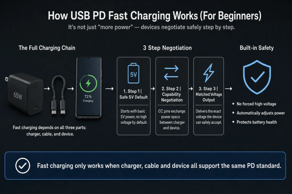
5.1 USB Power Delivery (USB PD)
USB PD communication takes place over the CC pin.
Since the correct CC connection has already been identified, power negotiation works the same whether the plug is inserted normally or upside down.
5.2 DisplayPort Alternate Mode
DisplayPort Alt Mode and other supported Alternate Modes reuse the high-speed signal lanes.
Because those lanes have already been automatically routed, video output behaves exactly the same in either orientation.
5.3 Thunderbolt
Thunderbolt 3, Thunderbolt 4 and Thunderbolt 5 all use the USB Type-C connector as their physical interface.
Their high-speed data transfer, video output and PCIe tunneling all work with USB-C’s reversible connector design.
Note: Thunderbolt is a separate protocol that uses the USB-C connector. Not every USB-C port supports Thunderbolt.
6. Reliability and Safety
6.1 Long Service Life
The USB Type-C specification requires a minimum insertion and removal life of 10,000 cycles.
The double-sided spring contact design also helps distribute wear more evenly, improving long-term durability.
6.2 Safe Power Sequence
When a cable is inserted, the devices first establish a valid CC connection.
Only after this connection has been confirmed does the source enable normal power delivery according to the USB Type-C specification.
This sequence improves the safety of hot plugging.
6.3 Invalid Connection Protection
If no valid CC connection is detected—for example, because the plug is not fully inserted or the connection is abnormal—the source does not enable normal VBUS power delivery.
This helps reduce the risk of accidental power application.
7. Why Can’t USB-A Be Reversible?
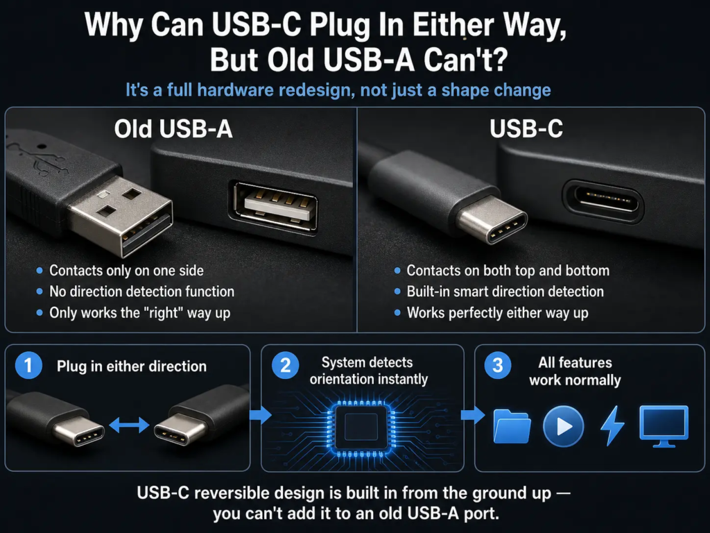
USB-A was never designed for reversible insertion.
There are two main reasons.
Physical Design
USB-A has a rectangular keyed shape with electrical contacts on only one side.
Its connector is not rotationally symmetric, so it can only be inserted in one orientation.
No Detection or Switching Mechanism
USB-A has no CC pins and no mechanism for detecting plug orientation.
It also lacks the internal signal routing used by USB-C.
As a result, USB-A must always be inserted in the correct direction.
Quick Summary
- USB-C’s reversible design is the result of mechanical symmetry, CC-based orientation detection, automatic signal routing, and protocol support working together.
- A 24-contact connector with 180-degree rotational symmetry provides the physical foundation.
- CC pins determine plug orientation, device roles, and power negotiation.
- USB 2.0 signals naturally work in either orientation, while high-speed signals are automatically routed by internal circuitry.
- USB PD, DisplayPort Alt Mode, USB4 and Thunderbolt all function normally regardless of plug orientation (if supported by the device).
- Long service life and controlled power sequencing make USB-C both convenient and reliable.