
Have you ever had this experience: with the same USB-C cable, one side of the plug triggers fast charging on your phone, but flipping it over only gives slow charging? Or you clearly bought a fast charging cable rated at 100W, but it never reaches full power when connected to a laptop? Behind these seemingly inexplicable problems, there is often a pair of unremarkable pins in the USB-C interface — the CC configuration channel.
Many people use USB-C every day, but they don’t know that CC is the core negotiation entry of the entire interface: reversible insertion identification, fast charging negotiation, video output, and Thunderbolt mode switching all rely on it to coordinate. In this article, we will start from the most basic concepts, cover daily purchase pitfalls to avoid, common fault troubleshooting, and then hardware design precautions, to thoroughly explain all CC-related knowledge at once.
1. What is CC: USB-C’s Connection and Negotiation Entry
The official name of CC is Configuration Channel. You can think of it as the “connection detector + negotiation telephone line” in the USB-C interface: the moment a device is plugged in, it first determines whether there is a connected peer, whether the plug is inserted right-side up or upside down, who supplies power and who receives power, and how much current can be provided by default. After confirming the basic information, it is responsible for advanced negotiations such as PD fast charging, alternate mode, and cable capability reading.
Its core positioning is “identification, negotiation, control” — it neither carries large current nor transmits high-speed data, which is what many people easily confuse. To clarify the positioning of CC, we first need to distinguish the division of labor of several types of core pins in the USB-C interface:
- VBUS: Main power supply channel, default 5V, can be raised to higher voltage after PD negotiation, all large current flows through here
- GND: Reference ground for power and signals, also the return path for large current
- D+/D-: USB 2.0 data channel, also used in some older charging identification mechanisms
- TX/RX high-speed differential pairs: Transmission path for high-speed signals such as USB 3.x, USB4, Thunderbolt, DisplayPort Alternate Mode, etc. Video alternate mode also mainly reuses this set of lines
- SBU: Full name Sideband Use pins, commonly used for DisplayPort auxiliary channels, some alternate modes or special accessories, not the main negotiation channel for PD
- CC: Responsible for connection detection, orientation identification, role identification, default current declaration, PD communication, alternate mode triggering, and cable electronic marker reading
You may ask: Traditional USB has been used for so many years without CC pins, why does USB-C have to add this pair of pins? In fact, this is to solve several core limitations of traditional USB interfaces: First, traditional USB interfaces have a fixed orientation and cannot natively support reversible insertion, and the symmetrical design of CC1/CC2 can just determine the insertion direction; Second, the power supply capability expression of traditional USB is very limited, while CC can not only declare different levels of default 5V current, but also serve as the negotiation channel for PD fast charging; Third, the roles of traditional USB interfaces are mostly fixed, either as power supply/host end or power receiving/device end, while CC can support the identification and switching of multiple roles such as Source/Sink, DFP/UFP, DRP, etc.; Fourth, USB-C is an “all-in-one port” — the same interface may need to undertake multiple functions such as charging, data, video, docking station, Thunderbolt/USB4, etc. CC must be responsible for letting the devices at both ends confirm whether they can enter the corresponding mode. It should also be added here: Traditional USB is not completely unable to do charging identification. For example, the USB BC protocol and many proprietary fast charging protocols also exist, but they are not the unified negotiation mechanism of USB-C CC.
2. CC1 and CC2: The Core Secret of Reversible Insertion
If you have carefully looked at the inside of a USB-C receptacle, you will find that the upper and lower rows of contacts are symmetrical, and CC1 and CC2 are located at corresponding positions in the upper and lower rows respectively — this is the key to reversible insertion.
The two CC pins are symmetrical, not parallel-connected for enhancement
Many people think that CC1 and CC2 are “one main and one backup”, or connected in parallel to enhance the signal, but neither is correct. CC1 and CC2 on the receptacle have completely symmetrical functions with no priority, and their only function is to identify the insertion direction of the plug.
The plug side of USB-C does not connect both CC1 and CC2 to the cable at the same time. After inserting into the receptacle, only the channel aligned with the plug’s CC contact (either CC1 or CC2) will become the effective communication path, and the other channel will be in an idle state.
There is a very important taboo here: Never short CC1 and CC2 directly. Short-circuiting will directly destroy the orientation identification logic, and may also cause abnormal VCONN power supply and PD controller misjudgment of cable or accessory status. In mild cases, functions will fail, and in severe cases, compatibility problems will occur. Even for simple devices that only receive power, the two CC pins must be handled separately according to the specification, and cannot be directly connected together for convenience.
The Complete Process of Reversible Insertion Identification
The entire identification process is actually very fast, you can’t feel it at all:
Before insertion, the power supply end (Source, such as a charger, a computer’s power port) will present a pull-up resistor Rp on the CC pin, the power receiving end (Sink, such as a mobile phone, a mobile hard drive) will present a pull-down resistor Rd, and a DRP device that can both supply and receive power will switch back and forth between the two states for detection.
The moment of insertion, the receptacle’s controller will simultaneously detect the voltage status of CC1 and CC2: if a valid Rp/Rd combination is detected on CC1, it means the plug is inserted right-side up; if detected on CC2, it is inserted upside down.
After confirming the direction, the controller will do three things: First, use the valid CC channel as the path for subsequent PD communication; Second, switch the multiplexing relationship of the high-speed differential pairs according to the direction to ensure normal data and video transmission; Third, if there is an E-Marker chip in the cable or it is an active cable, power the cable through the idle CC pin, which is what we often call VCONN.
The Role of the Idle CC: VCONN Cable Power Supply
Many people don’t know that the idle CC channel is not a useless “spare tire” — it has another important function: as the power supply path for VCONN.
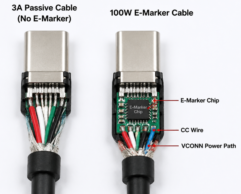
Simply put, VCONN is a small power supply provided by the device end to the internal electronic components of the cable through the CC pin. It mainly supplies power to three types of components: the E-Marker electronic identification chip in the cable, the signal amplification chip inside active cables, and the control chips of some active adapters.
When is VCONN needed? For example, 5A 100W cables, USB4 cables, Thunderbolt cables, active extension cables — these cables have electronic chips inside and all require VCONN power supply to work. Ordinary 3A passive cables without E-Marker have no chips inside, so naturally they don’t need VCONN.
3. Basic Electrical Logic of CC: Identity Identification with Three Resistors
CC communication may seem complicated, but in fact, the most basic identity identification relies entirely on three resistors: Rp, Rd, Ra. You can think of them as the “identity tags” that devices hang on the CC line — the other side only needs to measure the voltage to know who you are.
Three Identity Signals: Rp, Rd, Ra
- Rp: Pull-up resistor, connected to the CC pin of the power supply end (Source), meaning “I can supply power”. For example, chargers, computer power ports, and power bank output ports all have Rp.
- Rd: Pull-down resistor, connected to the CC pin of the power receiving end (Sink), meaning “I need power”. For example, mobile phones, earphones, mobile hard drives, and laptops in power receiving state all have Rd.
- Ra: Accessory identification resistor, generally used in special accessories (such as audio adapters, debugging accessories) or VCONN-related detection scenarios, meaning “I am a special accessory and need special handling”.
When the power supply end and the power receiving end are connected together, Rp and Rd will form a voltage divider, and the voltage on the CC line will fall within a specific range. The controller can then judge based on this voltage: whether a device is inserted, whether the other party is supplying or receiving power, which CC pin is valid (that is, the reversible insertion direction), and how much default current the power supply end can provide.
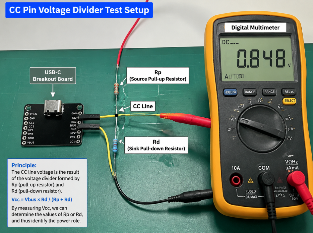
It should be reminded here: the specific voltage threshold will vary with different USB specification versions and chip designs, so there is no need to memorize them by rote. Actual judgment shall be based on the official USB Type-C specification and the chip datasheet.
USB-C Default Current Levels: Fast Charging Is Not Only Possible with PD
Many people think that USB-C fast charging relies entirely on PD. In fact, before PD negotiation, CC can declare three default current capabilities at 5V through different resistance values of Rp:
- Default USB Power: Default USB power supply capability. The actual available current is related to USB 2.0/USB 3.x, whether enumeration is performed, port power supply strategy and device design; the common 500mA/900mA in the traditional USB context can only be used as a reference, and Default cannot be fixedly understood as a certain current value.
- 1.5A at 5V: Type-C default enhanced level, with stronger power supply capability than ordinary USB.
- 3A at 5V: The highest level of Type-C default current. Ordinary dual-C cables without E-Marker have a maximum default current capability of 3A; if both parties subsequently complete PD negotiation and raise the voltage to 20V, this type of cable usually corresponds to a maximum power limit of 60W in common PD scenarios.
It must be clearly distinguished here: default current declaration is not equal to PD fast charging. Default current is the basic capability at 5V, which does not require complex protocol negotiation and can be used immediately after plugging in; while PD fast charging is based on this, by transmitting dedicated PD protocol messages through CC, further negotiating voltages of 9V, 15V, 20V or even higher to achieve greater power.
Three Working Stages of CC
The working process of CC can be divided into three stages, from simple to complex:
- Unconnected stage: No valid Rp/Rd combination is detected, the port is in standby or periodic detection state, with very low power consumption.
- Initial connection stage: When the device is just plugged in, insertion detection, orientation identification, power supply/power receiving role judgment, and default current capability judgment are completed quickly. At this time, charging with 5V default current is already possible.
- Protocol communication stage: If both sides support USB PD, PD messages will be transmitted on the CC line using BMC coding, which is what we call “fast charging negotiation”. In addition to voltage and current, advanced functions such as role switching, alternate mode, and cable capability reading can also be negotiated.
Speaking of this, we can clarify the relationship between CC and PD: CC is the physical communication channel of the PD protocol, and PD is the negotiation protocol running on CC. For example, CC is the telephone line, and PD is the “power supply contract” negotiated on the phone — without a telephone line, you can’t negotiate a contract, but the telephone line itself is not equal to the contract.
We also need to correct a common misconception: not all PD fast charging requires a cable with a chip. Ordinary 3A passive cables can support up to 60W PD charging. Only high-power or high-speed scenarios such as 5A/100W, EPR 140W/180W/240W, USB4, and Thunderbolt require cables with E-Marker chips to declare their capabilities.
4. 6 Core Functions of CC, All of Which You Use Every Day
The functions of CC sound very abstract, but in fact each one corresponds to your daily USB-C usage scenarios:
1. Insertion Detection
The first function of CC is to determine whether a device is actually plugged into the interface, rather than dust entering or accidental contact with metal. When you plug in a charger and your phone immediately turns on the screen to charge, or when you plug in a docking station and your computer immediately recognizes peripherals, it is CC that first detects a valid connection before starting subsequent functions. If the interface is loose or too much dust causes poor CC contact, there will be situations where there is no response after plugging in or repeated disconnections.
2. Reversible Insertion Orientation Identification
This is the most familiar function: USB-C can be used regardless of insertion direction. Essentially, it relies on which of CC1 and CC2 detects a valid signal to determine the plug direction, and then switches the corresponding relationship of internal high-speed lines. If one side can fast charge and the other can only slow charge, or one side can display and the other has no response, it is most likely a problem with the contact of one CC channel or the cable.
3. Power Role Identification and Switching
CC can also determine who is the power supplier and who is the power receiver, and supports dynamic switching. For example, when a charger powers a mobile phone, the mobile phone is the power receiving end; when a laptop reverse-charges a mobile phone, the laptop becomes the power supply end; a power bank can both charge a mobile phone and be charged by a charger. These two-way role switching are all realized by CC’s DRP (Dual Role Power) mechanism.
Two related concepts are added here: DFP and UFP are data-oriented roles, corresponding to host and device; Source and Sink are power-oriented roles, corresponding to power supply and power reception. The two are related but not the same thing, don’t confuse them.
4. Default Current Declaration and PD Power Negotiation
This is the fast charging function that everyone cares about most: basic 5V default charging can be used immediately after plugging in, and devices that support PD will further negotiate higher voltage and power through CC, such as 9V fast charging for mobile phones, 20V power supply for laptops, and even higher levels of USB PD 3.1 EPR. The specific negotiation logic has been explained earlier. You only need to remember: whether fast charging can reach full power depends on the minimum capability of the device, charger, and cable. If any one does not support it, it will fall back to a lower level.
5. Alternate Mode Triggering
A USB-C port can be used as a charging port, data port, and video port, relying on “Alternate Mode”, and the negotiation to enter Alternate Mode is completed through CC. For example, when you use USB-C to connect a monitor to output images, connect a docking station to use a monitor, network port, and USB devices at the same time, or when Thunderbolt/USB4 peripherals enter high-speed mode, CC first confirms with the other side “I can enter this mode, do you also support it?”, and only after reaching an agreement will it switch to the corresponding mode.
As the saying goes: CC is only responsible for negotiation, and the actual video and high-speed data still go through TX/RX high-speed differential pairs. The device, cable, and docking station must all support the corresponding mode.
6. Reading Cable Capability Information
Why do some 100W fast charging cables only deliver 60W when plugged in? It is very likely that there is no E-Marker chip in the cable, and the device cannot read the cable’s capability, so it dares not provide 5A current.
E-Marker is the “ID chip” in the cable, which stores information such as the cable’s rated current, supported high-speed rate, whether it is an active cable, and whether it supports EPR high power. Before the device runs high-power or high-speed mode, it will power the E-Marker through VCONN, read this information, and confirm that the cable can withstand it before enabling the corresponding function. In scenarios such as 100W/5A, 140W/240W EPR, USB4, Thunderbolt, and high-bandwidth video output, the device usually needs to confirm the cable capability, and the common method is to power the E-Marker and read the information; whether it must be read and what information to read depends on the cable type, device strategy, and target mode.
5. Avoiding Pitfalls When Buying Cables and Adapters: How Many CC-Related Pitfalls Have You Stepped On?
Many people only look at “whether it is a Type-C port” when choosing a USB-C cable, and when they get it home, either the fast charging can’t reach full power, or it can’t transmit data, or it can’t connect to a monitor — most of these problems are related to CC and the cable’s configuration. We have sorted common cable types and CC characteristics into a table for your comparison:
| Cable Type | CC/E-Marker Configuration | Power Limit | Applicable Scenarios |
|---|---|---|---|
| Ordinary 3A USB-C to C Cable | Has CC channel, no E-Marker; can complete connection identification and ordinary PD communication, does not mean it has USB 3.x or video capability | Up to 60W (20V 3A) | Mobile phone fast charging, tablet charging, ordinary PD charging, USB 2.0/3.x data |
| 5A/100W PD Cable | Has CC channel, with 5A E-Marker | Up to 100W (20V 5A) | Laptop PD charging, high-power mobile phone fast charging |
| USB PD 3.1 EPR High-Power Cable | Has CC channel, with EPR-certified 5A E-Marker | Up to 240W (48V 5A) | 140W/180W/240W high-power device charging |
| Full-Feature USB-C Cable | Has CC channel, with USB 3.x high-speed differential pairs; whether it has E-Marker depends on the rated current | Determined by the cable’s rated current, commonly 60W (3A)/100W (5A) | PD charging + USB 3.x high-speed data + DP video output |
| USB4/Thunderbolt 3/4 Cable | Has CC + certified E-Marker, high-speed line meets standards | Depends on cable labeling and E-Marker: may support 60W, 100W or EPR 240W; high-speed certification does not automatically equal maximum power | 40Gbps/80Gbps high-speed data, Thunderbolt devices, high-specification video |
| USB-A to USB-C Cable | The C end usually uses a fixed Rp to let USB-C devices identify it as a power source; does not form a complete C-to-C CC/PD link | Usually only 5V power supply, specific current depends on USB-A port/charger/cable/device strategy; does not support standard USB PD high-voltage negotiation | Ordinary charging, USB 2.0 data |
Power, data, and video in the table are three independent indicators, which need to be checked separately when purchasing.
Types of Most Common Pitfalls
1. Special Limitations of USB-A to C Cables/Adapters
USB-A ports have no CC pins at all, so the CC function of A-to-C cables is realized by a fixed Rp resistor in the C-end plug. It can only declare the power supply capability at 5V and cannot support standard USB PD high-voltage negotiation. If the Rp resistance of a low-quality A-to-C cable is incorrect, it may also cause the device to misjudge the power supply capability, leading to overcurrent or compatibility problems. If you want to use PD fast charging, try to choose dual-C port cables.
2. CC Cut Corners in Low-Quality Cables
Many cheap “100W fast charging cables” are actually falsely labeled, and there are especially many CC-related problems:
- CC line is broken or not soldered properly: manifested as no response after plugging in, only low-power charging, and some devices cannot be used at all
- Incorrect Rp/Rd resistance: manifested as false power supply capability reporting, fast charging negotiation failure, repeated disconnections
- E-Marker is falsely labeled or not present at all: labeled 100W/240W, but actually only runs 3A/60W
- Problem with VCONN path: cannot read E-Marker, high-speed cables or active cables work unstable
- Incorrect orientation handling of adapters: different functions for reversible insertion, for example, one side can display and the other cannot
We need to correct a misconception here: the current flowing through CC itself is very small, so CC-related faults have almost nothing to do with “too thin wire diameter”, and are mostly problems such as poor contact, incorrect resistance, poor soldering, and falsely labeled chips.
3. CC Logic of Docking Stations and Multi-Port Chargers
Formal docking stations have a dedicated PD controller. The upstream port negotiates power supply, data roles and video mode with the computer, and the downstream ports handle peripherals, monitors, and charging output respectively. If the docking station has insufficient power supply, functions may be downgraded.
Each C port of a multi-port charger generally has independent CC/PD negotiation logic. When you plug in a second device, the charger may reallocate the total power, causing the first device to briefly stop charging and then resume — this is normal power reallocation, not a fault.
4. Compatibility Boundaries You Must Know
Many people think that “having a USB-C port means supporting everything”, but that’s not the case at all:
- USB-C is the interface form, PD is the power supply protocol. The two are related but not equivalent. Having a C port does not necessarily support PD fast charging
- Supporting PD fast charging does not necessarily support video output, nor does it necessarily support Thunderbolt or USB4
- Supporting 100W charging does not mean supporting high-speed data. Power capability and data capability are two independent indicators
- Some proprietary fast charging protocols use D+/D-, some use CC, but when used across brands, most will fall back to standard PD or ordinary 5V low power
- CC does not directly determine data bandwidth, but it affects whether advanced modes such as USB4, Thunderbolt, and DP Alt Mode can be entered
Methods for Judging CC-Related Cables When Purchasing
Actually, choosing a cable is very simple, just match it according to your needs:
- Look at power: For within 60W, an ordinary 3A cable is enough; for 100W, choose a cable with 5A E-Marker; for 140W/240W, choose a cable that supports USB PD 3.1 EPR
- Look at function: If you only charge, you don’t need to buy expensive high-speed cables; if you need to transfer large files, look for labels such as USB 3.2, USB4, 40Gbps/80Gbps; if you need to connect a monitor, check if there is DP Alt Mode, USB4 or Thunderbolt compatibility instructions
- Look at certification and parameters: Prioritize products with clearly marked parameters, USB-IF certification or Thunderbolt certification, and reliable brands. Try not to buy those that only write “Type-C fast charging cable” without marking power, current, data rate, or E-Marker.
Precautions for Daily Protection of CC Pins
Although CC pins are small, they are very troublesome if broken. Pay attention to the following points in daily use:
- Do not plug or unplug violently, as it is easy to deform the contacts of the receptacle, resulting in poor CC contact
- Keep the interface clean and dry. Liquids, sweat, and metal shavings may cause CC misjudgment or corrode the contacts
- When cleaning the interface, do not scrape hard with a metal needle, as it is easy to scratch the contacts. Just use an air blower, soft brush, or dry lint-free cloth to gently handle it
- Do not let the cable root be bent at a large angle for a long time, as the internal CC line or high-speed line may break
- If the interface is hot, has an odor, or repeatedly disconnects, stop using it immediately for inspection, do not force it to use
6. How to Troubleshoot CC-Related Faults: From Beginner to Advanced
When encountering abnormal USB-C functions, many people directly blame the charger or the device for being broken. In fact, most of the time it is a CC-related problem, and most of them you can troubleshoot by yourself.
Confirm “Capability Boundaries” Before Troubleshooting
Many so-called “faults” are actually incompatibilities, not really broken. Confirm the following points before troubleshooting:
- Does the device’s USB-C port support PD fast charging and video output? Some USB-C ports of some mobile phones, tablets or laptops only support charging and ordinary data, and do not support DP Alt Mode; different C ports of the same laptop may also have different capabilities
- Does the charger have the power level you need? For example, if a mobile phone requires 30W PPS, the charger must have the corresponding PDO/PPS level
- Can the cable support the target power/rate/mode? For example, 100W requires a 5A E-Marker cable, and 4K 60Hz video requires a full-feature cable or USB4/Thunderbolt cable
- Does the docking station need an external power supply? Many docking stations will disable high-speed or video functions when power supply is insufficient
Typical Characteristics of CC Faults
If the following situations occur, it is most likely related to CC:
- The same port behaves differently when inserted right-side up and upside down, for example, one side can fast charge and the other can only slow charge; one side can display and the other has no response
- Can charge normally at 5V, but cannot trigger PD fast charging, and returns to normal after replacing a confirmed good cable
- A cable labeled high power only runs 3A/60W when plugged in, and cannot read E-Marker information
- Flickers and disconnects repeatedly when connecting to a monitor or docking station, and it works after replacing a full-feature cable
- When a new device is plugged into a multi-port charger, it briefly disconnects and recovers quickly — this is generally power reallocation, not a fault
Troubleshooting Steps for Ordinary Users
No professional tools needed, follow these steps, and you can basically locate 80% of the problems:
- First confirm that the device, charger, and cable all support the function you need, to eliminate the problem of insufficient capability
- Replace with a confirmed qualified cable for testing, and prioritize eliminating cable problems — after all, cables are the easiest to break and the easiest to be falsely labeled
- Insert the plug right-side up and upside down once each, test the functions respectively. If only one direction has a problem, it is basically a CC-related contact or cable fault
- Try another charger or another C port of the device to determine whether the problem is at the power supply end or the power receiving end
- Check whether there is dust, foreign matter, oxidation, looseness or signs of liquid ingress in the interface. Many times, just cleaning the dust will fix it
- Gently clean the interface with a dry soft brush or air blower, then retest. Never use sharp metal objects to scrape inside, as it is easy to scratch the contacts
How to Judge Whether It’s a Cable Problem or an Interface Problem
- Cable end problem: Same device and same charger, works after changing the cable; the original cable also has problems when plugged into other devices; labeled high power but cannot read E-Marker; only one end has reversible insertion problems, the other end is normal. Also note that if it can only charge but not transmit data, it is not necessarily a broken CC. It may be that this cable is originally a USB 2.0 or pure charging cable, and does not have high-speed data pins at all.
- Interface end problem: If several qualified cables have problems in the same direction of the same device, it is most likely that the corresponding CC contact of the device’s receptacle is broken; unstable insertion and repeated disconnections after dust ingress are mostly poor CC contact; fast charging fails after liquid ingress, which may be due to corrosion of CC contacts or protection triggered by the PD controller; if reversible insertion abnormality occurs just after replacing the receptacle, it may be that CC1/CC2 are soldered reversely during maintenance, or the wiring is connected incorrectly.
Engineering/Repair Level Testing Methods
If you have professional tools, you can further troubleshoot:
- Use a USB-C tester (also called a power meter) to check whether PD can be identified, the current voltage and current, and whether the cable is identified as 5A
- Use a PD trigger or PD analyzer to view the negotiation processes such as PDO, Request, and Contract to see which step has the problem
- Use a multimeter or oscilloscope to measure the voltage status of the CC pin, and judge against the thresholds in the Type-C specification and chip manual
- Use a cable tester to check the continuity of CC, whether E-Marker can be read normally, and whether the data line is broken
- If it is a mass-produced product, also check CC routing, ESD devices, resistance values, PD controller firmware, VCONN power supply capability and abnormal protection logic
Several Common Misconceptions in Troubleshooting
- Being able to charge means CC is fine: Wrong. It may be that only the basic 5V low-power function is normal, and advanced functions such as PD negotiation, Alt Mode, and E-Marker reading may already be broken.
- Being able to charge with both insertion directions means CC is completely normal: Wrong. Charging only requires basic CC functions, and advanced functions such as fast charging, video, and high-speed data may only work in one direction.
- Not being able to connect to a monitor must be a broken CC: Wrong. You also need to confirm whether the device supports DP Alt Mode, whether the cable is a full-feature cable, and whether the monitor/docking station is compatible. Many times it is a lack of support, not a breakdown.
- A 100W cable must be able to run USB4: Wrong. Power and data are two independent indicators. 100W only indicates power supply capability, not high-speed data capability. Many 100W cables are only USB 2.0.
- PD fast charging failure must be a broken charger: Wrong. Devices, cables, E-Marker, interface contamination, protocol incompatibility, and device temperature control strategies may all cause fast charging to fall back to a lower level.
7. Hardware Design and Routing: Precautions for CC Pins
If you are engaged in hardware DIY, small product development or repair, this part of the content can help you avoid many CC-related pitfalls, which are all summaries of experience from actual mistakes.
1. CC1 and CC2 Must Never Be Short-Circuited Casually
Whether it is a power supply device or a power receiving device, CC1 and CC2 of the receptacle must be connected to the Type-C/PD controller or the corresponding detection circuit respectively, and must never be directly short-circuited. Short-circuiting will cause orientation identification failure, VCONN control confusion, and accessory identification errors, and in severe cases, may damage the PD controller. Even for the simplest pure power receiving device, Rd must be placed according to the specification or an integrated Type-C controller must be used, and the two CCs cannot be directly connected together for convenience.
2. Choose the Right Rp/Rd Resistors and Controller
- The power supply end (Source) must correctly set the resistance value of Rp to declare the corresponding default current capability, and cannot just pick a resistor to use
- The power receiving end (Sink) must correctly place Rd and wait for the capability declaration of the power supply end
- Dual-role (DRP) devices must use a dedicated PD controller to switch Source/Sink states, and cannot use fixed resistors perfunctorily, otherwise role identification confusion will occur
- If you want to support functions such as PD, PPS, EPR, and Alt Mode, you must choose a PD controller with corresponding capabilities and supporting firmware. Don’t expect low-end controllers to be flashed with advanced functions
3. Points to Note in VCONN Power Supply Design
If your device needs to power E-Marker or active cables, pay attention to the following points when designing VCONN:
- The VCONN power supply path must have overcurrent protection and switch control, and cannot be directly always-on
- Consider which CC channel will become VCONN during reversible insertion, and cannot fixedly assume that a certain CC pin is always VCONN
- The VCONN power supply capability must meet the specification requirements, otherwise there will be problems such as inability to read E-Marker and unstable operation of active cables
4. ESD Protection Devices Cannot Be Chosen Casually
CC pins are exposed to the external interface and are easily damaged by static electricity, so ESD protection must be added. But ESD devices cannot be casually taken from high-speed lines or power lines. You must choose models whose capacitance, leakage current, and clamping characteristics are all compatible with CC/PD communication, otherwise it will lead to unstable PD communication and negotiation failure. Liquid ingress, static electricity, and misplugging low-quality cables are common causes of damage to the CC path and PD controller.
5. Key Points for Routing and Mass Production Testing
Although CC does not carry high-speed data, routing cannot be too casual: try to avoid long-distance winding, stay away from strong interference sources, and do not add unnecessary branches, otherwise it may affect the stability of PD communication.
There is also a very easy mistake to make: the naming of CC1 and CC2 must be clearly checked against the packaging direction of the connector, otherwise the PCB will be mirrored, and after soldering, the reversible insertion logic will be completely reversed, which will be very troublesome during debugging.
During mass production testing, these items must be covered: forward/reverse insertion connection detection, default current identification, PD negotiation, 5A cable identification, DP Alt Mode, USB4 or Thunderbolt mode entry, abnormal cable and overcurrent protection, otherwise batch problems will be very troublesome.
8. Clarify CC’s Capability Boundaries with One Table
Many people confuse the functions of CC after learning. We have sorted out what it can and cannot do into a table for your quick comparison:
| What CC Can Do | What CC Cannot Do |
|---|---|
| Detect device insertion and removal | Directly carry high-power charging current (current flows through VBUS/GND) |
| Judge the reversible insertion direction of the plug | Directly transmit USB high-speed data (data goes through TX/RX differential pairs) |
| Identify power supply/power receiving roles, support role switching | Independently determine video quality and data rate |
| Declare Default/1.5A/3A default current at 5V | Make up for functions not supported by the device, cable, or docking station itself |
| Carry USB PD protocol negotiation messages | Ensure cross-brand compatibility of all proprietary fast charging protocols |
| Negotiate and trigger advanced modes such as Alternate Mode, USB4, Thunderbolt, etc. | |
| Read E-Marker cable capability information | |
| Control VCONN to power cable electronic components |
What Can You Judge Independently After Learning This?
After reading this article, you should have been able to sort out the core logic related to CC:
- Can clearly explain the relationship between CC, CC1/CC2, VCONN, E-Marker, and PD: CC is the negotiation channel, CC1/CC2 manage reversible insertion, VCONN powers the cable chip, E-Marker is the cable’s ID card, and PD is the power supply protocol running on CC
- Can explain why USB-C works with both insertion directions, and why some cables work on one side but not the other
- Can distinguish the difference between default current declaration and PD fast charging, and know why ordinary 3A cables can only reach up to 60W
- Can understand the parameters of high-power cables, know that 100W cables need to pay attention to 5A E-Marker; 140W/180W/240W high-power cables also need to pay attention to USB PD 3.1 EPR, 5A E-Marker, and whether the device and charger support the corresponding EPR levels
- When encountering problems of “can charge but cannot fast charge/cannot display/cannot high-speed transmit”, can troubleshoot step by step whether it is a problem with the device, cable, or interface
- When doing hardware design or repair, can avoid common pitfalls such as CC1/CC2 short circuit, VCONN design error, incorrect Rp/Rd resistance, and random selection of ESD devices
The CC pin of USB-C looks inconspicuous, but it is the core negotiation hub of the entire interface — from reversible insertion identification, to 240W fast charging contract negotiation, and the entry triggering of high-speed modes such as USB4/Thunderbolt, all are inseparable from CC; but the actual large current still flows through VBUS/GND, and high-speed data still goes through high-speed differential pairs. After understanding the working logic of CC, you won’t have to step on inexplicable pitfalls when choosing cables, troubleshooting faults, or using docking stations in the future.