
Chapter 1 Introduction: Evolution of Fast Charging and Core Technical Conflicts
1.1 Background of Fast Charging for Mobile Devices
Modern smartphones and tablets feature high-refresh screens, 5G communication and powerful processors, which drastically increase power consumption. Device batteries have also become larger in capacity. Traditional 5V slow charging used to take two to three hours to fully charge a phone, failing to meet users’ demand for quick power top-ups. Fast charging technology has therefore developed rapidly.
Charging power has risen from the initial 10W to 67W, 120W and even 200W. However, users often encounter obvious drawbacks: devices heat up severely under high-power charging, charging speed slows sharply in the later stage, and long-term high-temperature charging accelerates battery aging. Balancing charging speed, device temperature and battery lifespan has become the core challenge of the fast-charging industry.
1.2 Two Main Fast-Charging Routes and Their Inherent Drawbacks
There are two mainstream fast-charging technical routes, both with obvious limitations:
High voltage & low current: Chargers output fixed high voltages (9V/12V/20V) to boost power. This method generates less heat on charging cables and costs less, but phones need to convert high voltage down to low voltage for batteries. The larger the voltage gap, the more heat is produced inside the phone. High temperatures trigger thermal throttling, slowing down charging and damaging batteries over time.
Low voltage & high current: Low voltage close to battery voltage with large current reduces phone heat. However, traditional fast charging only supports fixed voltage gears, which cannot precisely match real-time battery demands. Excessively large current also puts heavy pressure on charging cables and ports.
1.3 Core Value of the PPS + Charge Pump Architecture
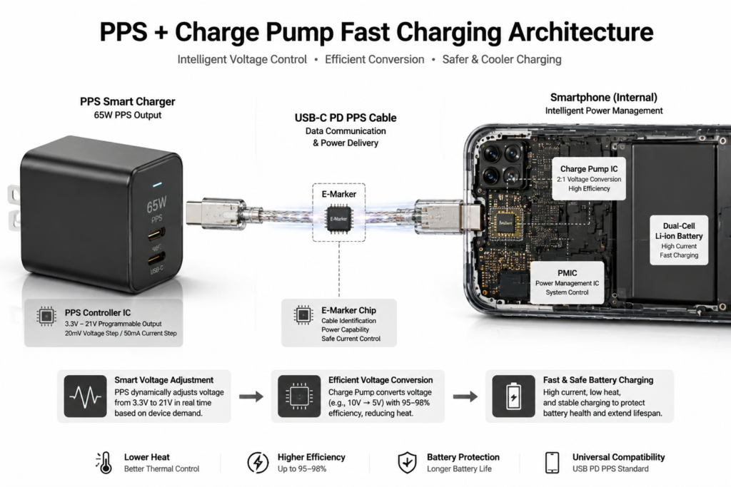
To solve overheating, slow charging and battery damage simultaneously, the industry created a combined hardware & software solution: PPS fast-charging protocol paired with charge pump hardware.
Simply put, PPS intelligently adjusts output voltage on the charger side, while charge pumps efficiently convert voltage inside phones. The two technologies complement each other, avoiding high temperature from large voltage gaps and overload current issues. This balanced solution optimizes charging speed, temperature control and battery protection, and has become the standard fast-charging scheme for mid-to-high-end smartphones.
1.4 Article Framework and Technical Scope
This article adopts plain language without complex formulas, based on official public charging standards, mass-produced charging chips and real test data of consumer devices. It breaks down the working logic of PPS protocols and charge pump hardware, explains how they cooperate to deliver fast charging, shares practical cases on mobile devices, objectively introduces existing technical limitations and future upgrade directions, and is easy to understand for ordinary users.
Chapter 2 In-depth Analysis of PPS Programmable Power Supply Protocol
2.1 Definition, Origin and Positioning of PPS
PPS (Programmable Power Supply) is a universal public charging standard released by USB-IF in 2017, serving as an extended function of the USB PD fast-charging system.
Before PPS, each smartphone brand launched proprietary fast-charging protocols; third-party chargers could only run slow charging instead of full-speed fast charging. As an open cross-brand standard, PPS enables full-speed fast charging with any compliant PPS charger for all compatible phones, solving the compatibility problem of proprietary chargers.
2.2 Official Core Technical Parameters
Per official specifications, PPS chargers support output voltage ranging from 3.3V to 21V, with ultra-fine adjustment steps of 20mV for voltage and 50mA for current.
To make it easier to understand: old fast charging works like stairs with only several fixed voltage steps, while PPS acts as a smooth slope with continuous micro-adjustment, matching battery demands in every charging phase.
2.3 Communication Process and Working Principle of PPS
2.3.1 Basic Communication Mechanism
Charging cables contain a dedicated communication pin. Once a phone connects to a PPS charger, the two devices continuously exchange data. The phone transmits real-time information including battery voltage, device temperature and maximum acceptable charging current, and the charger adjusts output parameters accordingly.
2.3.2 Dynamic On-demand Power Supply Logic
A complete lithium battery charging cycle has three stages:
Low battery stage: The battery can bear large current. PPS adjusts voltage to maximize charging current for rapid power recovery.
Medium battery stage: As the battery saturates, PPS slightly reduces voltage and current to avoid temperature rise.
Full-charge finishing stage: Switch to tiny trickle charging to prevent overcharging and protect battery health.
2.4 Comparison Between PPS and Traditional Fast-Charging Protocols (QC / Standard PD)
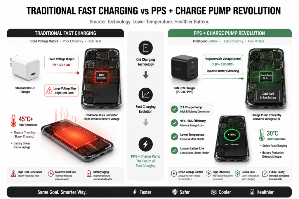
Traditional protocols only provide fixed voltage gears. Sudden voltage jumps during gear switching create mismatches with battery demands, causing severe conversion heat loss.
PPS supports stepless continuous voltage adjustment, keeping voltage consistent with real-time battery status, cutting heat loss and delivering better temperature control. It also works with all Type-C devices with stronger universality.
| Comparison Dimension | PPS Protocol | Traditional QC / Standard PD Protocol |
|---|---|---|
| Voltage Adjustment Mode | Stepless continuous adjustment | Fixed voltage gears (5V/9V/12V/20V) |
| Voltage Adjustment Step | 20mV ultra-fine adjustment | Fixed gear jump (3V/4V gap between gears) |
| Real-time Matching | Dynamic real-time matching with battery status | Fixed output, cannot adapt to real-time battery changes |
| Conversion Heat Loss | Low (small voltage mismatch) | High (large voltage gap, obvious heat generation) |
| Cross-Brand Compatibility | Universal cross-brand standard | Proprietary brand locks, poor compatibility |
| Temperature Control | Excellent, avoids thermal throttling | Average, easy to trigger temperature-related speed reduction |
2.5 Advantages and Inherent Limitations of PPS
Advantages: Cross-brand compatibility without exclusive original chargers; better temperature control to slow battery degradation; compatible with phones, tablets and laptops of various power ratings.
Limitations: PPS is only a communication regulation system without voltage conversion capability, so it must work with internal conversion hardware in phones to deliver full performance; low-quality charging cables block communication and downgrade fast charging to ordinary slow charging.
2.6 Main Application Scenarios of PPS
Mid-to-high-end Android smartphones, foldable phones and gaming phones with Type-C ports; portable power banks, car chargers and GaN desktop chargers; lightweight laptops and tablets with medium-low power demands.
Chapter 3 Working Principle of Charge Pump Fast-Charging Hardware
3.1 Definition and Core Positioning of Charge Pumps
A charge pump is voltage conversion hardware installed on phone motherboards, which relies on capacitors to store and transfer electric energy for voltage transformation.
It acts as an efficient step-down converter inside mobile devices, cooperating with PPS chargers to convert high input voltage into low voltage suitable for batteries while minimizing heat generation.
3.2 Essential Differences Between Charge Pumps and Traditional Inductive Buck Converters
Older phones widely used inductive buck modules relying on coils for energy conversion. Coils bring extra energy loss, obvious heat generation, larger component size and minor electromagnetic interference.
Charge pumps operate without coils, relying solely on capacitors to cut energy loss, lower device temperature and shrink hardware size for slimmer phones. The only downside is that charge pumps maintain high efficiency only within a specific voltage range, requiring precise voltage adjustment from PPS.
3.3 Basic Working Mechanism (Taking Classic 2:1 Step-Down Topology as Example)
The 2:1 step-down charge pump, the most widely adopted design in smartphones, operates in two repeating cycles:
Energy storage phase: Capacitors connect in series to the charger input, evenly splitting input voltage for energy storage.
Discharge phase: Circuit switches flip to connect capacitors in parallel to supply power to the battery. Output voltage equals half of input voltage, while output current doubles.
Example: A 10V input from the charger turns into 5V for the battery via a 2:1 charge pump; 5A input current becomes 10A large charging current, realizing low-voltage high-current fast charging.
3.4 Main Charge Pump Topologies and Their Features
3.4.1 2:1 Half-Voltage Charge Pump (Mainstream Standard)
Standard configuration for most single-cell phones with stable conversion efficiency between 95% and 98%. Simple and reliable, adopted in all 30W–80W fast-charging devices.
3.4.2 3:1 / 4:1 Multi-Stage Step-Down Charge Pumps
Applied in high-power fast-charging systems above 100W, converting 20V high voltage directly to 5V, reducing current load and heat on charging cables.
3.4.3 Multi-Phase Interleaved & Reconfigurable Charge Pumps
Two or more charge pumps operate simultaneously to share charging load and reduce single-chip heat; automatically switch voltage division ratios to adapt to fluctuating charger voltage.
3.4.4 Adiabatic Resonant Charge Pumps (Next-Generation Technology)
Optimized circuit structure minimizes energy loss during switching, with peak conversion efficiency approaching 99%, the core hardware for future ultra-high-power low-temperature fast charging.
3.5 Efficiency Characteristics and Loss Sources of Charge Pumps
Normal operating efficiency of charge pumps ranges from 90% to 98%. Energy loss mainly comes from capacitor internal resistance, switch on-resistance and minor loss from high-frequency switching.
Voltage matching directly determines efficiency: minimal loss occurs when charger output voltage is twice the battery voltage; obvious heat rise happens with large voltage deviation, which explains why charge pumps must pair with PPS protocols.
3.6 Core Value of Charge Pumps in Fast-Charging Systems
Significantly reduce phone heat during charging and avoid thermal throttling; cut cable current by half under equal power, enabling high-power charging with ordinary cables; break power limits to realize 100W+ fast charging and extend full-speed charging duration.
Chapter 4 Cooperation Mechanism of PPS and Charge Pump
4.1 Underlying Logic of Matching (Why They Must Work Together)
Used alone, charge pumps have obvious flaws: efficiency plummets and devices overheat with fixed-gear chargers due to voltage mismatch.
Used alone, PPS cannot step down voltage, and high charger output voltage cannot directly charge batteries.
Combined, the two technologies make up for each other’s weaknesses: PPS continuously fine-tunes voltage to keep charge pumps running at peak efficiency, while charge pumps complete efficient voltage conversion to compensate for PPS’s lack of hardware transformation capacity.
4.2 Complete Full Cooperation Workflow
4.2.1 Handshake Matching Stage
When a phone connects to a PPS charger, the communication pin of the charging cable establishes a connection instantly. The phone transmits battery voltage, temperature and compatible voltage range data, and the charger identifies PPS support of the device.
4.2.2 Dynamic Voltage Matching Stage
The charger continuously adjusts output voltage in tiny increments to maintain double the battery voltage, locking charge pumps in their highest-efficiency operating window.
4.2.3 High-Efficiency Step-Down Charging Stage
The charger outputs matched high voltage, and the charge pump performs 2:1 voltage division to deliver large current directly to the battery with low energy loss and mild device temperature.
4.2.4 Intelligent Finishing Protection Stage
When the battery is nearly full, PPS gradually reduces output power, and charge pumps switch to low-current trickle charging mode to avoid overcharging and battery degradation.
4.3 Core Advantages of the Combined Architecture
Only one round of voltage conversion is needed, lifting charging efficiency by 10%–20% compared with old two-stage buck designs; heat disperses between charger and phone to avoid local overheating; charging curves match native battery characteristics to slow long-term capacity decay; standardized universal design supports full-speed fast charging with third-party PPS chargers.
4.4 Mass-Produced Commercial Chip Solutions
The following table lists the mainstream mass-produced charge pump chips widely used in consumer electronic devices, with real and verified parameters:
| Chip Model | Manufacturer | Core Topology | Peak Conversion Efficiency | Main Application Scenario |
|---|---|---|---|---|
| TI BQ25970 | Texas Instruments | Dual interleaved 2:1 charge pump | 97% | Flagship smartphones, 60W-80W fast charging |
| Southchip SC8551 | Southchip | 2:1 charge pump + bypass dual mode | 96.5% | Mid-to-high-end domestic Android phones |
| Halo Micro HL7137 | Halo Micro | Dual-phase 2:1 charge pump | Over 97% | 30W-35W mid-range fast charging devices |
| pSemi PE26100 | pSemi | Adaptive 2:1 / 3:1 reconfigurable | 96%-98% | 30W-100W wide power range devices |
Chapter 5 Commercial Applications and Industry Cases
5.1 Wired Fast-Charging Applications on Smartphones
Mid-to-high-end Xiaomi phones integrate charge pump hardware and support PPS protocols, enabling full-speed fast charging with compliant third-party GaN chargers;
Huawei fast charging adopts charge pump low-voltage high-current architecture with proprietary optimization algorithms to deliver cool 40W / 66W charging;
OPPO and vivo 100W+ flash charging use dual charge pumps paired with dual-cell batteries to further boost charging speed;
Samsung has fully abandoned proprietary fast-charging protocols and adopted universal PPS + charge pump solutions for wider charger compatibility.
5.2 High-Power and Wireless Fast-Charging Expansion Applications
High-power devices deploy multiple parallel charge pumps to share load and stabilize 120W / 200W fast charging;
Wireless charging devices adopt two-stage charge pumps to solve severe heat loss from high-voltage wireless transmission and improve wireless charging efficiency.
Chapter 6 Current Technical Challenges and Optimization Schemes
6.1 Existing Core Industry Pain Points
Higher hardware cost: Low-resistance capacitors and high-precision switch chips raise phone production costs;
Complex circuit design for high-power devices: Layout of 3:1 / 4:1 multi-stage charge pumps is complicated and prone to uneven heat distribution;
Compatibility limits: Non-PPS chargers cannot trigger optimal fast-charging mode, lowering charging efficiency;
Power ceiling restriction: Single charge pumps paired with single-cell batteries struggle to sustain long-term charging above 200W.
6.2 Mainstream Industry Optimization Solutions
Hardware optimization: Parallel multi-channel charge pumps share loads to reduce single-chip temperature; GaN semiconductors shrink charger size and cut energy loss;
Algorithm optimization: Upgrade PPS communication firmware for faster voltage adjustment response and compatibility with older chargers;
Architecture optimization: Adopt dual-cell batteries paired with multiple charge pumps to break single-cell power limits;
Safety optimization: Add automatic detection for capacitor faults, overheating and overcurrent, instantly reducing power to protect devices under abnormal charging status.
Chapter 7 Technical Iteration and Future Development Trends
7.1 Iteration Trend of Protocol Standards
The latest USB PD3.1 standard is widely adopted, allowing PPS to support a maximum power of 240W with upgraded voltage adjustment precision and communication response speed. Major phone brands gradually phase out proprietary fast-charging protocols and unify the universal PPS standard for cross-device charger compatibility.
7.2 Development Direction of Hardware Technology
Mass production of adiabatic resonant charge pumps minimizes charging loss close to theoretical limits; 4:1 / 6:2 ultra-high ratio step-down chips are commercialized for higher-power charging; integrated single chips combine communication, voltage conversion and safety protection to reduce internal hardware space occupation inside phones.
7.3 System-Level Integration Trend
PPS protocols, charge pump hardware and AI intelligent charging algorithms are deeply integrated. Phones automatically adjust charging speed based on ambient temperature and battery health to balance fast charging and battery lifespan. GaN chargers and PPS form deep integration, making compact high-power chargers mainstream. This fast-charging solution will be applied to earbuds, smartwatches, portable energy storage and automotive devices.
Chapter 8 Conclusion and Outlook
8.1 Full-Text Technical Summary
The PPS protocol acts as an intelligent adjustment standard on the charger side, solving the drawbacks of fixed voltage gears, poor compatibility and severe heat loss of traditional fast charging. Charge pumps serve as efficient voltage conversion hardware inside phones, replacing heat-prone traditional inductive buck modules.
Combined together, they form a complete standardized fast-charging system that completes high-speed charging via only one voltage conversion step, balancing charging speed, temperature control and battery lifespan. It is currently the most balanced and widely compatible fast-charging solution for consumer electronics.
8.2 Future Industry Outlook
The fast-charging industry will no longer blindly pursue higher power figures, but evolve toward higher efficiency, lower temperature, longer battery life, full cross-device compatibility and intelligence. With continuous upgrades of new capacitor materials, third-generation semiconductors and intelligent charging algorithms, the PPS and charge pump combination will be further optimized and become the standard charging scheme for all portable electronic devices, eliminating the common pain points of incompatible chargers, overheating and accelerated battery aging.