
1. Basic Concepts
USB (Universal Serial Bus)
USB is a standard protocol that allows electronic devices to communicate with each other. First introduced in 1996, it has become the most widely used wired connection standard in the world.
USB Type-C / USB-C
USB-C is a new physical connector standard released by the USB-IF organization in 2014. Its most notable feature is its symmetrical, oval-shaped design with 24 pins, which allows you to plug it in either way—no more fumbling to find the “right side up”.
Here’s an important distinction: USB-C describes the shape of the connector (the physical interface) , not how fast it transfers data or how much power it delivers. Speed depends on which USB version the device supports (like USB 3.2 or USB4), and power depends on whether the device supports the USB PD protocol.
USB-IF (USB Implementers Forum)
The USB-IF is a non-profit organization responsible for developing and maintaining all USB standards. It was founded in 1995 by a group of companies including Compaq, DEC, IBM, Intel, Microsoft, NEC, and Nortel. Today, major companies like Apple and HP are members. The USB-IF also holds the trademarks for “USB Type-C” and “USB-C”.
2. Port Role Terminology
In the world of USB-C, devices can negotiate who supplies power, who receives power, who acts as the host, and who acts as the peripheral. The following terms describe these different roles.
DFP (Downstream Facing Port)
A DFP is typically the port on the host side—for example, the USB-C port on your computer. By default, the DFP provides power (VBUS and VCONN). Simply put, the DFP is the “power supplier + data sender.” Typical DFP devices include computers and USB hubs.
UFP (Upstream Facing Port)
A UFP is typically the port on the device side—for example, the USB-C port on a USB drive or external hard drive. By default, the UFP draws power from the DFP. Simply put, the UFP is the “power receiver + data sender.”
DRP (Dual Role Port)
A DRP is a port that can act as either a DFP (host/power supplier) or a UFP (device/power receiver), and can dynamically switch between the two roles. A laptop is a classic example—when you plug in a charger, it acts as a power receiver (Sink); when you plug in a USB drive, it acts as a power supplier (Source).
Source (Power Supplier)
A Source is a port that supplies power through VBUS or VCONN. The Source side has a pull-up resistor on its CC pin. In simple terms: the Source is the “one that gives power.”
Sink (Power Receiver)
A Sink is a port that receives power through VBUS or VCONN. The Sink side has a pull-down resistor (5.1kΩ) on its CC pin. In simple terms: the Sink is the “one that takes power.” Typical Sink devices include USB drives, mice, and Bluetooth earphones.
Try.SRC / Try.SNK
These are two preferred states that a DRP device can enter. Try.SRC means the device prefers to act as the power supplier—like a power bank that only gives up its role when connected to a real charger. Try.SNK means the device prefers to act as the power receiver—like a phone that normally expects to be charged, but can reluctantly supply power to a “weaker” device like a USB drive if needed.
3. Pin and Signal Terminology
The USB-C connector has 24 pins inside, each with a specific job. Here are the most important ones:

VBUS (Bus Power)
VBUS is the main power pin of USB-C, responsible for delivering electricity. There are four VBUS pins in total. With the USB PD protocol, VBUS can support up to 20V/5A (100W) of power delivery.
VCONN (Cable Power)
VCONN is a small power supply (5V/200mA) dedicated to powering the chip inside active cables. Full-featured USB-C cables have an E-Marker chip inside, and that chip is powered by VCONN.
GND (Ground)
There are four GND pins in the USB-C connector, providing the electrical ground reference for the circuit.
CC (Configuration Channel)
CC is one of the most critical pins in USB-C. Its functions include: detecting whether a device has been plugged in, determining the plug’s orientation (which way is up), identifying which device is the host and which is the peripheral, negotiating power delivery (USB PD protocol), and configuring whether to enter Alternate Mode. USB-C has two CC pins (CC1 and CC2), but regardless of which way you plug it in, only one CC pin is actively used at a time.
SBU (Sideband Use)
SBU is an auxiliary signal pin used for special scenarios, such as analog audio mode or sideband signals for DisplayPort video transmission.
TX / RX (High-Speed Differential Signal Pairs)
TX and RX are signal pins responsible for high-speed data transmission, supporting USB 3.1 and above. USB-C has two sets of TX/RX pairs, enabling dual-lane simultaneous transmission.
D+ / D- (USB 2.0 Differential Signals)
D+ and D- are pins dedicated to USB 2.0 and slower data transmission, ensuring compatibility with older devices.
4. Power Delivery and Protocol Terminology
USB PD (USB Power Delivery)
USB PD is a protocol standard that enables high-power charging through USB-C cables. Its core mechanism is dynamic negotiation—devices communicate through the CC pins to agree on voltage, current, and who supplies power to whom. Traditional USB has very limited power capacity (USB 2.0 maxes out at just 2.5W), but USB PD can deliver up to 100W or even 240W, making it possible to charge power-hungry devices like laptops via USB-C.
SPR (Standard Power Range)
SPR is the power range defined by the USB PD 3.0 standard, supporting up to 100W (20V, 5A). SPR supports fixed voltage levels of 5V, 9V, 15V, and 20V.
EPR (Extended Power Range)
EPR is a new power range introduced in the USB PD 3.1 standard, boosting the maximum power to 240W (48V, 5A). EPR adds three higher fixed voltage levels: 28V, 36V, and 48V.
The USB-IF requires all USB-C to USB-C cables to be labeled with their power rating—either 60W or 240W.
PPS (Programmable Power Supply)
PPS is a new feature introduced in USB PD 3.0. In PPS mode, the output voltage can be finely adjusted in 20mV steps, covering a range from 3.3V to 21V. This allows chargers to more precisely match the voltage a device needs, enabling more efficient and safer fast charging.
BMC (Bi-phase Mark Coding)
BMC is the communication encoding method used by the USB PD protocol, with a maximum frequency of 300kHz. Think of it as the “language” devices use to “talk” to each other through the CC pins.
5. Feature Extension Terminology
Alt Mode (Alternate Mode)
Alt Mode is a feature defined in the USB-C specification that allows the pins to be dynamically reassigned for different purposes, enabling the USB-C port to transmit non-USB protocols. In simple terms, Alt Mode lets your USB-C port “wear different hats”—for example, outputting video signals. The negotiation of Alternate Modes is done through VDM (Vendor Defined Messages) within the USB PD protocol.
DP Alt Mode (DisplayPort Alternate Mode)
DP Alt Mode is one of the most common Alternate Modes. It allows a USB-C port to directly transmit DisplayPort video signals. If your laptop’s USB-C port supports DP Alt Mode, all you need is a USB-C to DP cable to connect to an external monitor.
VDM (Vendor Defined Message)
VDM is a type of message within the USB PD protocol reserved for vendor-specific functions. The discovery and configuration of Alternate Modes are handled through VDM.
E-Marker (Electronic Marker Cable)
An E-Marker is a USB-C cable that has a chip built into it. This chip is pre-programmed with information about the cable’s capabilities—such as maximum voltage, maximum current, and maximum data transfer speed. When a device is plugged in, it powers this chip through VCONN and reads the information to understand what the cable can and cannot do. All full-featured USB-C cables must have an E-Marker chip inside.
6. Data Transfer Standards
The USB-C connector itself doesn’t determine transfer speed—the speed depends on which USB version the device supports. Here are the common data transfer standards you’ll find on USB-C ports:
USB 3.2 Gen 1 (SuperSpeed)
Transfer speed: 5Gbps. This standard used to be called USB 3.0.
USB 3.2 Gen 2 (SuperSpeed+)
Transfer speed: 10Gbps. This standard used to be called USB 3.1.
USB 3.2 Gen 2×2 (SuperSpeed 20Gbps)
Transfer speed: 20Gbps. It achieves this by using both sets of TX/RX lanes simultaneously, doubling the speed.
USB4
USB4 was released in 2019 and offers a maximum transfer speed of 40Gbps. USB4 has two important features: first, it only uses the USB Type-C connector; second, it’s based on Thunderbolt 3 technology donated by Intel, making it compatible with Thunderbolt 3.
Conclusion
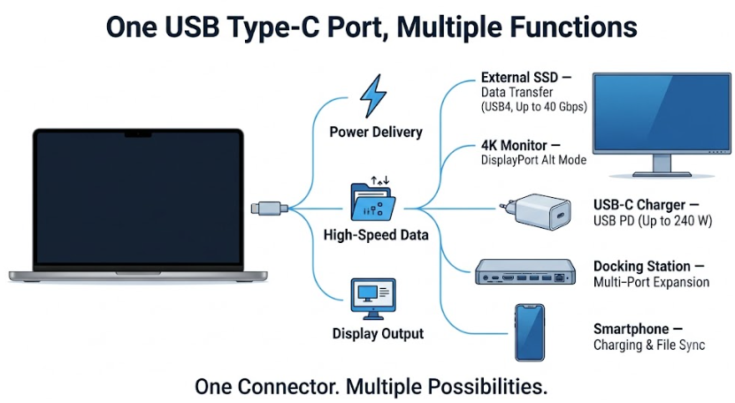
USB-C is often called the “universal connector” because it combines power delivery, data transfer, and video output into a single interface. But behind this “universal” label lies a sophisticated technical ecosystem—from CC pin connection detection, to USB PD power negotiation, to Alt Mode feature expansion—every piece has its own clever design logic.
We hope this dictionary helps you better understand the terminology and concepts in the world of USB-C. The next time you pick up a USB-C cable, you’ll know just how much technology is packed into that small connector.