
If you’ve ever pried open a phone charger, laptop power adapter, or home appliance circuit board, you’ve probably spotted a few odd-looking capacitors stamped with cryptic labels like X2, Y1, or 275VAC. Some are yellow rectangular blocks, others blue disc-shaped parts. Most people know they’re related to electrical safety, but can’t explain the difference between them, whether they’re interchangeable, or what happens if you remove one. These are the two core safety capacitors in every mains-powered device: X capacitors and Y capacitors.
Critical Safety Pre-Warning
X and Y capacitors connect directly or indirectly to hazardous mains high voltage. If you are disassembling a device for inspection, always unplug it from the wall first, wait a minimum of several minutes, and confirm all high-voltage capacitors have fully discharged before touching any components. Non-professionals should never take live measurements, modify capacitor values, or remove safety-rated components. Safety always comes first.
How Do X and Y Capacitors Work? And Why Can’t I Use a Regular Capacitor?
The Mains Input Is a Harsher Environment Than You Think
A lot of people wonder: “They’re just filter capacitors, right? Why can’t I use a regular high-voltage capacitor?” The short answer is: the mains input environment is far harsher than typical low-voltage circuits. It is constantly exposed to 120V/240V AC mains voltage, plus multi-kilovolt surges from lightning, switching spikes from other grid devices, and voltage fluctuations.
If you use a non-safety-rated regular capacitor across L-N or L/N-PE, you could face extremely dangerous outcomes:
- Dielectric breakdown and short circuit, directly connecting line and neutral and causing smoke, fire, blown fuses, or tripped circuit breakers.
- Insufficient insulation, causing the device chassis or low-voltage output to become live, creating an electric shock risk when touched.
- Non-flame-retardant casing and materials, which can spread fire to the rest of the circuit board if the capacitor fails.
That’s the value of safety capacitors: they don’t just perform a filtering function, they meet safety standards even under abnormal conditions, keeping failure risk within acceptable limits.
How X Capacitors Filter Differential Mode Interference
X capacitors rely on a fundamental property of capacitors: their opposition to current flow (impedance) changes with frequency – higher frequencies see lower impedance, lower frequencies see higher impedance. This is described by the capacitive reactance formula:Xc = 1 / (2πfC)
Where Xc is capacitive reactance (impedance) in ohms, f is signal frequency in hertz, and C is capacitance in farads.
For 50/60Hz mains frequency, X capacitors have a very high impedance, acting like an “almost open” circuit that never shorts line and neutral. For high-frequency interference in the megahertz range and above, however, X capacitors have extremely low impedance, acting like a “fast path” that bypasses high-frequency noise so it doesn’t travel further into the circuit.
In real circuits, X capacitors usually work alongside these components:
- Differential mode inductors
- Leakage inductance of common mode chokes
- MOV (metal oxide varistor) for surge protection
- Fuses or fusible resistors for overcurrent protection
- NTC thermistors for inrush current suppression
One important detail: because X capacitors are connected across L-N, they can hold a residual charge after you unplug the device. For this reason, they are almost always paired with a bleed resistor that discharges the residual voltage within a regulated time limit, preventing electric shock when touching the plug prongs.
How Y Capacitors Filter Common Mode Interference
Common mode interference is characterized by simultaneous high-frequency voltage fluctuations on both line and neutral relative to ground – think of it like the water pressure in two pipes rising and falling in sync. This type of interference can’t be filtered by an X capacitor across the two lines, so Y capacitors connected to ground are used instead.
Y capacitors provide a return path for this high-frequency common mode noise, diverting it locally so it doesn’t radiate out through the power cord or travel to the device’s low-voltage side. But just like X capacitors, Y capacitors are not completely “open” to mains frequency – they just have a very high impedance, so an extremely small amount of current “leaks” through. This is called capacitive leakage current.
Leakage current can be estimated with a simple formula:I ≈ 2πfCU
Where f is grid frequency (50Hz or 60Hz), C is Y capacitor capacitance, and U is the AC voltage across the capacitor.
For example: in a 230VAC 50Hz grid, a single 2.2nF Y capacitor has a theoretical mains-frequency leakage current of roughly 0.16mA. Note that this is only a theoretical estimate for a single capacitor. Real-world touch current depends on Y capacitor wiring, grounding method, overall circuit design, and the test method defined by the relevant safety standard. You cannot judge absolute safety solely from this number, and you should never increase Y capacitor capacity on your own. Y capacitor values in certified products are chosen to balance both EMI filtering performance and mandatory touch/leakage current limits.
This is why Y capacitor capacity is never “bigger is better” – it requires a careful tradeoff between filtering effectiveness and leakage current safety limits.
Why Most Power Supplies Use Both X and Y Capacitors
X capacitors handle differential mode interference (noise between the two lines), while Y capacitors handle common mode interference (noise on both lines relative to ground). They target different types of noise, so working together they fully filter out the various disturbances at the power input to meet EMC (Electromagnetic Compatibility) requirements – meaning the device doesn’t interfere with other equipment, and isn’t easily disrupted by external interference.
A typical power input filter structure looks like this:
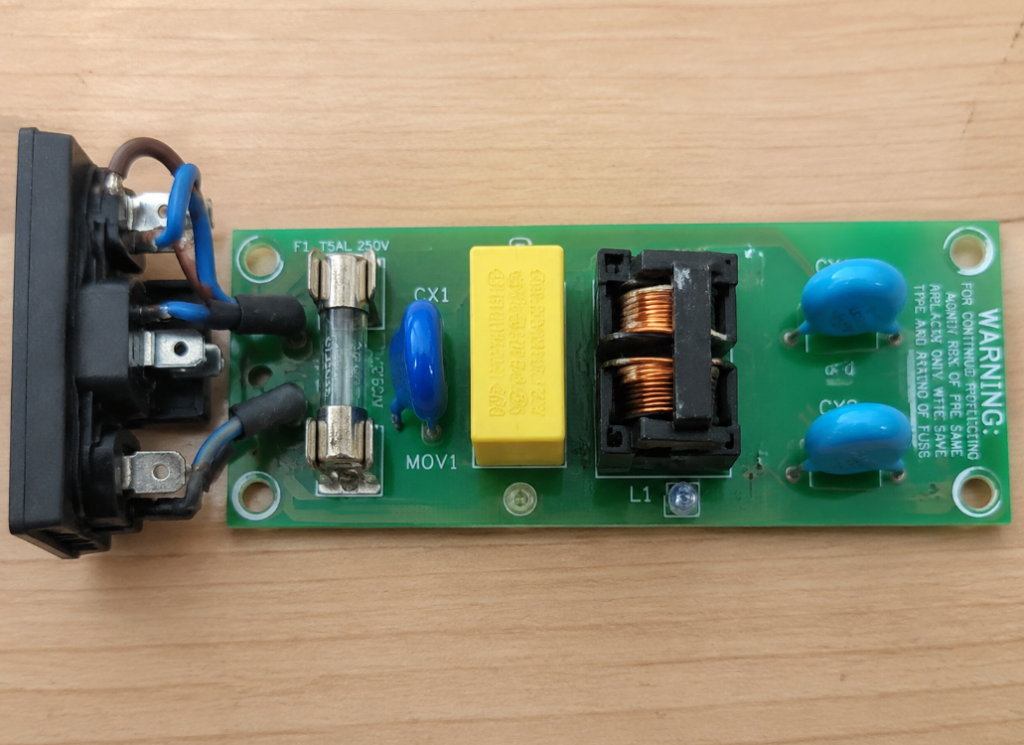
Fuse → MOV Varistor → X Capacitor → Common Mode Choke → Y Capacitors (to PE or across primary-secondary) → Downstream Circuits
If differential mode interference is particularly severe, an additional differential mode inductor may be added.
There are exceptions, of course: very low-power chargers, low-interference products, or extremely cost-sensitive designs may use only X capacitors, only Y capacitors, or even no discrete X/Y capacitors at all. The only requirement is that the product passes EMC testing and safety certification – there is no rule that both must be used.
X Capacitors: Ratings, Label Reading, and Use Boundaries
X1/X2/X3 Rating Differences and Use Cases
X capacitors are used across L-N, so their ratings are defined by their ability to withstand cross-line surge pulses. Per the IEC 60384-14 standard, the three common X ratings are:
- X1: For high-pulse environments, rated for peak pulse voltages >2.5kV and ≤4kV.
- X2: For general mains-powered equipment, rated for peak pulse voltages ≤2.5kV. This is by far the most common X capacitor rating.
- X3: For low-pulse environments, rated for peak pulse voltages ≤1.2kV. Rarely used in consumer electronics.
Selection Rule: X capacitor rating can never be lower than the original design requirement. X1 capacitors can usually be used in X2 positions, but you must still confirm capacitance, size, temperature rating, certification, and cost are appropriate. Never rely solely on the “275VAC” marking – always check the X rating and certification standard.
Note that exact rating values may vary slightly between standard revisions, manufacturer datasheets, and certification bodies. For engineering selection, always refer to the component datasheet and full device certification requirements.
How to Read X Capacitor Labels
X capacitor labels include several core parameters:
- Safety rating: X1, X2, or X3, printed directly on the body.
- Rated AC voltage: Common values include 275VAC, 305VAC, 310VAC, 440VAC, etc. This is the RMS AC voltage rating, not a DC withstand voltage – always check the datasheet to confirm if the part is suitable for DC applications.
- Capacitance: Common values range from tens of nanofarads to ~1µF, with larger values used in high-power or specialized filter designs.
- Tolerance: Common values are ±10% (marked K) and ±20% (marked M).
- Temperature rating: For example, -40~+105°C or -40~+110°C.
- Certification marks: UL, VDE, ENEC, CQC, etc.
Example: A capacitor marked “X2 275VAC 0.1µF K” is an X2-rated safety capacitor with a 275VAC RMS rating, 0.1µF capacitance, and ±10% tolerance.
Common Materials and Structural Features
Most X capacitors are made of metallized polypropylene film. This material has several key advantages for AC cross-line use:
- Excellent AC performance
- Low loss
- High insulation resistance
- Self-healing property: When a small local breakdown occurs, the metallized electrode around the fault point evaporates, isolating the damaged area. The capacitor can continue operating, though capacitance will decrease slightly over time.
X capacitors also use flame-retardant casings and potting materials to meet safety requirements. Note that while many X capacitors are box-shaped, some use specialized packages – shape alone is not a reliable identifier.
Use Boundaries and Common Failures
- Never operate an X capacitor above its rated AC voltage long-term.
- Never replace an X capacitor with a non-safety-rated regular film capacitor.
- Capacitance is not “bigger is better”: Larger values may improve high-frequency bypass, but they also increase reactive current, cost, and size, and can affect surge withstand, discharge time, power factor, and standby power consumption.
Common X capacitor failure modes include:
- Capacitance degradation from aging
- Open circuit or poor pin contact
- Reduced insulation resistance
- Severe failure: short circuit, cracking, smoking, or burning
If an X capacitor shorts, upstream protection (fuse, fusible resistor) should cut off power to prevent further damage. As noted earlier, cross-line X capacitors require a bleed resistor to discharge residual voltage within regulatory time limits after unplugging.
Y Capacitors: Ratings, Label Reading, and Safety Limits
Y1/Y2/Y4 Rating Differences and Use Cases
Because Y capacitors are directly tied to electric shock risk, their safety requirements are usually stricter than X capacitors. Ratings are defined by insulation grade and pulse withstand voltage. The three common Y ratings are:
- Y1: High insulation and pulse requirements, used across reinforced/double insulation boundaries – for example, between the primary (high-voltage) and secondary (low-voltage) sides of an isolated power supply. Important note: A Y1 rating alone does not automatically qualify a capacitor as part of a device’s reinforced insulation system. You must also consider the component’s certified insulation rating, creepage distance, clearance distance, environmental pollution degree, overvoltage category, and the full device’s safety standard.
- Y2: Basic or supplementary insulation grade, commonly used for EMI filtering between L/N and protective earth (the line-to-ground Y capacitors in three-prong devices).
- Y4: For lower rated voltage applications, rarely seen in consumer power supplies.
You may see Y3 referenced in older standards or legacy documentation, but modern mainstream selection focuses on Y1/Y2/Y4. If you encounter a Y3-marked capacitor, always verify its specifications against the relevant certification standard and manufacturer datasheet before using it as a replacement.
Selection Rule: Y capacitor rating can never be lower than the original design requirement. This is especially critical for capacitors used across isolation boundaries, where you must strictly follow the device’s insulation grade and safety standard.
How to Read Y Capacitor Labels
Y capacitor labels follow a similar format to X capacitors, with core parameters including:
- Safety rating: Y1, Y2, or Y4, printed directly on the body.
- Rated AC voltage: Common values include 250VAC, 300VAC, 400VAC, 500VAC, etc., depending on the rating and certification system.
- Capacitance: Common values range from hundreds of picofarads to several nanofarads. Some specialized applications may use values up to ~10nF, but these are not suitable for general replacement.
- Tolerance: Common values are ±10% (K) and ±20% (M).
- Withstand/pulse capability: This cannot be judged from the rated voltage marking alone – always check the datasheet and certification details, as Y capacitor safety depends heavily on pulse withstand and insulation grade.
- Certification marks: Same as X capacitors: UL, CSA, VDE, TÜV, ENEC, CQC, etc. CE alone is not sufficient.
Example: A capacitor marked “Y1 250VAC 222M” is a Y1-rated safety capacitor with a 250VAC rating, 2200pF (22×10² pF) capacitance, and ±20% tolerance.
Why Y Capacitors Are Almost Always Smaller Than X Capacitors
The core reason is leakage current limits. Y capacitors are connected either between protective earth and line/neutral, or across the high-voltage primary and touchable low-voltage secondary sides. The larger the capacitance, the higher the mains-frequency leakage current – and if this exceeds safety limits, it creates an electric shock risk.
Leakage current depends on more than just capacitance:
- Grid voltage: Leakage is higher on 230V grids than 120V grids.
- Grid frequency: Leakage is slightly higher at 60Hz than 50Hz.
- Wiring configuration: Leakage calculations differ for single Y caps, symmetric dual Y caps, and primary-secondary cross-boundary Y caps.
- Device class: Leakage current limits vary by device type. For example, IT equipment, home appliances, and medical devices all have different standards. Class II (two-prong, ungrounded) devices usually have stricter limits than Class I (three-prong, grounded) devices, and medical devices that make direct patient contact have extremely tight limits.
A common misconception is that all devices have a 0.5mA leakage current limit – this is not true. Limits vary widely between product categories, which is why Y capacitor values are always determined by both EMI filtering performance and touch/leakage current testing. You should never increase Y capacitor capacity on your own.
Common Materials and Structural Features
Y capacitors use a wider range of materials than X capacitors, with three common types:
- Ceramic Y capacitors: The most common type, usually the blue disc-shaped parts seen in low-power chargers and adapters. Advantages: small size, low cost. Disadvantages: poorer temperature and voltage characteristics than film capacitors; capacitance changes with temperature and applied voltage.
- Film Y capacitors: Excellent stability and low loss, suitable for high-performance power supplies or filter modules. They are usually larger than ceramic Y caps.
- SMD safety Y capacitors: Used in high-density, miniaturized designs like fast chargers. When using these, you must confirm creepage distance, clearance distance, and certification meet requirements – never rely solely on capacitance and rating.
Regardless of material, all Y capacitors share the same core structural safety requirements: high insulation, flame retardancy, low failure rate, and no dangerous shock path even if they fail.
Typical Wiring and Hard Boundaries
Y capacitor wiring depends on the device’s grounding type:
- Class I (three-prong, grounded) devices: Usually use two symmetric Y capacitors: one from L to PE, one from N to PE. The symmetric design improves common mode filtering performance.
- Class II (two-prong, isolated) adapters: Since there is no protective earth, Y capacitors are connected across the primary-side high-voltage ground and secondary-side low-voltage ground. They may be a single capacitor or multiple capacitors in series/parallel, used to reduce common mode noise. With this wiring, the output side may have a tiny AC induced voltage relative to ground, which can cause a slight tingling sensation when touched. For certified products, this current is always within touch current safety limits.
There are a few things you must never do:
- Never use a regular high-voltage ceramic capacitor across the primary-secondary boundary. Without safety certification, a breakdown will connect high voltage directly to the low-voltage side, which is extremely dangerous.
- Never parallel additional Y capacitors to improve filtering, as this will cause leakage current to exceed safety limits.
- Never replace a Y1-rated capacitor with a Y2-rated one. The lower insulation grade creates a serious safety hazard.
X Capacitors vs Y Capacitors: Key Differences and Quick Identification
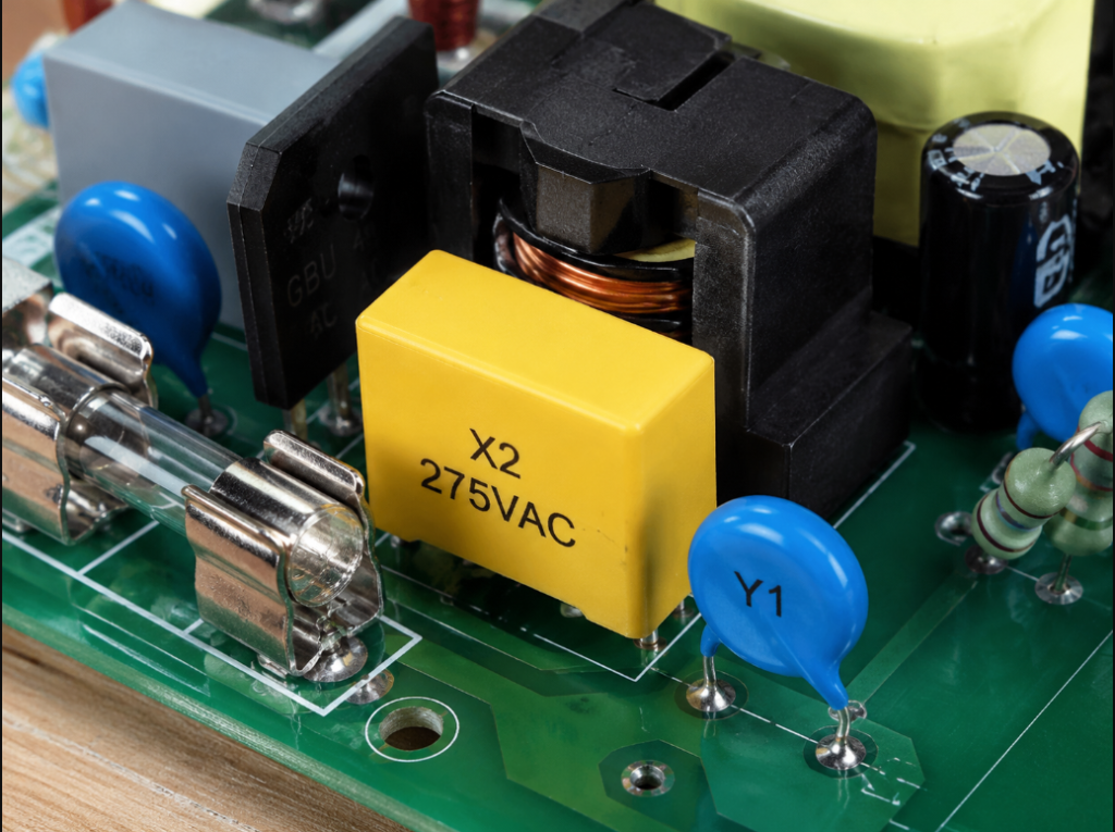
Both are safety capacitors, but they are installed in different positions and serve different safety purposes. X capacitors address cross-line (L-N) failure risks, while Y capacitors address risks related to electric shock, protective earth, chassis, or isolation boundaries.
The table below summarizes the core differences for common mains input filtering and isolated power supply applications:
| Parameter | X Capacitors | Y Capacitors |
|---|---|---|
| Wiring Position | Across line (L) and neutral (N) | Between L/N and protective earth (PE), or across primary-secondary isolation boundary |
| Interference Target | Differential mode interference | Common mode interference |
| Primary Safety Concern | Cross-line surge, short circuit and fire risk | Electric shock risk, insulation grade, leakage current |
| Typical Capacitance Range | Tens of nF to ~1µF (larger for special applications) | Hundreds of pF to several nF (strictly limited by leakage current) |
| Common Appearance | Mostly box-shaped film capacitors | Blue disc ceramic, box-shaped film, or SMD packages |
| Common Ratings | X1, X2, X3 | Y1, Y2, Y4 (most common) |
| Failure Consequence | Short circuit may blow fuses, trip breakers, or cause smoke/fire | Short circuit may create a dangerous electric shock path (stricter safety requirements) |
| Replacement Sensitivity | Capacity can be adjusted within design limits | Capacity is highly sensitive; should match original value as closely as possible |
3-Second Quick Identification Method
- Check the label first: If it’s marked X1/X2/X3, it’s an X capacitor. If it’s marked Y1/Y2/Y4, it’s a Y capacitor.
- Check the wiring: If it’s connected across L and N, it’s almost certainly an X capacitor. If it’s connected from L/N to PE or across the primary-secondary boundary, it’s almost certainly a Y capacitor.
- Check the capacitance: µF-range values are almost always X capacitors; pF/nF-range values are almost always Y capacitors.
- Check the appearance: Box-shaped parts are more commonly X capacitors; blue disc parts are more commonly Y capacitors. Appearance is only a secondary hint, never a final confirmation.
Exceptions to the Rules
- X capacitors may use specialized packages and are not always yellow box-shaped.
- Y capacitors may be square film or SMD parts, not just blue discs.
- Low-power devices may use X capacitors smaller than 0.1µF.
- High-performance filters may use multiple Y capacitors in combination.
- Final identification always relies on rating marks, certification, datasheets, and wiring position.
Practical Pitfall Avoidance: Common Myths, Fault Checking, and Replacement Rules
6 Most Common Misconceptions
Myth 1: You can tell X and Y capacitors apart by color
Fact: There is no global color standard for safety capacitors. Different manufacturers use any color they choose. A blue capacitor might be a regular ceramic part, and a yellow capacitor might be a Y cap. Always rely on rating marks and wiring position.
Myth 2: Bigger Y capacitors are better for filtering
Fact: Larger Y capacitance means higher leakage current, which can exceed touch current safety limits and make the device non-compliant. Y capacitor values are a careful tradeoff between filtering performance and safety – bigger is not better.
Myth 3: A regular capacitor with a high enough voltage rating can replace a safety capacitor
Fact: The core of safety capacitors is their safety certification and fail-safe design, not just voltage rating. Even if a regular capacitor has a high nominal voltage, without safety certification it may short out, catch fire, or cause electric shock if it fails. Never use regular capacitors as replacements.
Myth 4: X1 capacitors have better filtering performance than X2 capacitors
Fact: A higher X rating only means the capacitor can withstand higher surge pulse voltages. It has no direct relation to filtering performance, which depends on capacitance, material, and frequency characteristics. X1 capacitors don’t always have higher capacitance than X2 capacitors.
Myth 5: Y capacitors have zero current if they’re grounded
Fact: Y capacitors have capacitive leakage current at mains frequency – it’s just limited to safe levels. This is especially noticeable in two-prong adapters with no protective earth, where the induced voltage on the output side is a direct result of this leakage current.
Myth 6: Removing Y capacitors fixes tingling sensations with no downsides
Fact: Removing Y capacitors will reduce tingling, but it will cause EMI to exceed limits. This can lead to issues like chargers interfering with phone touchscreens, audio static, or unstable wireless connectivity. It also invalidates the device’s safety certification. Never remove Y capacitors.
Beginner-Friendly Basic Fault Checking
If you suspect a safety capacitor in a power supply has failed, you can perform a few simple preliminary checks – but first, follow these non-negotiable safety rules:
- The device must be completely unplugged from the mains.
- Confirm all large electrolytic capacitors and X capacitors on the board have fully discharged.
- Discharge capacitors using an appropriately rated power resistor. Never short large capacitor leads directly with a wire, as this can destroy the capacitor or damage your multimeter.
The preliminary check steps are simple:
- Visual inspection: If the capacitor has cracks, burn marks, bulging, leaking sealant, corroded pins, or a deformed casing, it is definitely failed and should be replaced immediately.
- Capacitance measurement: Use a multimeter’s capacitance setting or an LCR meter. For the most accurate reading, desolder at least one pin of the capacitor to avoid interference from parallel components on the board. A reading within the marked tolerance (e.g., ±10%, ±20%) is normal. If capacitance is significantly lower than rated, the capacitor has aged and failed.
- Short circuit check: Use a multimeter’s resistance setting to measure across the capacitor leads. A normal capacitor will show a very high resistance that slowly rises to infinity. If the resistance is near 0Ω, the capacitor is shorted and must never be used.
Important note: A regular multimeter only performs low-voltage preliminary checks. It cannot prove the capacitor is safe at high voltages – issues like reduced insulation resistance or high-voltage breakdown cannot be detected with a standard multimeter. Professional safety testing requires specialized equipment to measure insulation resistance, withstand voltage, leakage current, and pulse withstand capability.
Hard Rules for Safety Capacitor Replacement
Whether for repair or prototyping, replacing safety capacitors requires following these strict rules – no cutting corners:
General Rules
- Only use genuine safety capacitors with valid third-party safety certification. Never use regular capacitors as replacements.
- Safety rating can only be equal or higher (never lower). For example, you can use an X1 capacitor in an X2 position, but you cannot use a Y2 capacitor in a Y1 position.
- Rated AC voltage can only be equal or higher (never lower).
- Temperature rating can only be equal or higher (never lower).
- Certification must match the region the device is sold in (e.g., UL for North America, VDE/ENEC for Europe).
- Pin spacing, physical size, creepage distance, and clearance distance must match. This is especially critical for Y capacitors across isolation boundaries: if pin spacing is too small, safety distance requirements are not met, no matter how high the rating.
X Capacitor Replacement Rules
- Never replace an X2 capacitor with a regular film capacitor.
- X1 capacitors can replace X2 capacitors if all other parameters (capacitance, size, temperature, etc.) match, but they are usually more expensive and unnecessary unless the design requires it.
- Keep capacitance as close to the original value as possible. Avoid large changes, as these can affect EMI performance, surge withstand, standby power consumption, and discharge time.
- If you must adjust capacitance, re-evaluate all relevant performance parameters first.
Y Capacitor Replacement Rules
- Never replace a Y1-rated capacitor with a Y2 or lower-rated one.
- Keep capacitance exactly matching the original value if possible. Never change it arbitrarily, as this can cause leakage current to exceed limits.
- Never parallel additional Y capacitors to improve filtering performance.
- For Y capacitors across primary-secondary boundaries, the replacement must meet the required isolation grade – never rely solely on capacitance and voltage rating.
The safest approach for repairs is to replace with the exact same part number, same rating, same capacitance, equal or higher voltage rating, and same certification. This almost guarantees no issues.
Can X Capacitors Be Used for Capacitive Dropper Circuits?
Many people have seen X2 capacitors used in capacitive dropper circuits and assume X capacitors are designed for voltage dropping. While it’s true that X2 metallized film capacitors are commonly used in capacitive droppers because of their good AC performance and safety certification, you cannot just grab any EMI filter X capacitor and use it for voltage dropping. There are critical boundaries:
- You must calculate capacitance accurately based on load current – not just any X2 cap will work.
- You must account for inrush current, and include series current-limiting resistors and fuse protection.
- You must add a parallel bleed resistor to discharge the capacitor when power is removed.
- Capacitive droppers are non-isolated: the output side is directly connected to mains voltage, creating an extremely high electric shock risk.
- The entire circuit must meet full device safety requirements.
Beginner Warning: Do not design or repair non-isolated capacitive dropper circuits on your own. The risk of electric shock is very high for those without professional training.
Typical Parameter Ranges by Application (For Identification Only, Not Design Values)
To help you identify parts on real boards, here are approximate parameter ranges for common power supply types. These are only rule-of-thumb guidelines for identification, and must never be used as design values:
- Phone/tablet low-power chargers (5W~100W): X capacitors may be omitted in very low-power designs. If used, they are almost always X2 275/305VAC, 0.047~0.22µF. Y capacitors across primary-secondary are usually Y1-rated, 470pF~4.7nF.
- Laptop adapters/medium-power SMPS (65W~300W): X capacitors are typically X2 275/305VAC, 0.1~0.47µF. Y capacitors are 1nF~4.7nF, sometimes used in multi-capacitor combinations.
- Desktop PC ATX power supplies (300W~1000W): X capacitors are typically X2 275/305VAC, 0.1~1µF. Y capacitors (L/N to PE or primary-secondary) are usually 1nF~4.7nF, with exact values depending on the schematic for multi-capacitor setups.
- Industrial power supplies/380VAC applications: May require X1 or specialized X2 capacitors with higher rated voltage and surge ratings. Y capacitors must be selected based on system grounding, overvoltage category, pollution degree, and insulation requirements.
Again: these are only identification guidelines. They do not replace original manufacturer design, component datasheets, or certification testing.
Advanced: How X and Y Capacitors Work With EMI Filters
Differential Mode Interference Path and X Capacitors
Differential mode interference flows between line and neutral – noise that travels in on one line and out on the other. X capacitors reduce the high-frequency impedance between L and N, allowing high-frequency differential mode noise to be bypassed directly.
X capacitors usually work with differential mode inductors (or the leakage inductance of a common mode choke) to form an LC low-pass filter that blocks high-frequency interference. Designers must balance capacitance, loss, size, surge withstand, and discharge time – bigger is not always better.
Common Mode Interference Path and Y Capacitors
Common mode interference usually comes from sources like high dv/dt from fast-switching transistors, parasitic capacitance between transformer windings, or coupling capacitance between heat sinks and switching components. This noise appears on both line and neutral simultaneously, oscillating relative to ground.
Y capacitors provide a controlled return path for this common mode current, preventing it from radiating out through the power cord and reducing conducted emissions. They are usually paired with a common mode choke: the choke blocks common mode interference, and the Y capacitor diverts it back. Together they provide much better performance than either component alone.
When designing Y capacitor circuits, engineers must balance EMI margin, touch current limits, insulation grade, and cost. Adjusting Y capacitor values is one of the most common tweaks power supply engineers make during EMI debugging.
Why Some Chargers Cause a Tingling Sensation or Touchscreen Glitches
Almost everyone has encountered this: when charging a phone with a certain two-prong charger, touching the phone’s metal frame feels slightly tingly, or the touchscreen glitches and becomes unresponsive. This is directly related to Y capacitors.
Class II two-prong adapters have no protective earth, so the secondary low-voltage ground is connected to the primary high-voltage ground via a Y capacitor, leaving it floating at an AC potential relative to actual earth ground. The current from this potential is extremely small, and certified products have touch current well within safety limits, so you may only feel a faint tingle occasionally, with no actual danger.
However, if the Y capacitor value is wrong, transformer shielding is poor, or the EMI design is subpar, this induced voltage can become large enough to cause noticeable tingling, interfere with capacitive touchscreens, cause audio static, or disrupt wireless connectivity.
If you feel a sharp stinging sensation when touching a charging device, or your home’s residual current device (RCD/GFCI) trips, stop using the charger immediately. Troubleshoot step by step: check if the adapter is faulty, if the outlet is properly grounded, if the power strip is damaged, if the environment is excessively humid, or if another device is leaking current. Do not continue using a faulty power supply – replace it with a certified unit or have it inspected by a professional.
How to Spot X and Y Capacitors on a Real Power Board
All the theory is great, but how do you quickly find X and Y capacitors when you’re holding a real power supply board?
Identifying Parts in a Typical Three-Prong (Class I) Power Supply
For grounded three-prong power supplies, trace the circuit from the AC input socket inward. The typical component order is: Fuse → NTC Thermistor → MOV Varistor → X Capacitor → Common Mode Choke → Y Capacitors.
- X capacitors are connected across L and N, usually located before or after the common mode choke. They are usually larger and often box-shaped.
- Y capacitors are connected from L to PE and N to PE, usually two identical capacitors arranged symmetrically, with their other pins connected to the protective earth terminal.
Identifying Parts in a Typical Two-Prong (Class II) Isolated Adapter
Two-prong adapters have no PE ground, so their structure is simpler:
- X capacitors may be connected across L-N, or omitted entirely in very low-power designs.
- Y capacitors are usually connected across the primary-side high-voltage ground and secondary-side low-voltage ground, spanning the transformer’s isolation slot. If you see a small capacitor (either a blue disc or small square) mounted or wired across the two sides of the transformer, it is almost certainly a Y capacitor.
Critical note: Any capacitor spanning the primary high-voltage ground and secondary low-voltage ground must be a safety Y capacitor meeting the isolation boundary requirements. In many cases this requires a Y1 rating or a part certified for reinforced insulation. Whether a Y2 rating is acceptable depends on the full device safety standard and manufacturer datasheet – never judge by appearance or capacitance alone, and never use a regular capacitor as a replacement.
Safety Rules for Working on Power Boards
Finally, a few non-negotiable safety rules for inspecting and debugging power boards:
- Never touch the primary-side high-voltage area with your hands, even after power is off – always confirm capacitors are fully discharged first.
- Never short the grounds on either side of the isolation slot with a wire. This breaks the insulation barrier and creates a serious electric shock risk.
- Never operate a power supply long-term with Y capacitors removed. Not only will it fail EMI requirements, it is also a safety hazard.
- Never connect a regular oscilloscope’s ground clip directly to the primary-side hot ground. This will short the oscilloscope’s ground, destroy equipment, and potentially cause electric shock. Only use an isolation transformer or differential probe, and only if you have the professional training to do so safely.
Final Summary
By now you should have a comprehensive understanding of X and Y capacitors. Test your knowledge with this quick checklist:
- ✅ You can identify them by wiring position: X caps across L-N, Y caps from L/N to PE or across primary-secondary.
- ✅ You understand their different functions: X suppresses differential mode interference, Y suppresses common mode interference.
- ✅ You can read basic labels: X1/X2, Y1/Y2, VAC, capacitance, tolerance, and certification marks.
- ✅ You know why Y capacitors can’t be arbitrarily increased: leakage/touch current is limited by safety standards.
- ✅ You can avoid common myths: no color-based identification, no regular capacitor replacements, no blind capacity increases, no arbitrary Y capacitor removal.
- ✅ You can perform safe replacements: same or higher rating, same or near-original capacitance, equal or higher voltage, matching certification, correct size and spacing.
- ✅ You can do basic fault checks: visual inspection, capacitance measurement, short circuit check – and you know a multimeter can’t prove high-voltage safety.
- ✅ You understand the boundaries: real designs must pass EMC testing, safety testing, and be validated with manufacturer datasheets. You can’t modify parts based on guesswork.
X and Y capacitors may look like small, unremarkable components, but they are absolutely core to power supply safety and electromagnetic compatibility. Whether you’re a repair hobbyist or a beginner power supply designer, always put safety first, follow standards and datasheets strictly, and never cut corners on safety components – after all, safety capacitors are the last line of defense against electrical hazards.