
1.Electrical Isolation Distances Explained: Clearance, Creepage Distance, and Low/High-Voltage Safety Rules Demystified
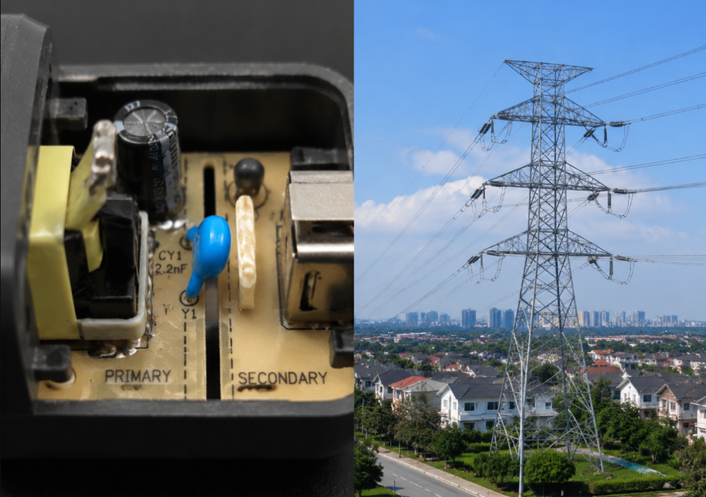
When we use electricity every day, we rarely think about its “invisible safety boundaries.” You can’t see or feel them, but they directly determine whether you’ll get shocked or whether an electrical fire will start. From the tiny circuit boards inside phone chargers to 100-foot-tall high-voltage transmission lines, every energized device and circuit relies on a set of unseen isolation rules to keep dangerous voltage contained where it belongs.
Important preface: This article is for general educational awareness and preliminary self-checks only. For formal electrical design, installation, inspection, or commissioning, always follow current IEC, UL, NEC, local regulatory codes, and product-specific standards. Do not rely solely on general rule-of-thumb values for safety-critical decisions.
2. What Determines Required Isolation Distances?
Many people assume isolation distances are fixed — for example, that 230V always requires a specific number of millimeters. That is not true. Required distances depend on multiple factors, and even at the same voltage, requirements can be several times higher or lower depending on the environment and materials used.
2.1 Voltage Parameters: The Most Critical Factor
Voltage is the single biggest driver of isolation distance requirements: higher voltage almost always requires larger distances. But “voltage” here does not just mean steady operating voltage — you have to account for multiple voltage conditions.
2.1.1 Operating voltage and voltage class
The industry generally defines low-voltage (LV) systems as those below 1000V AC or 1500V DC — the systems used in most homes and offices. Systems above this threshold are classified as high-voltage (HV), such as outdoor transmission lines and industrial high-voltage equipment. High voltage is further divided into classes like 3kV, 6kV, 10kV, 35kV, 110kV, and higher, with stricter isolation requirements for higher classes.
2.1.2 Rated impulse voltage and Overvoltage Category (OVC)
In addition to steady operating voltage, circuits can experience sudden “surge voltages” — for example, from lightning induction, circuit breaker operation, or large motor startup — where voltage spikes far above normal levels. These impulse voltages are a common cause of air breakdown and insulation failure.
IEC standards use Overvoltage Categories (OVC) to classify surge risk across different scenarios, from lowest to highest:
- OVC I: Internal circuits of heavily protected electronic devices, such as small components on a phone motherboard. Surges are filtered out by upstream protection circuits, so risk is minimal.
- OVC II: Household appliances and portable devices powered by wall outlets, such as TVs and laptops. Surge risk is moderate.
- OVC III: Distribution panels, permanently installed industrial equipment, and lighting circuits. Surge levels here are higher than at household outlets, so risk is greater.
- OVC IV: Outdoor service entrances, main distribution boards, and exterior supply points that connect directly to the utility grid. Surge risk is highest.
The higher the overvoltage category, the larger the required clearance.
2.1.3 Differences between AC, DC, and high-frequency systems
Many people assume that if the voltage number is the same, isolation requirements are the same. That is not the case. For example, DC arcs are harder to extinguish than AC arcs at the same voltage level, so requirements may differ. High-frequency circuits (such as the tens of kHz to MHz signals in switch-mode power supplies) have additional concerns like dielectric loss, parasitic capacitance, and electromagnetic compatibility (EMC) interference, so you cannot directly apply 50/60Hz AC distance rules. Required adjustments must be based on relevant product standards and test requirements, not rough percentage estimates.
2.2 Environmental Conditions: Pollution, Humidity, and Altitude Change Requirements
Even with identical voltage and equipment, isolation distance requirements can vary dramatically based on the environment.
2.2.1 Altitude
The higher the altitude, the thinner the air, and the lower its insulating ability — much like how water boils at a lower temperature at high elevations. The breakdown voltage of air decreases as altitude increases, so electrical equipment used at high altitudes requires larger clearances than equipment used at sea level. Most standards include specific altitude correction factors for this purpose.
2.2.2 Temperature, humidity, and contaminants
If an environment is humid, prone to condensation, or has salt spray, oil, or dust, the surface conductivity of insulation increases significantly, raising creepage risk. In these cases, creepage distance must be increased.
2.2.3 Pollution Degrees (PD 1–4)
To standardize environmental contamination levels, IEC standards define four Pollution Degrees, from mild to severe:
- PD1: Fully sealed, clean environments with no conductive contamination, such as the inside of hermetically sealed electronic components. Virtually no pollution.
- PD2: Normal indoor environments with only occasional non-conductive contamination, such as residential bedrooms and offices. This is the most common scenario.
- PD3: Industrial workshops, kitchens, and semi-outdoor areas where conductive contamination or condensation may occur. Higher risk.
- PD4: The harshest environments, such as areas with persistent conductive dust, rain/snow, or chemical corrosion. Conductive paths form very easily on insulation surfaces.
The higher the pollution degree, the larger the required creepage distance.
2.2.4 Special environments
For special environments like corrosive, explosive, mining, marine, or extreme high-temperature/high-humidity settings, dedicated specialized standards must be used. Simply scaling up standard distances is not sufficient and can lead to serious accidents.
2.3 Insulation Materials and CTI Rating
The type of insulation material used also directly affects required isolation distances.
2.3.1 Air insulation
Air insulation is the lowest-cost and most widely used type, but it has significant drawbacks: its performance is highly variable depending on altitude, humidity, pollution, and electrode shape, so insulating properties are inconsistent.
2.3.2 Solid insulation
Solid insulation (such as plastic, ceramic, epoxy) is the most common form of insulation inside equipment. A key metric here is the Comparative Tracking Index (CTI), which measures a material’s resistance to surface breakdown from electrical arcing (a process called “tracking”). A higher CTI means the material’s surface is less likely to develop permanent conductive paths from electrical stress. In standards, CTI is the core basis for grouping insulating materials. Under identical operating voltage, pollution degree, insulation type, and where allowed by applicable standards, higher CTI materials may allow smaller creepage distance requirements — but using a higher CTI material does not automatically mean you can reduce isolation distances.
2.3.3 Liquid and gas insulation
There are also liquid and gas insulation types, such as transformer oil, SF₆ gas used in high-voltage switchgear, and vacuum insulation. These are generally used in medium- and high-voltage equipment. Their insulating ability is not fixed: it depends on medium pressure, purity, equipment geometry, electric field uniformity, and relevant test standards, so you cannot simply convert them using air insulation ratios.
2.4 The Role of Enclosures, IP Ratings, and Barriers
A common myth is that if a device has a high IP-rated enclosure, you do not need to worry about internal isolation distances. That is a mistake.
2.4.1 What IP ratings do (and don’t do)
IP (Ingress Protection) ratings (like IP20 or IP67) are designed to limit access by fingers, tools, dust, and water to the inside of equipment, reducing the risk of direct contact with live parts. But they cannot arbitrarily replace internal clearance, creepage distance, and voltage withstand requirements. For example: even if an enclosure blocks fingers from reaching inside, if two internal live parts are too close together, they can still arc over, burn through the enclosure, and start a fire.
2.4.2 Barriers, enclosures, and accessibility
That said, barriers and insulated enclosures do reduce the risk of direct human contact — if live parts are completely inaccessible, direct shock risk is much lower. But this is only external protection; internal insulation coordination must still meet relevant product standard requirements. You cannot reduce internal isolation distances just because there is an outer enclosure.
3. Authoritative References: Common Standards and Typical Distance Values
With all these factors in play, where do actual isolation distance values come from, and what standards can you reference? First, a critical note: final compliance determinations for isolation distances must be based on applicable general standards, product-specific standards, local regulations, and official test results. Industry rule-of-thumb values, internal company guidelines, or technical handbooks are only for preliminary estimation and risk screening — they cannot replace formal compliant design and acceptance testing.
3.1 Overview of Major Safety Standards
Global electrical safety standards fall into three broad categories:
- International standards: The foundational standard for low-voltage insulation coordination (how to select isolation distances) is IEC 60664. Other key international standards include IEC 60364 (Low-voltage electrical installations), IEC 61140 (Protection against electric shock), and for high-voltage systems, IEC 60071 (High-voltage insulation coordination). These standards form the basis for national standards in most countries around the world.
- Regional and national standards: Different countries and regions adapt standards to their own needs. Examples include China’s GB/GB/T series (many of which are identical to IEC standards), the European Union’s EN series, the United States’ UL standards and NEC (National Electrical Code), and Australia/New Zealand’s AS/NZS series. Products sold or projects built in a given region must meet local mandatory standards.
- Product-specific standards: Beyond general standards, different product categories have more detailed requirements. Information technology equipment, household appliances, lighting, medical devices, industrial control equipment, and EV chargers all have dedicated safety standards, whose isolation distance requirements may be more specific and stricter than general standards. Product-specific standards always take precedence in real-world applications.
3.2 Low-Voltage Equipment: How to Look Up Clearance and Creepage Distance
Low-voltage equipment isolation distances are not arbitrary — they follow a strict lookup logic, with different parameters corresponding to different values.
3.2.1 Clearance lookup logic
The lookup sequence for clearance is: first confirm operating voltage, then determine rated impulse voltage based on Overvoltage Category, then factor in pollution degree, and finally apply altitude correction to get the minimum required clearance. Because clearance is driven primarily by rated impulse voltage and air breakdown risk, Overvoltage Category and altitude correction have a particularly large impact on the final value.
3.2.2 Creepage distance lookup logic
The lookup sequence for creepage distance is: first confirm operating voltage, then factor in pollution degree, then reference the insulation material’s CTI group, and finally specify the insulation type (basic, supplementary, or reinforced) to calculate the minimum required creepage distance. Creepage distance is mainly affected by operating voltage, pollution degree, material group/CTI, and insulation type. Different insulation types have completely different requirements; reinforced insulation almost always has stricter requirements, so you cannot use the same values for all insulation types.
3.2.3 Reference values for 120V/240V household devices
For typical appliances powered by a standard wall outlet, under OVC II, Pollution Degree 2, and basic insulation, clearance and creepage distances are generally in the single-digit millimeter range. But this is only a very rough estimate — exact values must be confirmed against IEC 60664 and relevant product standards. Never use these rough numbers to modify equipment on your own.
3.2.4 Key takeaway for non-professionals
For non-professionals, the core rule to remember is this: exposed 120V/240V/380V live parts must never be accessible. “Staying far away” is never a substitute for actual safety measures like de-energization, guarding, insulation, grounding, and residual current protection.
3.3 High-Voltage Lines and Equipment: Common Safety Distance References
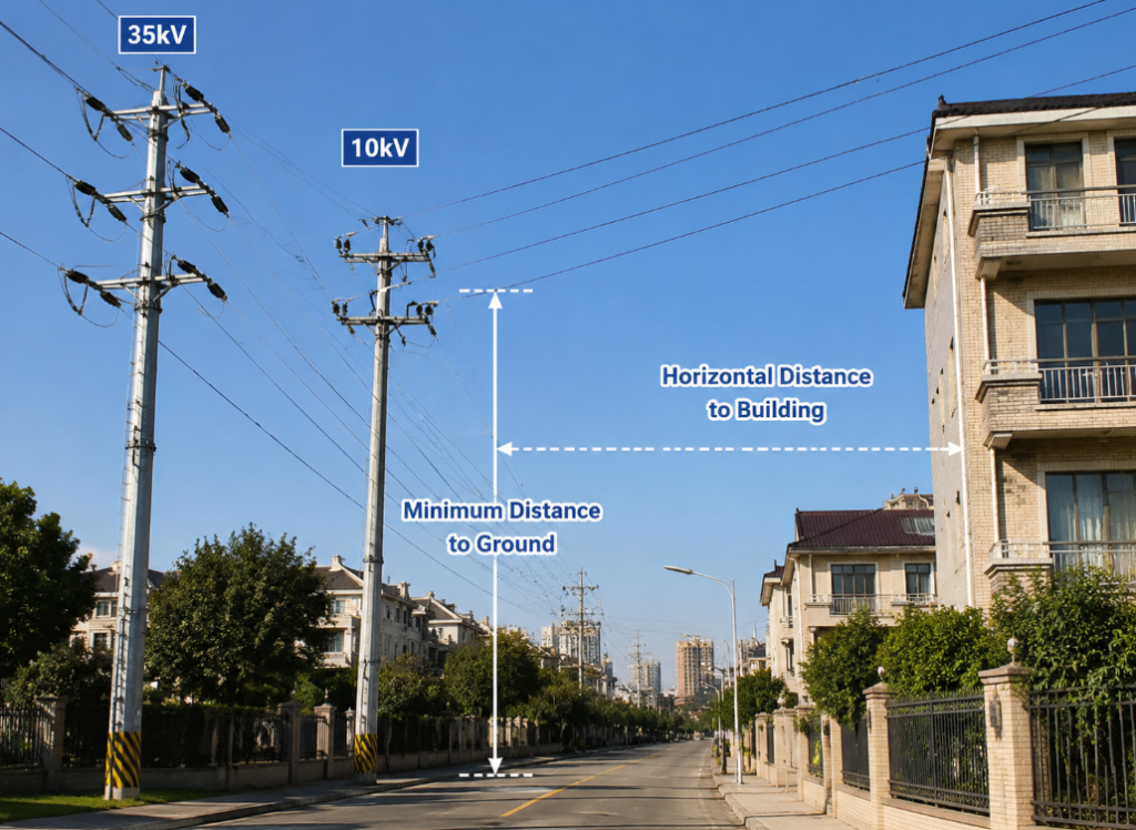
High-voltage safety distances are far more complex than low-voltage ones, with many more influencing factors. The values below are general educational references for bare overhead lines in residential areas, based on common national design codes. Actual values depend on local regulations, line design standards, conductor sag, wind deflection, operating temperature, what the line crosses (roads/railways/water), conductor type (bare/insulated), and local terrain. These values do not apply to live work, crane operation near lines, or special crossing scenarios. Always defer to local power authorities and current codes for formal requirements.
| Voltage Class | Minimum Clearance to Ground (Residential Areas, Reference) | Minimum Horizontal Clearance to Buildings (Reference) |
|---|---|---|
| 10kV | 6.5m (21.3ft) | 1.5m (4.9ft) |
| 35kV | 7.0m (23.0ft) | 3.0m (9.8ft) |
| 110kV | 7.5m (24.6ft) | 4.0m (13.1ft) |
For personal safety when working near high-voltage equipment, common reference distances are 0.7m (2.3ft) or more for 10kV, and 1.0m (3.3ft) or more for 35kV.
Again, these are only general references. If you are working, lifting materials, fishing, flying kites, or carrying long metal poles near high-voltage lines, you must strictly follow local power authority rules and on-site safety requirements. Never estimate distances by eye and risk getting close.
4. How to Verify Isolation Distance Compliance
Now that you understand the standards and reference values, how do you actually check if isolation distances are acceptable in real life? We can break this into two approaches: quick self-checks for non-professionals, and systematic verification for qualified electrical personnel.
4.1 Core Assessment Logic
Whether for low or high voltage, the core logic for judging isolation distance compliance is the same: you cannot just look at voltage. You first need to confirm the voltage class and system type, then factor in environmental pollution degree, overvoltage category, insulation materials, altitude, and the relevant product or project standard. You cannot get an accurate result if any of these parameters are missing.
4.2 Non-Professional 3-Step Quick Check
If you are not a trained electrician, you do not need to dig through complex standard tables. Following these three steps will help you avoid most risks:
4.2.1 Step 1: Assess the environment
Requirements vary drastically by setting. A dry bedroom has very different insulation requirements than a humid bathroom, a greasy kitchen, an outdoor space, a high-altitude location, or an industrial workshop. The harsher the environment, the higher the required protection rating for equipment. For example, in bathrooms, kitchens, outdoor areas, and other wet or water-exposed spaces, you must follow local electrical codes for installation location, IP rating, splash protection, RCD/GFCI protection, and equipotential bonding. Never use standard indoor-only outlets in wet or water-exposed areas.
4.2.2 Step 2: Check certification and product source
For household electrical products, prioritize reputable products that meet local market access requirements:
- In China, look for the CCC (China Compulsory Certification) mark for applicable products.
- In the EU, the CE mark is generally a manufacturer’s self-declaration of compliance with relevant directives, not equivalent to third-party testing and certification for most product categories.
- In the US, distinguish between UL Listed (for end products) and UL Recognized (for components), and confirm that the standard number and product model on the mark match the product.
Certification is an important safety reference, but you also need to verify that the certification is legitimate, the model matches, and the product is used in the correct environment. For example, using an indoor-only outlet outdoors in the rain is unsafe even if it has a certification mark.
4.2.3 Step 3: Watch for warning signs
If you feel a tingle when using an appliance, hear buzzing or arcing, smell burning plastic, notice unusual heat, feel loose plugs, see cracked enclosures, or find signs of water damage, the insulation or isolation is likely compromised. Stop using the device immediately and have it inspected by a qualified professional — never keep using a faulty appliance.
4.3 Professional Verification: Low-Voltage Checks per IEC 60664
For professionals performing low-voltage equipment insulation verification, the core is the parameter chain defined in IEC 60664: operating voltage, rated impulse voltage, Overvoltage Category, Pollution Degree, material CTI group, insulation type (basic/supplementary/double/reinforced), and altitude correction. All parameters are required — you cannot calculate accurately if any are missing.
In addition to dimensional calculations, verification requires testing:
- Dielectric withstand (hipot) testing: Applying a specified high voltage to insulation to check for breakdown.
- Insulation resistance testing: Measuring the resistance of insulation to confirm it is sufficiently high.
- Leakage current testing: Verifying that leakage current during normal operation is within safe limits.
- Temperature rise and aging testing: Confirming that insulation does not fail from heat or aging over long-term use.
4.4 High-Voltage Assessment Principles
High-voltage isolation distance assessment is far more complex than low-voltage, and cannot be estimated with simple linear formulas. High-voltage air gap requirements depend on voltage class, insulation medium type, electrode shape (breakdown voltage varies significantly between sharp and rounded electrodes), altitude, pollution class, lightning and switching overvoltage levels, and relevant equipment standards. Non-professionals should never estimate distances and proceed with construction — all high-voltage work must be designed and verified by qualified professionals in accordance with codes.
4.5 How to Measure Isolation Distances
If you need to physically measure isolation distances, the method varies by metric:
- Clearance measurement: For simple flat structures, you can measure directly with calipers or feeler gauges. For complex 3D structures, use 3D measurement equipment or calculate from structural drawings. The key is to find the shortest air path between two live parts, or between a live part and an accessible conductive part.
- Creepage distance measurement: The key is to find the shortest conductive path along the insulation surface, accounting for the actual path contaminants would take. When encountering grooves, holes, or raised features, whether you trace along the edge (and count that length toward the total) depends on the applicable standard’s rules for groove width, depth, and opening shape. You cannot just assume every groove adds creepage distance — for example, very narrow, shallow grooves can be bridged directly by contaminants, so their edge length is not counted.
- Full equipment insulation verification: Size measurements alone are not sufficient. Only a qualified laboratory performing a full set of electrical tests per relevant standards can make a final compliance determination.
5. Common Scenarios and Pitfalls to Avoid
All that theory is useful, but let’s apply it to the most common real-world scenarios, with key pitfalls to avoid.
5.1 Household Low-Voltage Scenarios
Home electrical systems seem simple, but many accidents stem from small details.
5.1.1 Distribution panels (breaker boxes)
Many people modify their breaker boxes during renovations, leaving wires jumbled, copper bus bars exposed, and phase, neutral, and ground wires arranged haphazardly. This can easily lead to insufficient phase-to-phase or phase-to-ground isolation, causing arcing or even fires. Always have a licensed electrician modify or repair your distribution panel. Wires must be arranged per code, exposed live parts must have reliable guarding, and non-professionals should never open the inside of a distribution panel.
5.1.2 Outlets and switches
Cheap, low-quality outlets are a hidden hazard in many homes. Common issues include thin copper contacts with poor grip, non-flame-retardant recycled plastic housings, and insufficient internal isolation between live parts. Over time, dust and moisture build up, leading to leakage or even fire. Do not buy no-name outlets from untrusted sources — always choose reputable brands with proper local certification.
5.1.3 High-power appliances
Electric water heaters, air conditioners, ovens, induction cooktops, and other high-power appliances draw large currents, so their insulation and isolation requirements are higher. Always use a properly rated dedicated outlet, ensure reliable grounding, install a residual current device (RCD, called GFCI in North America), and add splash protection for outlets in wet areas per local codes.
5.2 Consumer Electronics
The phones, laptops, and appliances we use every day also rely on proper isolation distances.
5.2.1 Phone and laptop chargers
In a legitimate power adapter, the mains side (primary, connected to the wall outlet) and the low-voltage side (secondary, connected to your phone) must meet reinforced insulation or equivalent protection requirements. If insulation fails, 120V/230V mains voltage can leak to the low-voltage side, shocking anyone touching the phone. Cheap counterfeit chargers cut costs by shrinking the isolation gap between primary and secondary sides, or using low-quality insulation materials, making them extremely dangerous.
5.2.2 Appliance control boards
The control panels on refrigerators, washing machines, and other appliances have buttons, knobs, and displays — all low-voltage parts that people touch. There must be sufficient isolation between these accessible low-voltage parts and the high-voltage circuits behind them. In cheap, poorly made products, insufficient isolation can allow high voltage to reach the control panel via creepage or arcing, causing a shock when you press a button.
5.3 Outdoor Public Scenarios
Outdoor electrical environments are more complex and carry higher risk.
5.3.1 Near high-voltage lines
Every year, people are shocked while fishing, flying kites, or working under high-voltage lines. Many people think “I’m far enough away,” but high-voltage safety distances depend on voltage class, weather, conductor condition, and other factors that you cannot judge accurately by eye. Never fish, fly kites, carry long metal poles, or perform lifting/construction work under high-voltage lines. If you need to work near lines, contact your local power authority first for on-site assessment and guidance from qualified personnel.
5.3.2 Outdoor EV chargers
As electric vehicles become more common, outdoor public chargers are widespread. Legitimate chargers have insulation monitoring, ground fault detection, leakage protection, and weatherproof enclosures, so they are safe for normal use. But be careful in the rain: if the charger is damaged, there is standing water around it, or your hands are wet, do not plug or unplug the connector to avoid accidental shock.
5.4 Industrial Electrical Scenarios
Industrial environments have higher voltages and more complex conditions, so isolation distance requirements are stricter.
5.4.1 Control cabinet bus bars and terminals
Industrial control cabinets have copper bus bars and terminal blocks. You need to pay special attention to phase-to-phase distances, phase-to-ground distances, cable end termination quality, burrs on copper bar edges, and distances to cabinet doors and metal brackets. Insufficient distances can easily cause breakdown and short circuits, leading to serious equipment damage or even fires.
5.4.2 VFDs and servo drives
Variable frequency drives (VFDs) and servo drives are common industrial devices with both high-voltage and low-voltage circuits, plus high-frequency switching signals. So in addition to basic high/low voltage isolation distances, you also need to account for EMC spacing, grounding, shielding, and heat dissipation. If these are ignored, you will either have insulation failures or electromagnetic interference that disrupts nearby equipment.
6. Common Misconceptions and Everyday Safety Tips
Many people have misunderstandings about electrical isolation distances that can put them at risk. Here are the most common misconceptions, plus safety tips everyone should know.
6.1 4 Widespread Misconceptions
6.1.1 Misconception 1: Insulation removes the need for isolation distances
Many people think that if wires have a plastic jacket or live parts are wrapped in insulation, you do not need to leave gaps. But insulation degrades with age, wears away, absorbs moisture, and can be cut by sharp edges. Even with insulation, you still need to meet structural distance and voltage withstand requirements — you cannot rely solely on a thin layer of plastic.
6.1.2 Misconception 2: Bigger distances are always safer
That is not true either. Excessively large distances make equipment bigger, complicate wiring, and drive up costs. The right approach is to design to meet standard requirements, adjusted for the actual environment and verified by testing — bigger is not always better.
6.1.3 Misconception 3: Same voltage = same distance for AC and DC
As we covered earlier, DC arcs are harder to extinguish, and high-frequency/pulsed voltages have parasitic capacitance and dielectric loss concerns. So even if the nominal voltage is the same, isolation requirements for DC, high-frequency, and pulsed systems can differ from 50/60Hz AC. Always calculate per relevant standards.
6.1.4 Misconception 4: RCDs/GFCI make isolation distances unnecessary
Many people think that if a residual current device is installed, it will just trip if there is leakage, so it is fine. But RCDs are a backup measure that activates after a fault occurs, while isolation distances are a preventive measure that stops faults from happening in the first place. They complement each other, and neither can replace the other. If isolation distances are insufficient and arcing/leakage happens frequently, even if the RCD trips, there is still a high fire risk. Plus, RCDs themselves can fail.
6.2 Everyday Safety Tips Everyone Should Follow
Whether you know anything about electrical systems or not, following these rules will help you avoid most electrical risks:
- Always de-energize, test for voltage, and lock out/tag out before doing any home wiring or repairs. Non-professionals should never work inside a distribution panel.
- In wet areas like bathrooms and balconies, use appropriate protective measures per local codes, including splash-resistant enclosures, equipotential bonding, and properly rated GFCI/RCD protection.
- Do not buy outlets, chargers, or electrical products that have no certification, no manufacturer information, or no specifications listed. Do not risk your safety to save a few dollars.
- Non-professionals should never take apart power supplies, chargers, distribution panels, or other energized equipment. Even if you unplug the device, internal high-voltage capacitors can hold a dangerous charge for a long time. If a device needs repair, take it to a qualified professional who can use proper discharge tools and test equipment to confirm it is fully de-energized before working on it.
7. Frequently Asked Questions
Q: What’s the relationship between electrical isolation distance, clearance, and creepage distance?
A: Electrical isolation distance is an umbrella term for all dimensional requirements needed to achieve proper electrical isolation. The two most core metrics are clearance and creepage distance. To put it simply: clearance is the shortest straight-line path electricity can jump through air, while creepage distance is the shortest path along the surface of insulation. Combined with solid insulation thickness, enclosure protection, grounding, and protective devices, these make up a complete electrical isolation system.
Q: What are the minimum clearance and creepage distance for 120V/240V household circuits?
A: There is no single fixed number — it depends on the specific scenario. For typical wall-powered household appliances, under OVC II, Pollution Degree 2, and basic insulation, clearance and creepage distances are generally in the single-digit millimeter range. But exact values must be confirmed against IEC 60664 and relevant product standards, so never use rough estimates to modify equipment on your own. For non-professionals, the only rule you need to remember is: exposed 120V/240V live parts must never be accessible.
Q: Why do you need larger clearances at high altitudes?
A: Because air gets thinner at higher altitudes, so its insulating ability decreases. An air gap that will not break down at sea level may break down at high altitude under the same voltage. Larger clearances compensate for this reduced air insulation performance. All major standards include altitude correction factors: the higher the altitude, the larger the corrected required distance.
Q: Can wrapping bare wires with electrical tape replace proper isolation distances?
A: No. Electrical tape is only intended for temporary insulation repairs. Its voltage withstand, abrasion resistance, heat resistance, and aging performance are far inferior to formal insulation structures, and it will peel or degrade over time. For permanent exposed live parts, you must use proper insulating sleeves, guards, or enclosures, and meet relevant isolation distance requirements. Wrapping with electrical tape alone is not a sufficient long-term solution.
Q: What standards define safety distances for 10kV and 35kV high-voltage lines?
A: Standards vary by region. Internationally, IEC has relevant standards; in China, codes like the Code for Design of 66kV and Below Overhead Power Lines apply; in the US, the NESC (National Electrical Safety Code) applies; and in the EU, EN series standards apply. Safety distances also fall into different categories: clearance to ground, clearance to buildings, work safety distances, and more. They also depend on conductor sag, wind deflection, altitude, and pollution class, so there is no one-size-fits-all number. Always defer to local power authorities and current codes.
Q: How do isolation requirements differ for high-frequency circuits/switch-mode power supplies vs. line-frequency circuits?
A: Line-frequency circuits (the 50/60Hz AC power we use in homes) mainly require isolation for line-frequency voltage withstand and surge breakdown. High-frequency circuits (like the tens of kHz to MHz signals in switch-mode power supplies) have an additional concern: parasitic capacitance coupling. Even if clearance and creepage distance are sufficient, high-frequency signals can couple through parasitic capacitance to the low-voltage side, creating safety risks or electromagnetic interference. High frequency also increases dielectric loss in insulation materials, causing more heat and accelerating aging. So high-frequency circuit isolation requires addressing parasitic capacitance, EMC, and dielectric loss in addition to basic distance requirements, making it more complex.
Q: How can I tell if a charger has reliable high/low voltage isolation?
A: For non-professionals, the simplest method is to buy reputable products that meet local market access requirements. In the US, look for UL Listed chargers; in the EU, note that CE marking is generally a manufacturer self-declaration; in China, look for CCC certification. Avoid no-name products priced far below market rate. Products from legitimate channels that meet access requirements almost always meet basic high/low voltage isolation standards. For professional verification, you would need to disassemble the charger to check the gap between primary and secondary sides and insulation materials, plus perform hipot and insulation resistance tests to confirm it meets reinforced insulation requirements.
Conclusion: The Invisible Distances That Underpin Electrical Safety
Electrical isolation distances are never a single number — they are a complete safety system determined by voltage, environment, materials, structure, and testing. From the outlets in your home and the phone charger in your pocket to high-voltage transmission lines outside, truly reliable electrical safety never comes from luck or “being careful.” It comes from compliant design, code-compliant installation, regular inspections, and careful use by everyone.
These invisible distances — a few millimeters inside a charger, a few meters under a power line — are the first and most important line of defense protecting us from electrical harm.