
In precision manufacturing, electronic assembly, printing and packaging, alignment deviation is a critical factor that determines product functionality, appearance and long-term reliability. In practice, the term is often confused with related concepts such as position tolerance, positioning error and assembly error. There are also widespread inconsistencies in test method selection, acceptance criteria setup and data application.
This article systematically covers the core requirements of alignment deviation testing, from basic definitions and measurement principles to equipment selection, process control, error analysis and closed-loop production management. It serves as a reference for quality, process, R&D and testing professionals.
Disclaimer: The term “alignment deviation” used in this article is a general engineering designation. Specific calculation methods, acceptance limits and judgment rules shall always follow product drawings, Geometric Dimensioning and Tolerancing (GD&T) specifications, tolerance requirements, process documents and customer agreements.
1. What Is Alignment Deviation
1.1 Core Definition
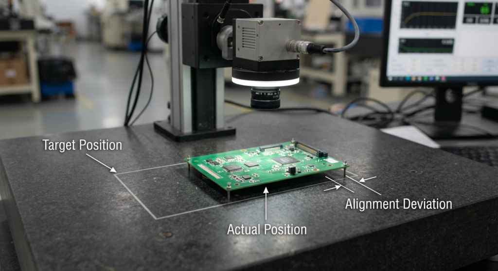
Alignment deviation is a general engineering term referring to the difference between the actual relative position and the required position of two or more objects, based on a defined datum, theoretical position or specified alignment relationship. It covers multiple forms including translation, rotation and deformation.
Alignment deviation testing is the process of establishing a unified datum and coordinate system, collecting position data of reference features and target features, calculating offset values according to an agreed model, and comparing the results against tolerances or judgment rules.
In English technical documentation, the most commonly used equivalent term is alignment deviation, and its exact meaning shall be interpreted according to the industry context and application scenario.
1.2 Distinction from Related Concepts
As a general term, alignment deviation is related to but distinct from various position-related concepts in different fields:
- Position tolerance: A formal geometric tolerance item in GD&T, evaluated against theoretically exact positions, an applicable datum reference frame and tolerance zones. Its calculation strictly follows specifications such as ISO 1101 and ASME Y14.5. It is one of the standardized metrics that can be used for alignment deviation evaluation.
- Positioning error: Usually refers to the offset of a single object relative to its target position. Its definition varies by industry and scenario with no unified calculation rule, and can be regarded as a single-dimensional manifestation of alignment deviation.
- Assembly error: A broader concept that may include multi-dimensional deviations in position, orientation, clearance, deformation and accumulated tolerance, and is not limited to the alignment dimension. Alignment deviation is one component of assembly error.
- Registration deviation: A specific type of alignment deviation in the printing industry for multi-color printing, front-to-back printing and die-cutting processes, usually evaluated with registration accuracy as the core indicator.
- Placement offset: A specific type of alignment deviation in electronic assembly, referring to the position offset of components relative to pads or substrate datums, including translation and rotation.
1.3 Impact on Product Performance and Reliability
When alignment deviation exceeds the allowable range, it may cause functional failure, appearance defects, assembly difficulties, yield decline and long-term reliability risks. Note that the correlation between deviation and failure shall be established through tolerance analysis, Failure Mode and Effects Analysis (FMEA) and reliability verification tests. Product life or failure probability shall not be inferred directly from deviation values alone.
2. Deviation Types and Evaluation Metrics
2.1 Common Deviation Patterns
Alignment deviation appears in various forms, each corresponding to different evaluation methods and handling logic:
- Translational deviation: The object shifts as a whole along the X, Y (or Z) axis, usually denoted as ΔX, ΔY, ΔZ. It is the most basic form of deviation.
- Rotational deviation: The object rotates by a certain angle around the reference axis, usually denoted as θ or attitude angle.
- Scaling and deformation: Overall size change or local deformation caused by material shrinkage, expansion or process deformation, commonly seen in soft materials and thin-film products.
- Compound deviation: The simultaneous presence of translation, rotation, scaling and even local deformation, which is the most common situation in actual production.
- Systematic vs. random deviation: Systematic deviation means all values shift in the same direction overall, usually related to process center offset or incorrect datum setting. Random deviation means values fluctuate irregularly, usually related to material variation and clamping consistency. The two require separate improvement strategies.
2.2 Common Reporting Metrics
A standardized alignment deviation test report includes the following core metrics:
- Basic deviation values: single-axis deviation, resultant deviation, angular deviation, single-batch maximum value, average value and standard deviation.
- Geometric tolerance results: If position, concentricity or other items are tested per GD&T requirements, the calculation must strictly follow the definition and tolerance zone of the corresponding standard, and the algorithm shall not be changed arbitrarily.
- Measurement system indicators: repeatability, reproducibility, resolution, bias, linearity, stability and measurement uncertainty, used to characterize the credibility of measurement results.
- Process statistical indicators: yield rate, process capability indices such as Cp/Cpk or Pp/Ppk. The calculation of such indices requires preconditions including a stable process, compliant data distribution and clear specification limits.
2.3 Units and Magnitude Reference
The magnitude of alignment deviation varies significantly across industries and products. High-precision scenarios such as semiconductor lithography layer-to-layer alignment and advanced packaging micro-interconnection can reach nanometer scale. Display panels and some electronic assembly scenarios are mostly micrometer scale. General machining, printing and packaging scenarios may involve 0.01 mm level or millimeter scale. Angular units can be degrees, arcminutes or arcseconds, and some proportional deviations can be expressed in percentage or ppm.
The above are only reference magnitudes for typical scenarios and typical measurement objects, and shall not be regarded as general industry ranges or acceptance standards. Specific values and acceptance limits shall be determined according to product structure, process capability and customer specifications.
When selecting equipment, resolution shall not be confused with accuracy: resolution refers to the minimum position change that the equipment can recognize, while accuracy reflects the closeness of measurement results to the true value or agreed reference value. There is no direct correspondence between the two. Equipment capability shall be comprehensively evaluated in combination with systematic error, repeatability, measuring range and measurement uncertainty.
3. Test Principles and Coordinate Models
3.1 General Test Logic
Regardless of the equipment and product tested, the core logic of alignment deviation testing consists of four steps:
- Define theoretical positions, datum system and evaluation rules, and determine the judgment basis and acceptance threshold.
- Collect actual coordinate data of reference features and target features.
- Calculate the actual deviation value according to the agreed coordinate transformation and fitting method.
- Compare the calculation results with tolerances, functional thresholds or customer judgment rules to draw a test conclusion.
3.2 Datum and Transformation Models
Datum selection and transformation models are core factors affecting the accuracy of test results, and shall be determined according to product characteristics and evaluation objectives:
- 2D rigid body transformation: Only translation and rotation are considered, assuming the measured object is rigid and non-deformable. It is applicable to planar objects that are not easy to deform, such as metal parts and rigid circuit boards.
- Similarity transformation: Uniform scaling is added on the basis of translation and rotation. It is applicable to materials that undergo overall uniform shrinkage or expansion, such as paper and plastic films.
- Affine or more complex models: Used for scenarios with non-uniform scaling, shearing or local deformation, such as soft films and flexible circuit boards that are prone to irregular deformation.
The establishment of a datum system shall be determined in combination with degree of freedom constraint requirements, datum feature types, feature quality and applicable standards, and cannot be simply summarized by the number of points. In geometric modeling, three non-collinear points can define an ideal plane, but the datum system in engineering applications shall be established based on datum features (such as planes, holes, shafts, edges, etc.) specified in drawings or standards, and the coordinate system shall be unified by constraining corresponding degrees of freedom.
For example, the commonly used “one-plane-two-pin” datum system in machining constrains three degrees of freedom with one plane and the remaining three degrees of freedom with two pins. Its datum features are the plane and the pin holes, which cannot be directly equated to the geometric definition of three points. Datum selection and coordinate system establishment must strictly follow product drawings, GD&T specifications or corresponding standard requirements.
3.3 2D and 3D Testing
According to different measurement dimensions, alignment deviation testing can be divided into 2D and 3D categories:
- 2D testing mainly evaluates in-plane position and rotation deviations, such as color registration in printing, label placement, and SMT placement alignment. Most planar scenarios can be satisfied with 2D testing.
- 3D testing adds evaluation of dimensions such as height, tilt and spatial attitude, such as assembly alignment of automotive parts, alignment of optical lens modules, and layer-to-layer alignment of 3D packaging. 3D measurement solutions are required.
When performing 3D measurement, the datum establishment method, clamping constraint mode, coordinate transformation rules and shape error handling method shall be clarified to avoid inconsistent results due to different measurement conditions.
4. Test Methods and Equipment Selection
Equipment selection shall match actual needs; higher accuracy and higher price do not always mean better suitability.

4.1 Comparison of Main Test Methods
| Test Method | Core Advantages | Main Limitations | Application Scenarios |
|---|---|---|---|
| Manual gauges / visual inspection | Low cost, easy to use, no complex equipment | Limited accuracy, low efficiency, result consistency highly affected by personnel | Low-precision incoming screening, rough visual inspection; shall not be used for high-precision product release |
| Toolmaker’s microscope | Suitable for local micro-feature measurement, flexible for R&D debugging | Relies on manual operation, low efficiency, poor consistency in batch testing | R&D prototyping, small and medium batch sampling inspection, local feature verification |
| Offline vision measurement | Non-contact, high efficiency for planar feature measurement, moderate accuracy | Affected by optical magnification, focusing, edge extraction algorithm and sample reflection characteristics | Offline sampling inspection of planar parts, dimension and alignment verification |
| Online machine vision inspection | Can be connected to production lines for 100% inspection, fast speed, real-time process data feedback | High algorithm debugging cost, risk of false positives and false negatives, high maintenance requirements | Full inspection in mass production, online process monitoring |
| Laser measurement | Non-contact, suitable for dynamic displacement / profile measurement | Not all laser systems support alignment evaluation; corresponding configuration is required | High-precision motion alignment, profile alignment, transparent / reflective part measurement |
| Coordinate Measuring Machine (CMM) | High 3D geometric measurement accuracy, can evaluate complex datum systems and spatial position relationships | Contact measurement may damage soft or easily scratched parts; measurement efficiency is affected by the number and complexity of features; high environmental requirements | Complex 3D structure sampling inspection, arbitration measurement, datum system verification |
| X-ray / CT inspection | Can measure the alignment of internal invisible structures | Resolution limited by geometric magnification and sample density; radiation protection requirements must be met | Alignment inspection of invisible internal structures such as BGA solder joints, internal packaging and multi-layer structures |
4.2 Four Dimensions for Selection Decision
When selecting equipment, sort out requirements from four core dimensions to gradually narrow down the options:
- Characteristics of the measurement object: Is it planar or curved? Transparent or reflective? Soft or hard? Are there hidden internal structures? For example, contact solutions are not suitable for soft film deformation measurement, and penetrating measurement methods such as X-ray or CT shall be considered for alignment of internal hidden structures.
- Performance requirements: What is the tolerance limit? What measuring range is required? What are the requirements for bias, repeatability, reproducibility and measurement uncertainty? The capability of measurement equipment shall be comprehensively evaluated in combination with the above indicators and judgment risks to ensure that the credibility of measurement results meets the requirements of product release and process control. Specific indicators shall comply with corresponding industry standards and customer specifications.
- Production requirements: Is it used for online or offline inspection? What is the production takt requirement? Is sampling or full inspection adopted? Is it necessary to connect to the MES system? Is there data traceability requirement? For example, online inspection solutions shall be prioritized for mass production full inspection, and offline high-precision equipment can be used for R&D verification.
- Management requirements: Is calibration convenient? Does it support Measurement System Analysis (MSA)? What is the maintenance cost? Do personnel need special training? Is the total cost of ownership within budget? Procurement cost and later operation, maintenance and personnel costs shall be considered comprehensively.
4.3 Typical Scenario Recommendations
Different scenarios can refer to the corresponding selection direction, and the specific scheme shall be adjusted according to actual needs:
- Low-precision screening: Manual gauges or visual inspection can be used, but the screening boundary shall be clearly defined and shall not be used for final product release.
- R&D and small and medium batches: Vision measuring machines or toolmaker’s microscopes are preferred, with high flexibility and moderate cost.
- Mass production process control: Online machine vision or Automated Optical Inspection (AOI) can be adopted. At the same time, offline high-precision equipment shall be used for regular rechecking to avoid unobserved drift of online equipment.
- Complex 3D structures: Coordinate measuring machines, structured light 3D scanning or other 3D measurement solutions can be selected, and the selection shall be balanced according to accuracy and efficiency requirements.
- Internal invisible structures: X-ray, 3D CT and other detection methods can be selected. If combined with external datum linkage evaluation is required, it shall be implemented together with external dimension measurement solutions.
5. Standardized Test Process and Judgment Rules
The credibility of test results depends not only on equipment accuracy, but also on process standardization. A traceable alignment deviation test process usually includes eight core steps:
- Clarify preconditions: First confirm the test purpose (incoming inspection, process inspection, arbitration verification, etc.), product status, execution standards and tolerance requirements before starting the test.
- Sample preparation: Assign a unique number to each sample and record batch information. For samples sensitive to temperature and humidity, they shall first be placed in the test environment for sufficient equilibration time to avoid thermal expansion and contraction affecting results.
- Equipment check: Complete warm-up according to equipment requirements, carry out daily inspection, confirm that the calibration status is within the validity period, and check whether the fixture is worn or deformed.
- Environmental control: Confirm that key environmental parameters such as temperature and humidity, vibration, light and cleanliness meet the test requirements. High-precision measurement is highly sensitive to environmental fluctuations and requires strict control.
- Establish datum: Establish datums and coordinate systems in strict accordance with drawing or standard requirements. Improper datum selection will make the validity of measurement results unguaranteed and difficult to use for product judgment.
- Define sampling rules: Determine sampling positions, quantity, number of repeated measurements and outlier handling rules in advance. Sampling points shall not be selected arbitrarily and abnormal data shall not be eliminated at will.
- Calculation and statistics: Calculate deviations using a unified algorithm, and count dispersion and measurement uncertainty. The calculation method shall not be changed arbitrarily.
- Output report: The conclusion shall be clear and definite, with original data, equipment information, software version, environmental parameters and traceability number attached for subsequent traceability.
Core Principles of Acceptance Judgment
Acceptance judgment shall follow pre-approved rules, and the judgment logic shall not be adjusted arbitrarily:
- Single-point deviation, key area deviation, maximum value and overall statistical results shall be judged according to corresponding rules respectively, and shall not be lumped together.
- Local out-of-tolerance shall not be covered up by average values. Even if the batch average deviation meets the requirements, single-point out-of-tolerance at key positions shall be handled according to rules.
- The elimination of outliers shall have a clear basis. Only when the abnormality can be proved to be caused by special reasons such as sample damage or equipment failure can it be eliminated according to rules.
- The judgment of boundary values shall clearly specify whether the upper and lower limits are included in advance, and the retest process and non-conforming product isolation rules shall also be specified.
- If the measurement system capability is insufficient (for example, Gage Repeatability and Reproducibility (GR&R) does not meet internal requirements), the applicability of results for release shall be evaluated in combination with measurement purpose, product risk and established judgment rules. If necessary, rectify and verify the measurement system before product judgment.
6. Error Analysis and Measurement System Verification
When test results are abnormal, it is first necessary to distinguish whether it is the process deviation of the product itself or the error caused by the measurement system. The 5M1E framework can be used for troubleshooting one by one to quickly locate the cause.
6.1 5M1E Troubleshooting Framework
- Man: Are operators trained? Is the sample clamping method consistent? Are there differences in operation force and placement position?
- Machine: Is the equipment calibrated periodically? Are key components such as lenses and probes clean or worn? Is there clearance in the transmission mechanism? Does the software version meet the requirements? Is there any drift?
- Material: Are there warpage, shrinkage, reflection or contamination on the samples? Does the thermal stability meet the requirements? Is there material batch variation?
- Method: Is the datum selection correct? Does the sampling method meet the requirements? Is the fitting algorithm accurate? Are the outlier handling rules clear?
- Environment: Are there fluctuations in temperature and humidity? Is there external vibration? Do light conditions change? Does the cleanliness meet the requirements?
- Measurement system: Does the resolution meet the requirements? Is the bias within the allowable range? Do repeatability and reproducibility meet the requirements? Is the measurement uncertainty acceptable?
6.2 Troubleshooting Directions for Typical Abnormalities
For common abnormal patterns, priority can be given to troubleshooting from the following directions:
- Unidirectional stable offset: When all results shift in the same direction overall, priority is given to checking whether the datum establishment is correct, whether the calibration is valid, whether the coordinate transformation logic is accurate, or whether there is a systematic offset in the process center.
- Large random fluctuation: When results fluctuate irregularly, priority is given to checking factors such as clamping stability, external vibration interference, material state consistency and rationality of feature recognition threshold settings.
- Inconsistent online and offline results: When there are differences between online and offline measurement results, first verify whether the sample status, coordinate system, clamping method, measurement dynamic / static conditions, sampling position and quantity are consistent. All the above factors may lead to result differences, and the two sets of data are not directly comparable before conditions are unified.
6.3 MSA Considerations
Measurement System Analysis (MSA) is the core method to verify the reliability of the measurement system. The following points shall be noted in application:
- GR&R is not the only MSA method. Appropriate methods shall be selected according to data type (continuous / attribute), measurement model and application scenario. For example, attribute measurement systems can use risk analysis method or signal detection method.
- Even if GR&R meets the requirements, the measurement system capability shall be comprehensively judged in combination with bias, linearity, stability and measurement uncertainty, and no conclusion shall be drawn based on a single indicator alone.
7. Industry Applications and Failure Risks
The application focus and failure risks of alignment deviation testing vary across industries. Typical application characteristics include:
- Semiconductor industry: Mainly used in lithography layer-to-layer alignment, bonding alignment, packaging alignment and other scenarios. Alignment requirements vary significantly for different process nodes and levels, and can reach nanometer scale in high-precision scenarios. Out-of-tolerance may lead to chip functional failure and yield decline. Specific limits are subject to process specifications and customer requirements.
- Electronic manufacturing industry: Common applications include PCB circuit alignment, SMT placement alignment, BGA solder joint alignment, connector assembly alignment, etc. Accuracy requirements are mostly in the micrometer range. Out-of-tolerance may cause cold solder joints, short circuits and poor contact, and increase reliability risks under thermal cycling, vibration and other environments. Specific requirements depend on product type and application scenario.
- Display panel industry: Evaporation alignment, lamination alignment and pixel alignment are core test items with high accuracy requirements. Out-of-tolerance will cause color shift, bright spots and uneven display, directly affecting panel yield and grade. Specific limits depend on product generation and technical route.
- Printing and packaging industry: Multi-color overprinting, die-cutting alignment and front-to-back alignment are the most common applications, with accuracy requirements mostly in the 0.01 mm to millimeter range. Out-of-tolerance affects appearance, and in severe cases may cause unrecognizable barcodes and invalid anti-counterfeiting functions. Specific requirements depend on product type and customer requirements.
- Machinery, automotive, medical and optical industries: Alignment testing is required for scenarios such as hole-shaft fitting, assembly datums, module assembly and sensor alignment. Out-of-tolerance will cause assembly difficulties and excessive accumulated tolerance, affecting product function and life. In medical and automotive fields, it may also cause safety risks.
8. Standards, Calibration and Reporting Requirements
8.1 Standard Verification Methods
Testing shall be based on corresponding standards, not solely on experience. Commonly used standards in different fields are as follows:
- Geometric tolerance category: The international general standard is ISO 1101, the US standard is ASME Y14.5, and national standards such as GB/T 1182 can be referred to in China.
- Measurement equipment category: For coordinate measuring machines, vision measuring machines and other equipment, the corresponding ISO standards, national metrology technical specifications JJF, or manufacturer’s official specifications shall be checked according to equipment type.
- Industry-specific category: The electronics industry can refer to IPC standards, the automotive industry can refer to IATF related standards, and the printing industry can refer to corresponding ISO or industry standards. On the premise of not violating mandatory standards, customer specifications usually take priority over industry general standards.
All standards shall be confirmed as the current valid version, with applicable scope matching, and the measurement methods and judgment clauses adapted to product requirements. Expired or inapplicable standards shall not be used.
8.2 Essential Elements of a Qualified Report
A standardized and traceable alignment deviation test report shall contain at least the following contents:
- Sample information: sample name, unique number, batch, status, datum information and measurement point positions.
- Test information: test method, adopted algorithm, judgment rules and environmental parameters.
- Equipment information: equipment model, software version, calibration status and measurement uncertainty.
- Data and conclusion: original data, statistical results and pass / fail conclusion.
- Traceability information: tester, reviewer, test date, traceability number and deviation handling record.
If it is a third-party laboratory report, the qualification scope of the laboratory shall be verified to confirm that it has the accreditation qualification for the corresponding test method and is recognized by the customer or regulatory authority. CNAS or ILAC mutual recognition is not equivalent to general applicability for all items, and shall be subject to the items within the accreditation scope.
8.3 Calibration and Intermediate Checks
The equipment calibration cycle is not a fixed value. It shall be determined comprehensively considering manufacturer recommendations, usage risk, usage frequency, equipment drift trend, maintenance records and customer requirements. Equipment with frequent use and large drift shall have appropriately shortened calibration cycles.
After equipment change, relocation, collision, abnormal results or maintenance, necessary re-calibration or intermediate checks shall be carried out, instead of only waiting for the calibration cycle to expire.
9. Reliability and Closed-Loop Production Management
The ultimate purpose of alignment deviation testing is to support product yield improvement and reliability assurance. Test data shall be integrated into process control to form closed-loop management:
- Scientifically set deviation thresholds: Tolerance limits shall be determined jointly with functional limits, tolerance chain analysis, FMEA and verification tests. On the premise of meeting functional and reliability requirements, manufacturing costs shall also be considered.
- Verify the impact of deviation on reliability: Through reliability tests such as temperature cycling, vibration, aging and thermal shock, verify the impact of different deviation levels on product life and determine critical deviation values to provide a basis for tolerance optimization.
- Establish a process control closed loop: Through first article inspection, patrol inspection and final inspection, combined with Statistical Process Control (SPC), warning limits and Corrective and Preventive Action (CAPA), a complete closed-loop management is formed to timely detect process offset trends and make adjustments, avoiding corrective measures after out-of-tolerance occurs.
- Reasonably set process capability targets: The targets of process capability indices such as Cp/Cpk are determined by enterprises, customers or industry requirements, not universal mandatory thresholds, and shall be reasonably set in combination with product characteristics and application scenarios.
10. Common Misconceptions
Common misconceptions in alignment deviation testing shall be avoided:
- Equating alignment deviation with position tolerance: Alignment deviation is a general term, while position tolerance is a formal tolerance item in GD&T. They have different calculation rules and application scenarios and shall not be confused.
- Confusing resolution with accuracy: Resolution is the minimum change that the equipment can recognize, while accuracy is the closeness of measurement results to the true value. There is no direct correspondence between them. When selecting models, core indicators such as accuracy, repeatability and uncertainty shall prevail.
- Representing the whole with a single point or average value: Deviations may differ at different positions. Conclusions shall not be drawn by measuring only a single point, nor shall local out-of-tolerance be covered up by average values.
- Ignoring datum, clamping, environment and sample stability: Factors such as improper datum selection, inconsistent clamping, fluctuating environmental parameters and incomplete environmental equilibration of samples will affect the credibility of measurement results. Even if the equipment itself meets accuracy requirements, reliable judgment conclusions cannot be output.
- Directly comparing data from different coordinate systems or different measurement states: Results with inconsistent coordinate systems, different clamping methods and different online / offline measurement states are not directly comparable, and forced comparison will lead to wrong conclusions.
- Rigidly applying fixed calibration cycles, Cpk thresholds and equipment accuracy ratios: All the above parameters need to be adjusted according to the actual situation, and there is no universal fixed value.
- Judging products based on results without verifying the measurement system: When the measurement system capability is not verified, the measurement results cannot be used as an effective basis for product judgment.
- Only performing final inspection without feeding data back to process control: Test data is only used for final inspection judgment, not for process optimization and process control, which cannot give full play to the value of testing.
11. FAQs and Action Checklist
11.1 Frequently Asked Questions
Q: What is the difference between alignment deviation, position tolerance, registration deviation and placement offset?
A: Alignment deviation is a general engineering term, referring to the difference between the actual relative position and the required position of two or more objects based on a defined datum, theoretical position or specified alignment relationship. Position tolerance is a formal item in GD&T geometric tolerances, with strict definitions, datum systems and calculation methods. Registration deviation and placement offset are subdivided types of alignment deviation in the printing and electronic assembly industries respectively, corresponding to industry-specific evaluation rules.
Q: How to choose between contact vs non-contact, and online vs offline solutions?
A: Contact measurement is suitable for high-precision evaluation of hard parts, complex 3D geometry and datum systems, but may damage soft or easily scratched surfaces, and efficiency is affected by feature complexity. Non-contact measurement is fast and causes no contact damage, suitable for rapid measurement of soft, easily scratched and planar parts. Some high-precision equipment can also meet high-level measurement requirements. Online solutions are suitable for mass production full inspection and real-time process monitoring, while offline solutions have stricter environmental control and stronger stability, mostly used for R&D verification, sampling inspection and arbitration measurement. Selection shall be based on accuracy requirements, takt requirements and product characteristics.
Q: How to distinguish equipment error from process error?
A: It can be preliminarily distinguished by the standard part verification method: use a calibrated standard part or reference sample, repeat the measurement according to the specified process. If the deviation between the measurement result and the standard value exceeds the allowable range, or the repeatability does not meet the requirements, it indicates an abnormality in the measurement system. If the measurement system meets the requirements for standard parts, but the deviation of production batch products is regular or exceeds process requirements, process factors need to be investigated. A more systematic verification method is to conduct MSA and comprehensively judge in combination with indicators such as bias, repeatability, reproducibility and stability.
Q: How to understand accuracy, repeatability, resolution and uncertainty?
A: Resolution is the minimum position change that the equipment can recognize. Repeatability is the difference in results when the same operator uses the same equipment to measure the same sample repeatedly. Accuracy reflects the closeness of measurement results to the true value or agreed reference value. Measurement uncertainty characterizes the dispersion of measurement results, and shall be interpreted in combination with uncertainty type, coverage factor and corresponding agreed probability.
For example, when the expanded uncertainty is 0.003 mm and the coverage factor k=2, it is an interval parameter given based on a specific probability distribution assumption and evaluation method, corresponding to an approximate coverage probability of 95%. It is not an absolute guarantee that the true value falls within the interval. The specific interpretation shall follow corresponding uncertainty evaluation specifications such as JJF 1059.
Q: What information should a report contain? How to check standards and calibration cycles?
A: The core elements of a report include sample information, equipment information, test methods, original data, judgment conclusions and traceability records. Standards shall be checked for current validity and scope of application through official channels to ensure matching with product requirements. There is no fixed calibration cycle, which shall be comprehensively determined according to equipment usage frequency, drift characteristics, risk level and customer requirements.
11.2 Action Checklist for Different Roles
- Beginners: First sort out the drawing requirements, GD&T specifications, tolerance limits and datum system of the products in charge, clarify the applicable test standards and judgment rules, then evaluate the capability of existing measurement equipment, and carry out formal testing after completing basic MSA verification.
- R&D personnel: Clarify test purposes and evaluation indicators, select suitable measurement equipment and methods, fix test procedures, sampling rules and algorithm parameters, and form reusable test specifications to provide a basis for test schemes in the subsequent mass production stage.
- Mass production quality managers: Establish standardized test procedures and judgment rules, complete MSA verification, gradually introduce SPC, synchronize test data to the process department to form a CAPA closed loop, and regularly review the effectiveness of measurement equipment, methods and procedures.
The core of alignment deviation testing is not to pursue a single minimum deviation value, but to establish a clear and unified datum system, a verifiable measurement system, tolerance rules adapted to product function and reliability requirements, and a traceable process control mechanism. Only by consolidating these foundations can test results provide effective support for product quality improvement, process optimization and reliability assurance.