
Quick Summary
- Signal Integrity (SI) Testing verifies that high-speed signals remain intact as they travel through a cable. It is the core performance check for USB, HDMI, Thunderbolt, and Ethernet cables.
- A cable that connects, charges, and is recognized by your device is not necessarily high-speed capable. Attenuation, impedance mismatch, reflections, crosstalk, jitter, and delay skew all cause slowdowns, dropouts, and visual glitches.
- Core test metrics fall into five groups: reflection (impedance / return loss), attenuation (insertion loss), crosstalk, timing, and system-level performance (eye diagram / bit error rate).
- Lab equipment each serves a clear purpose: TDR locates structural flaws, VNA measures precise high-frequency parameters, oscilloscopes analyze waveform quality, and BERT validates real-world transmission reliability.
- You do not need lab gear to judge cable quality. Official certifications, clear spec labels, and real-world performance tests will help most users pick reliable high-speed cables.
Introduction: Why Your “Good” Cable Might Still Let You Down
Have you ever bought a USB-C cable that charges your phone perfectly, but leaves your external SSD transferring files at a snail’s pace?
Or plugged in an “8K-ready” HDMI 2.1 cable, only to get random black screens, flickering, or a refusal to enable VRR and high refresh rates?
More often than not, the problem is not a broken wire or a faulty device — it is signal integrity.
Most people judge a cable by whether it “works” — if it charges, if it connects, if the device shows up. But at multi-Gbps speeds, “connected” is not the same as “performing as advertised.” This guide breaks down what signal integrity testing is, why it matters, and how you can use its core ideas to pick better cables and fix common problems.
Signal Integrity Explained in 60 Seconds
Imagine shouting a message across a crowded room.
A high-quality cable is like a clear, quiet line of sight:
- The full message arrives exactly as it was sent
- Timing stays steady and predictable
- Background noise barely affects the result
A poor high-speed cable is like a distorted, staticky phone call:
- Parts of the signal fade or disappear
- The receiver has to guess at missing data
- The whole connection slows down to compensate for errors
Electrical signals inside a cable follow the same rules. At low speeds (like basic charging or USB 2.0), even a bad cable usually works. At 10Gbps, 40Gbps, or 80Gbps, every tiny imperfection adds up — and that is what signal integrity testing measures.
1. What Is Signal Integrity Testing, and Why Does It Matter for High-Speed Cables?
1.1 What Is Signal Integrity (SI)?
Signal integrity is not about whether a signal exists at all. It measures how well a signal preserves its original shape, timing accuracy, and data correctness after traveling from one end of a cable to the other.
From a cable perspective, SI describes a cable’s ability to act as a faithful transmission medium for high-speed electrical signals.
Core terms: Signal Integrity Test, Cable Signal Integrity Testing, High-Speed Cable Test
1.2 Why Modern Cables Depend on Signal Integrity
Data speeds have exploded over the years — and with them, the tolerance for error has shrunk dramatically.
| Era | Signal Characteristics |
|---|---|
| USB 2.0 | Low-speed single-ended signals in the MHz range |
| USB 3.x | High-speed differential signals in the GHz range |
| USB4 / Thunderbolt | Multi-lane ultra-high-speed transmission. USB4 Version 2.0 supports up to 80Gbps symmetrical operation and up to 120Gbps asymmetric operation using additional bandwidth in one direction. |
Cables are no longer just “wires.” At GHz frequencies, they act as precision transmission systems where even tiny imperfections can break performance.
1.3 What Happens When Signal Integrity Fails?
- File transfer speeds run far below advertised ratings, with frequent disconnects and retransmissions
- 4K / 8K video flickers, drops to black, or fails to enable high-refresh / VRR modes
- Ethernet connections drop packets, suffer latency spikes, or negotiate at lower speeds
- Docks and hubs drop devices randomly; fast-charging protocols fail to negotiate
- High-speed peripherals are recognized but run in a slower fallback mode
1.4 Continuity Test vs. Resistance Test vs. Signal Integrity Test
| Test Type | What It Checks | Can It Verify High-Speed Performance? | Typical Use |
|---|---|---|---|
| Continuity test | Whether the wire is connected and not shorted | ❌ No | Basic fault detection |
| Resistance test | DC resistance of the conductors | ⚠️ Only as a rough reference | Charging performance evaluation |
| Dielectric withstand test | Electrical insulation safety | ❌ No | Safety compliance checks |
| Signal integrity test | High-speed waveform quality, timing, and noise immunity | ✅ Yes | High-speed performance certification and troubleshooting |
Continuity tests answer “does it connect?” Signal integrity tests answer “does it work reliably at high speed?”
Continuity tests are the most basic cable check (we cover them in detail in our cable continuity testing guide) but they tell you nothing about high-speed performance. Resistance measurements correlate with charging speed and voltage drop (see our guide to cable voltage drop testing) but also cannot validate Gbps-level data transmission.
2. The 5 Hidden Causes of Signal Degradation in High-Speed Cables
2.1 Attenuation: Your Signal Gets Weaker Along the Way
Think of a sound fading as you walk away from its source. Attenuation is the same idea: a signal loses energy and shrinks in amplitude as it travels down a cable.
Two core physical effects drive high-frequency loss:
- Skin Effect: At high frequencies, electricity travels mostly along the outer surface of the copper. Higher frequency = smaller effective conductive area = more loss.
- Dielectric Loss: The plastic insulation around wires absorbs energy from the high-frequency electric field, and this loss grows with frequency.
Other factors: conductor material purity, wire gauge (AWG), and total cable length.
2.2 Impedance Mismatch & Reflection: Signals Bounce Off “Speed Bumps”
Characteristic impedance is like the standard lane width of a highway. For traffic to flow smoothly, the width must stay consistent. When the width suddenly changes, traffic backs up — and the same happens to electrical signals.
Each high-speed standard defines a target impedance for its data lanes:
| Interface | Typical Differential Impedance |
|---|---|
| USB high-speed data lanes | 90 Ω |
| HDMI / DisplayPort | 100 Ω |
| Ethernet twisted pair | 100 Ω |
| Coaxial cable | 50 Ω / 75 Ω |
Note: The above applies only to high-speed data differential pairs. Power pins, CC configuration lines, and other wires inside a USB-C cable follow different rules.
Wherever impedance jumps — at connectors, solder joints, tight bends — part of the signal bounces back like an echo. This causes ringing, overshoot, and undershoot that corrupt the data.
2.3 Crosstalk: Unwanted “Eavesdropping” Between Wires
Crosstalk happens when electromagnetic fields from one wire pair leak into an adjacent pair, like sound leaking through a thin wall between rooms.
Key types:
- NEXT (Near-End Crosstalk): Interference measured at the same end as the transmitting pair
- FEXT (Far-End Crosstalk): Interference measured at the opposite end of the cable
- PSNEXT (Power Sum NEXT): Total combined crosstalk when multiple pairs are transmitting at once
- ACR (Attenuation-to-Crosstalk Ratio): How much stronger the desired signal is than the crosstalk — effectively the signal-to-noise ratio for the link
Common causes: wires too close together, inadequate shielding, or poorly controlled twist rates.
2.4 Jitter: When Signals Miss Their Timing
Jitter is the small, unwanted shift of a signal’s edges away from their ideal timing positions — like a clock that speeds up and slows down randomly.
It comes in two main forms:
- Random Jitter (RJ): Caused by electrical noise; unpredictable and unbounded
- Deterministic Jitter (DJ): Caused by specific interference sources; predictable and repeatable
At ultra-high speeds, even picoseconds of jitter can cause the receiver to misread a 1 as a 0 (or vice versa). It is one of the hardest limits to overcome at USB4 and Thunderbolt speeds.
2.5 Delay Skew: Two Signals Arrive Out of Sync
High-speed differential signals travel as a pair — one positive, one negative — and they are supposed to arrive at exactly the same time. Delay skew is the time difference between them.
If one lane arrives early and the other late, the receiver cannot properly decode the pair. For high-resolution video standards like HDMI, even tiny skew can cause screen artifacts, dropped frames, or total blackouts.
3. Core Signal Integrity Test Metrics: The Cable “Health Report”
You do not need to memorize every metric on this list. Think of them as the vital signs of a cable: engineers use them to diagnose exactly why a high-speed link is failing. For most buyers, the final pass/fail certification result is what matters most.
3.1 Reflection Metrics: How Well Is the Impedance Matched?
3.1.1 Characteristic Impedance & Impedance Consistency
This is the baseline impedance value along the full length of the cable. The test checks both the average value and how much it wanders up and down — spikes or dips point to structural defects. It is measured with TDR (Time Domain Reflectometry).
3.1.2 Return Loss (RL)
Return loss compares the power of the reflected signal to the original signal, measured in decibels (dB).
- Rule of thumb: Higher RL = less reflection = better impedance matching = better signal quality.
3.1.3 Structural Return Loss (SRL)
SRL specifically measures reflections caused by manufacturing inconsistencies in the cable itself — uneven insulation thickness, inconsistent twist rates, and so on — separate from connector effects.
3.2 Attenuation Metrics: How Much Signal Is Lost?
Insertion Loss (IL) is the total power lost when a signal passes through the cable, measured in dB.
- Lower IL = less loss = stronger signal at the receiver = longer reach or higher speed.
- IL always increases with frequency and with cable length.
Related terms: IL, dB, frequency response
3.3 Crosstalk Metrics: How Much Interference Is There?
- NEXT / FEXT: Direct interference strength between pairs; lower is better.
- PSNEXT / PSFEXT: Total crosstalk from all active pairs combined.
- ACR (Attenuation-to-Crosstalk Ratio): How much headroom the useful signal has over background crosstalk; higher is better.
- ELFEXT (Equal Level FEXT): FEXT adjusted for cable attenuation, giving a truer picture of the cable’s inherent crosstalk performance.
3.4 Timing Metrics: Do Signals Arrive On Time?
- Propagation Delay: Total time for a signal to travel the full cable length.
- Delay Skew: Time difference between different pairs or lanes; smaller is better for reliable high-speed differential signaling.
3.5 System-Level Metrics: Is the Final Transmission Reliable?
3.5.1 Eye Diagram Test
An eye diagram is created by overlaying thousands of signal transitions on top of each other. The result looks like an open eye.
- What you look for:
- Eye Height: Voltage margin; taller = more noise tolerance
- Eye Width: Timing margin; wider = more jitter tolerance
- Simple rule: The more open and clean the “eye,” the better the signal quality.
3.5.2 Bit Error Rate (BER) Test
BER is the ratio of incorrectly received bits to total transmitted bits. It is one of the most important final validations for real-world high-speed link reliability. Different protocols set different BER targets; high-speed links generally require extremely low error rates.
3.6 How to Read a Signal Integrity Test Report
| Metric | Good Trend | Passing Behavior | Failure Symptom |
|---|---|---|---|
| Insertion Loss (IL) | Lower is better | Stays below limit across all frequencies | Speed drops, long links fail |
| Return Loss (RL) | Higher is better | Stays above limit across all frequencies | Severe reflections, unstable links |
| Crosstalk (NEXT / FEXT) | Lower is better | Stays below threshold | Data errors, packet loss |
| Eye Height | Taller is better | Above template minimum | Higher BER, speed negotiation fails |
| Eye Width | Wider is better | Sufficient timing margin | Sampling errors, sync loss |
| Bit Error Rate (BER) | Lower is better | Below protocol target | Corrupted data, frequent retransmits |
4. How Is Signal Integrity Tested? Tools & Methods Explained
4.1 TDR (Time Domain Reflectometry): The “X-Ray Scan” for Cables
- How it works: A fast electrical pulse is sent into the cable. The instrument listens for reflections that bounce back from impedance changes.
- What it finds: Exactly where a defect sits — a bad connector, a crimped spot, a kink, or a solder joint.
- Best for: Fault location, manufacturing quality checks, connector validation.
4.2 VNA (Vector Network Analyzer): Precision Full-Band Checkup
- How it works: Sweeps a test signal across a wide range of frequencies and measures both amplitude and phase response.
- What it measures: Insertion loss, return loss, crosstalk, and other S-parameters with very high accuracy.
- Status: The gold standard lab instrument for cable R&D and certification testing.
4.3 High-Speed Oscilloscope: See the Actual Waveform
- What it does: Captures and displays the real voltage waveform over time.
- Used for: Rise time, amplitude, noise, jitter, and — with a pattern generator — eye diagram analysis.
- Role: Required for formal compliance testing of USB, HDMI, and Thunderbolt.
4.4 BERT (Bit Error Rate Tester): Real-World Stress Test
- How it works: Sends a known pseudo-random bit stream through the cable and counts how many bits come out wrong.
- What it proves: Long-term reliability at maximum speed under stress conditions.
- Role: One of the most important final validations for real-world high-speed link reliability.
4.5 Field Cable Certifiers: One-Click Testing for Installations
- Form factor: Portable all-in-one units loaded with standard test templates.
- What they do: Run a full suite of Ethernet / cabling parameters and instantly give a pass/fail result.
- Best for: Commercial cabling acceptance testing and on-site troubleshooting.
4.6 Test Equipment Tier Overview
| Equipment Type | Typical Users | Cost Level | Approximate Price Range |
|---|---|---|---|
| Basic cable / network tester | Home users, small installers | Low | $50 – $500 |
| TDR (Time Domain Reflectometer) | Field technicians, design engineers | Medium | $1,000 – $10,000 |
| VNA (Vector Network Analyzer) | R&D labs, certification centers | High | $10,000 – $100,000+ |
| BERT (Bit Error Rate Tester) | Compliance labs, high-speed component makers | Very High | $50,000+ |
For most consumers and small businesses, professional lab equipment is cost-prohibitive. Official certifications and real-world performance tests are far more practical ways to evaluate cable quality.
4.7 Why Calibration Matters for Accurate Results
Common calibration methods include SOLT and TRL.
- Calibration removes the error contribution of test fixtures, adapters, and probe cables.
- Without proper calibration, you are measuring the connector and test setup as much as the cable itself — results are meaningless.
4.8 Standard Test Workflow for Reliable Results
- Sample prep: Lay the cable straight, no tension, and allow temperature to stabilize.
- Calibrate: Run full calibration to remove system-level errors.
- Run tests: Start with time-domain screening (TDR), move to frequency-domain precision (VNA), finish with system-level validation (eye / BER).
- Judge compliance: Compare measured values against the relevant standard limits.
- Retest failures: Locate the root cause, fix or replace the sample, and verify.
5. Signal Integrity Requirements by Cable Type
5.1 USB / Type-C Cables: From 480Mbps to 80Gbps
- USB 2.0: Low speed; relaxed SI requirements; basic impedance and attenuation checks suffice.
- USB 3.2: 5 / 10 / 20 Gbps; differential impedance, insertion loss, and crosstalk become critical.
- USB4: Base version tops out at 40Gbps. USB4 Version 2.0 supports up to 80Gbps symmetrical operation and up to 120Gbps asymmetric operation with extra bandwidth allocated to one direction. Both require excellent high-frequency performance, clean eye diagrams, tight BER, and low delay skew.
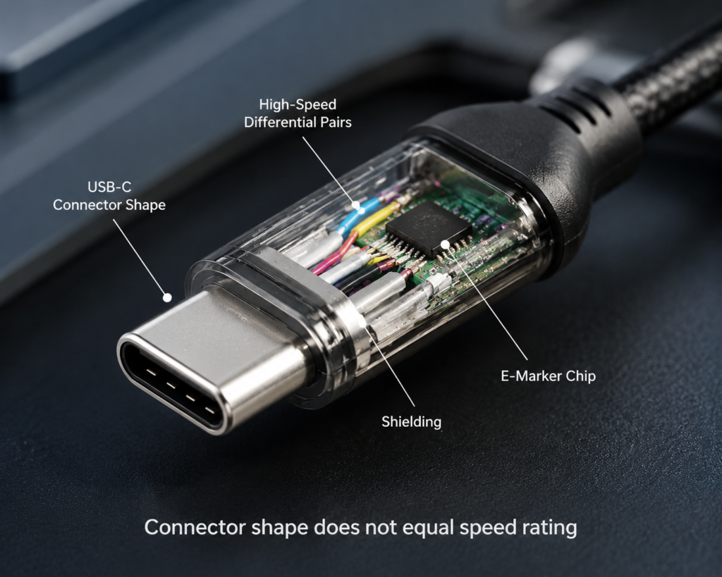
- Special check: A built-in E-Marker chip carries speed and power capability data (covered in our USB E-Marker testing guide) and must function correctly for high-speed modes to activate.
Many passive USB4 40Gbps copper cables are limited to around 0.8–1 meter for guaranteed compliance, although some manufacturers achieve longer lengths with advanced designs. Longer runs almost always require active electronics or fiber optics.
5.2 HDMI & DisplayPort Video Cables: The Barrier for 8K & High Refresh
- HDMI 2.1 (FRL mode): Uses Fixed Rate Link signaling with 3 or 4 high-speed lanes. Configurations range from FRL3 (3 lanes × 9Gbps) up to FRL6 (4 lanes × 12Gbps), for a maximum total bandwidth of 48 Gbps. Test coverage extends into the ~12 GHz range. HDMI 2.1 does not always run at the full 48Gbps maximum; actual bandwidth depends on the FRL lane configuration negotiated between source and display.
- Poor cable performance causes 8K blackouts, VRR glitches, and screen flicker.
- DisplayPort: High-bandwidth modes demand extremely consistent differential impedance and strong crosstalk rejection.
5.3 Ethernet Cables: From Cat5e to Cat8
The core difference between categories is the maximum test frequency — and thus the maximum supported speed.
| Category | Bandwidth | Typical Use Case |
|---|---|---|
| Cat5e | 100 MHz | Gigabit Ethernet at 100m |
| Cat6 | 250 MHz | Gigabit / short-reach 10G |
| Cat6A | 500 MHz | 10GBASE-T at full 100m |
| Cat7 | 600 MHz | Shielded, high-noise industrial environments |
| Cat8 | 2000 MHz | 25G / 40G short-reach data center links |
Two common test modes:
- Permanent link: Tests the installed cabling itself
- Channel: Tests the full usable end-to-end path including patch cords
Practical Example: Why Your Cat6 Cable Might Not Reach 10Gbps
It is common for users to buy Cat6 cable and still fail to get 10Gbps speeds. The usual culprits are:
- Total cable length exceeds ~55 meters (the 10GBASE-T limit for standard Cat6)
- Low-quality connectors or poorly terminated keystones
- Excessive crosstalk from sloppy punch-downs or overly untwisted pairs
- The cable route runs parallel to power cables or near heavy electrical interference
5.4 Industrial & Automotive Cables: Built for Harsh Environments
- Priorities: Stable performance across wide temperature ranges, vibration resistance, strong EMI immunity.
- Common uses: Industrial Ethernet, automotive LVDS, SerDes high-speed harnesses.
5.5 Thunderbolt Cables: The Active Cable Advantage
- Focus: Multi-lane differential signal consistency and matching.
- Passive copper cables: Simple, low cost, but limited to very short distances at top speed.
- Active cables: Include retimer / redriver chips along the path that clean up and reshape the degraded signal.
- How it works: Transmitter → copper cable → retimer rebuilds clean signal + timing → receiver
- Benefit: Dramatically extends the maximum cable length at full speed.
- Certification: Full Intel Thunderbolt certification requires comprehensive SI testing.
6. Signal Integrity Standards & Certification Systems
6.1 USB Cable Certification (USB-IF)
- Governing body: USB Implementers Forum (USB-IF)
- What’s tested: Compliance testing includes full electrical testing and signal integrity testing — insertion loss, return loss, jitter, eye diagram, and BER across the full frequency range.
- Value: USB-IF certified cables have passed the complete official test suite and are the safest choice for guaranteed high-speed performance.
6.2 HDMI Cable Certification (HDMI Forum)
- Governing body: HDMI Forum, tested at Authorized Testing Centers (ATCs).
- Key certification: Ultra High Speed HDMI Cable certification mandates FRL-mode high-frequency SI, delay skew, and EMI performance.
- Value: Only certified cables can reliably deliver 8K@60Hz, 4K@120Hz, VRR, and other HDMI 2.1 features.
6.3 Ethernet Cabling Standards
- North America: ANSI/TIA-568 series defines SI limits and test methods for Cat5e through Cat8.
- International: ISO/IEC 11801 is the global generic cabling standard.
- Role: The foundation for commercial cabling acceptance testing and category ratings.
7. 6 Key Factors That Shape Cable Signal Quality
7.1 Cable Construction: Materials & Manufacturing
- Conductor: High-purity copper has the lowest loss; copper-clad aluminum (CCA) performs much worse at high frequencies. Thicker wire (lower AWG number) = lower loss.
- Insulation / dielectric: Stable dielectric constant and uniform foam structure give the best high-frequency behavior.
- Shielding: Foil, braid, and dual-layer designs each step up interference rejection (see our full guide to cable shielding testing for a deep dive).
- Twist geometry: Precise, consistent twist rates with proper pitch differences between pairs are essential for low crosstalk.
Outer jacket materials — such as PVC, TPE, TPU, nylon braid, and silicone — primarily affect durability, flexibility, and environmental resistance. The internal conductor geometry and dielectric design have a far larger impact on high-frequency signal integrity.
7.2 Connectors: The Most Common Failure Point
- The connector’s internal impedance profile must be carefully designed to match the cable.
- Crimp / solder quality and consistency strongly affect reflections.
- How far you untwist the pairs at termination is a huge lever for crosstalk performance.
7.3 Installation & Routing: How Bad Setup Ruins Good Cables
- Tight bends: Bending below the minimum bend radius crushes internal structure and causes impedance spikes and higher loss.
- Excessive pulling force: Stretching the cable thins conductors and damages shielding.
- Over-tight bundling: Squeezing cables deforms their internal geometry and worsens crosstalk.
- Running next to power lines: Close proximity to AC power injects electromagnetic interference.
7.4 Environment & Aging: The Slow, Invisible Degradation
- Temperature: Heat raises conductor resistance and shifts dielectric properties, increasing loss and drifting impedance.
- Aging over time: Copper oxidizes, plastic degrades, shielding cracks — performance slowly degrades year after year.
- Harsh conditions: Moisture, corrosion, and vibration all speed up failure.
7.5 Active Cable Electronics: Retimers, Redrivers & Optical Modules
- Common signal-boosting chips: Retimers (full clock + data recovery), redrivers (signal amplification and equalization), and optical modules for fiber cables.
- What they do: Compensate for attenuation and jitter, allowing much longer high-speed runs.
- Caveat: The chip’s own quality and compatibility directly determine the final signal integrity of the whole cable.
8. Common Issues & Troubleshooting Steps
8.1 Problem: Cable charges and enumerates, but runs slow
- Likely causes: Excessive high-frequency insertion loss, or the cable is simply not rated for the speed.
- How to troubleshoot:
- Verify the cable’s advertised speed rating.
- Check if the cable is longer than the spec allows.
- Rule out low-quality conductors (e.g. CCA).
8.2 Problem: HDMI / DP goes black or flickers at high resolution
- Likely causes: Too much high-frequency loss, excessive delay skew, or failing eye diagram.
- How to troubleshoot:
- Try a shorter cable; if it works, length / loss is the issue.
- Swap in a certified cable to confirm.
- Rule out source / display compatibility problems.
8.3 Problem: Ethernet negotiates slow or drops packets
- Likely causes: Poor crosstalk, bad return loss, or sloppy termination.
- How to troubleshoot:
- Re-terminate both ends first — bad punch-downs are the #1 cause.
- Check the cable route for nearby power cables or noise sources.
- Test the cable itself with a cable certifier.
8.4 Problem: Tests look good, but real-world use is unstable
- Likely causes: External EMI, bad grounding, or host / device compatibility issues.
- How to troubleshoot:
- Move the cable away from motors, power supplies, or radio gear.
- Verify shield grounding is correct.
- Test with different host / device combinations.
8.5 Problem: USB-C dock high-speed features are flaky
- Likely causes: Cable SI is too weak, the dock shares bandwidth across ports, or multiple high-speed devices are competing for capacity.
- How to troubleshoot:
- Use a short, high-rated direct cable between host and dock.
- Disconnect other high-speed peripherals to see if the issue improves.
- Confirm the dock’s actual advertised bandwidth.
9. Buyer’s Guide: Pick Cables With Great Signal Integrity
9.1 Trust Official Certifications First
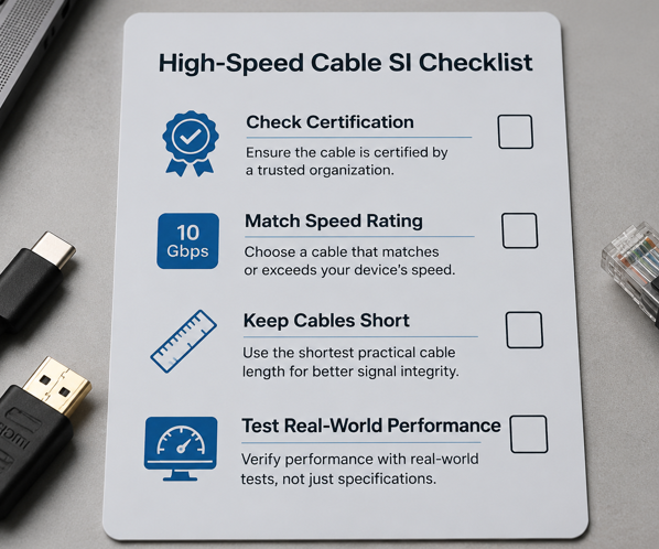
- USB cables: Look for USB-IF certified products — they have passed full signal integrity testing.
- Video cables: Prefer HDMI Official Certified or DisplayPort-certified cables.
- Thunderbolt: Look for the Thunderbolt certified logo for guaranteed full-speed operation.
9.2 Read the Specs: Don’t Fall for “USB-C” or “Gold Plating” Hype
- Myth 1: “USB-C means it’s fast.”
- Reality: USB-C is just the connector shape. Always check the protocol version and data speed rating.
- Myth 2: “Gold-plated connectors = better signal.”
- Reality: Gold plating improves durability and corrosion resistance — it does not magically improve high-speed signal integrity.
- Key specs to check: speed rating, protocol version, wire gauge (AWG), and shielding type.
9.3 Length vs. Speed: How Long Is Too Long for Full Performance?
General rule: the higher the speed, the shorter the maximum reliable passive copper cable.
- USB 3.2 10Gbps: ~2 meters passive copper is a safe limit.
- USB4 40Gbps: Most passive copper cables top out at 0.8–1 meter for guaranteed compliance; longer requires active electronics or fiber.
- HDMI 2.1 8K: Passive copper works best at ~2 meters or less.
9.4 Easy DIY Tests You Can Do Without Lab Equipment
- Speed test: Connect an external SSD and run a benchmark like CrystalDiskMark; compare the result to the advertised speed.
- Video stress test: Run the maximum resolution and refresh rate your display supports, and watch for dropouts over 30+ minutes.
- Sustained transfer test: Copy a very large file continuously and watch for slowdowns or disconnects.
9.5 Common Buying Myths Debunked
- ❌ “More expensive always means better SI.”
- ✅ Design, materials, and certification matter most. Premium aesthetics do not guarantee better electrical performance.
- ❌ “Shielded cable is always better than unshielded.”
- ✅ In noisy environments, yes. But a poorly grounded shield can worsen problems via common-mode noise. For short home use, good-quality unshielded cable works fine.
9.6 How to Choose Cables for Different Use Cases
- Phone charging: Focus on PD power rating and E-Marker support; basic data is usually enough.
- External SSD: Match the USB version and speed rating (10 / 20 / 40 Gbps) to your drive’s capability.
- Monitor / display: Match the HDMI / DP version to the resolution and refresh rate you need; certified cables are worth it.
10. Frequently Asked Questions (FAQ)
Q1: Why does my cable charge fine but fail to run at full data speed?
Charging only requires low DC resistance on the power wires. High-speed data demands every signal integrity parameter to be within spec. They are completely different measurements.
Q2: Are Ethernet “category ratings” (Cat6, Cat7, etc.) basically signal integrity ratings?
Yes. The core difference from Cat5e to Cat8 is progressively tighter limits on frequency, attenuation, crosstalk, and return loss — all classic signal integrity metrics.
Q3: Does signal integrity get worse as a cable ages?
Yes. Oxidation on conductors, plastic degradation in the dielectric, connector wear, and shield damage all slowly erode performance over years of use.
Q4: What’s the difference between signal integrity testing and EMC testing?
Signal integrity asks “is the signal itself clean and correct?” EMC (electromagnetic compatibility) asks “does this device interfere with others, or get interfered with?” They overlap through metrics like common-mode conversion but have different goals.
Q5: Do regular consumers need to buy lab test equipment?
No. Official certifications, clear spec labels, and simple real-world performance checks are enough for almost all buying and troubleshooting decisions.
Q6: Why do USB-C cables have such huge price differences?
Most of the gap comes from signal integrity engineering. True high-speed cables need precision impedance control, high-quality shielding, tight manufacturing tolerances, and sometimes active electronics — all of which cost far more than a basic charge-only cable.
Q7: Why do longer cables struggle more with high-speed transmission?
More length means more total attenuation, more accumulated delay skew, and more opportunity for noise and crosstalk to build up. Past a certain point, the receiver can no longer reliably read the signal.
Q8: Is a shielded cable always better for signal integrity than an unshielded one?
It usually is in high-interference environments. But if the shield is poorly grounded, it can actually introduce more common-mode noise. For short runs in typical homes, a well-made unshielded cable is perfectly fine.
Q9: Why can’t a regular USB-C cable run USB4 speeds?
USB4 imposes extremely tight requirements on high-frequency impedance control, insertion loss, crosstalk rejection, and delay skew. Ordinary USB-C cables are usually designed only for charging or USB 2.0 data and fall far short of those targets.
Q10: What’s the difference between passive and active cables?
Passive cables use only copper conductors — simple, cheap, but distance-limited at top speed. Active cables include built-in signal-conditioning chips that reshape and retime degraded signals, enabling much longer full-speed runs at a higher cost.
Q11: Does a thicker USB-C cable always have better signal integrity?
No. Thicker cables usually have larger conductors or extra layers of jacket and braid, which mainly improve current capacity and durability. High-speed performance depends far more on precise impedance control, shielding design, connector engineering, and low high-frequency loss — not just overall thickness.
Q12: Can a cheap USB-C cable tester check signal integrity?
No. Most affordable USB testers only measure voltage, current, continuity, and basic protocol information like E-Marker data. They cannot measure insertion loss, return loss, eye diagrams, or bit error rate — the true markers of signal integrity.
Q13: Can a USB-C cable pass continuity testing but fail USB4 certification?
Absolutely. Continuity tests only verify that wires are connected end-to-end. USB4 certification requires dozens of high-frequency signal integrity measurements — impedance control, insertion loss, crosstalk, jitter, eye diagram, BER, and more — that basic continuity checks never touch. A cable can pass every basic electrical test and still be completely unusable for 40Gbps or 80Gbps transmission.
11. Future Trends in Signal Integrity Testing
- Ever-higher speeds: 112Gbps PAM4 and 224Gbps SerDes are pushing test frequencies toward 40 GHz and beyond, raising the bar for cable construction and measurement precision.
- AI-assisted analysis: Machine learning is being applied to waveform recognition and automatic root-cause diagnosis, making test analysis faster and more accessible.
- Real-time monitoring: Data centers and automotive systems are adding live link health monitoring, often paired with digital twins, to predict degradation before it causes failures.
- Automation everywhere: End-to-end automated test flows are becoming standard from R&D to production lines, with cloud-based data storage and full quality traceability.