
Introduction: The Hidden Technology Behind Stable Electronics
Opening Hook
Why does your 100W USB-C charger sometimes deliver less than its advertised wattage on a hot summer day? Why does your phone’s fast charging speed drop sharply once it hits 70–80% battery? Why does your gaming laptop lose frame rates and feel sluggish when its fans kick into high gear? Why does outdoor power equipment run at reduced capacity in midday heat?
Many users jump to the same conclusions: it’s a product defect, fake advertised specs, or a sign of poor build quality.
But the truth is far more intentional—and far more reassuring. What you’re experiencing is power derating: a carefully engineered protection mechanism built into every modern high-power electronic device. It is not a flaw. It is the reason your devices last for years instead of months, and run safely instead of overheating.
This guide breaks down power derating in clear, practical terms: how it works, why it exists, how it shows up in the gadgets you use every day, and how you can work with it to get the best performance and longest life from your electronics.
Quick Summary: Power Derating Explained in 30 Seconds
What is Power Derating?
Power derating is the controlled, automatic reduction of output power, current, voltage, or operating frequency when a device approaches unsafe thermal or electrical limits. It activates in response to high ambient temperatures, insufficient cooling, heavy sustained loads, or elevated component stress.
Why does it exist?
Running electronics at 100% of their rated maximum around the clock would generate excessive heat, accelerate wear, reduce long-term reliability, and create potential safety hazards. Power derating trades a small amount of peak performance for dramatically better safety, longer service life, and consistent long-term operation.
1. What Is Power Derating?
1.1 Simple Explanation for Everyday Users
Think of power derating like the engine protection system in a car. If you climb a long, steep hill on a hot day, the engine will automatically reduce output to prevent overheating and permanent damage. You lose a little speed, but you avoid a catastrophic breakdown.
Power derating works the same way for electronics. When conditions push a device toward its thermal or electrical limits, the internal control system gently dials back performance to keep everything within a safe operating range.
You see it every day, often without realizing it:
| Device | Common Derating Example |
|---|---|
| USB-C PD charger | 100W adapter drops output in warm room temperatures |
| Smartphone | Fast charging slows down noticeably as battery approaches 80% |
| Gaming laptop | CPU and GPU run at lower clock speeds under sustained heavy load |
| Industrial power supply | Full rated output only available up to a specified ambient temperature |
1.2 Engineering Definition
From a reliability engineering perspective, power derating is the practice of operating electronic components and systems at stress levels below their published maximum ratings to create an intentional safety margin.
By reducing electrical stress (voltage, current) and thermal stress (junction temperature, case temperature), designers lower the rate of material degradation, reduce failure probability, and extend the device’s useful service life.
It is a core principle of robust product design—not a workaround for cheap components.
1.3 Rated Power vs. Real Operating Power
Rated Power
The big number printed on the label—65W, 100W, 240W—is the device’s rated power. This is the maximum output measured under carefully controlled laboratory conditions:
- Standard ambient temperature (typically 25°C)
- Optimized airflow and cooling
- Nominal input voltage
- Defined test duration
It describes the device’s peak capability, not its permanent guaranteed output.
Real Operating Power
In real homes, offices, cars, and outdoor spaces, conditions are almost never ideal. Actual usable output depends on:
- Surrounding air temperature
- Enclosure and cooling design
- Load duration and intensity
- Cable and connector quality
- Internal component temperatures
The takeaway is simple:
The wattage on the box is a capability rating, not a 24/7 performance guarantee.
2. Why Electronics Need Power Derating
2.1 Higher Power Always Creates More Heat
No power conversion is 100% efficient. Every time electricity is converted from one voltage to another, switched on and off, or pushed through a wire, some energy is lost as heat.
These losses come from multiple sources:
- Semiconductor losses: Switching and conduction losses in MOSFETs, GaN transistors, diodes, and power ICs
- Passive component losses: Resistive heating in wires, windings, and connectors; magnetic losses in inductors and transformers
- System losses: Control circuits, sensing circuits, and auxiliary power consumption
One equation explains why high-current fast charging is so thermally challenging:
(P = I^2R)
Power lost as heat equals current squared multiplied by resistance. In plain language: double the current, and heat generation from resistance roughly quadruples.
This is why moving from 3A to 5A charging creates a far bigger thermal jump than the numbers alone suggest.
3. Temperature: The Main Driver Behind Power Derating
3.1 Why Heat Damages Electronics
Heat is the single biggest enemy of electronic reliability. Higher temperatures accelerate nearly every physical and chemical degradation process inside components:
- Semiconductor materials degrade faster and develop more leakage current
- Electrolytic capacitors lose electrolyte more quickly and drift in value
- Solder joints fatigue and crack sooner under thermal cycling
- Plastics and insulation materials weaken and break down over time
The widely studied Arrhenius relationship describes this effect: chemical reaction rates—and therefore aging rates—increase exponentially with temperature. While the exact magnitude varies by component type and material, the core rule holds across nearly all electronics:
Higher sustained operating temperatures generally mean shorter component lifetime.
3.2 Three Important Temperature Values
To understand derating, you only need to know three temperature measurements. They measure different things and are not interchangeable.
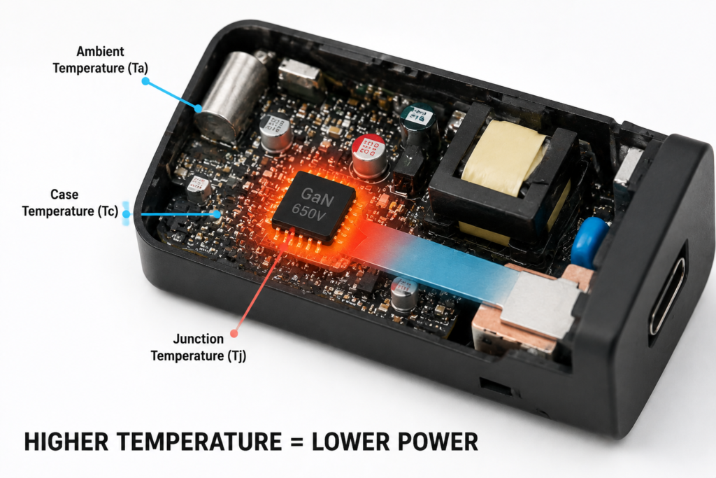
Ambient Temperature (Ta)
The temperature of the air surrounding the device or component. This is the easiest number to measure and the one most users intuitively understand.
Case Temperature (Tc)
The temperature measured on the outer surface of a component’s package. It is affected by heatsinks, thermal pads, enclosure design, and nearby heat sources.
Junction Temperature (Tj)
The actual temperature inside the silicon chip itself. For MOSFETs, GaN transistors, power ICs, and other semiconductors, this is the most critical limit. Exceeding the maximum junction temperature causes rapid degradation or immediate failure.
4. The Physics Behind Derating Curves
4.1 Junction Temperature Calculation
The relationship between ambient temperature and chip temperature follows a simple, well-established formula:
(Tj = Ta + P times theta{JA})
Where:
- (Tj) = junction temperature
- (Ta) = ambient temperature
- P = power dissipated as heat
- (theta{JA}) = thermal resistance from junction to ambient air
In practical terms: more power dissipation, worse cooling, or hotter surrounding air all push the chip temperature higher. Once the junction temperature approaches its rated maximum, the device must reduce power to stay safe.
4.2 Understanding a Derating Curve
Component manufacturers publish derating curves that show exactly how much power a part can safely handle at any temperature. A typical curve has three distinct operating zones
Zone 1: Full Power Region
At temperatures below the rated reference point, the component can run at 100% of its rated power continuously. This is the normal operating range.
Zone 2: Derating Region
Above the reference temperature (often called the knee temperature), the maximum allowable power decreases steadily as temperature rises. The device can still run safely, but only at reduced output.
Zone 3: Protection Region
At the maximum rated temperature, allowable power drops to near zero. Any further operation risks permanent damage, so the device shuts down or enters a low-power protection state.
5. Key Power Derating Terms
5.1 Derating Factor / Stress Ratio
The derating factor (also called stress ratio) describes how hard a component is being driven relative to its maximum rating for a specific stress parameter:
(text{Stress Ratio} = frac{text{Actual Operating Stress}}{text{Rated Maximum Stress}})
For example, a power transistor operating at 60% of its voltage rating has a voltage stress ratio of 60%. Derating can apply to voltage, current, power, or temperature separately.
At the system level, power derating is often described as a percentage of rated output power available under given conditions.
5.2 Derating Curve
A graph found in component datasheets that plots temperature on the horizontal axis and maximum allowable power or current on the vertical axis. It is the authoritative reference for determining safe operating limits under real-world conditions.
5.3 Knee Temperature
The temperature point where full-power operation ends and derating begins. Below this temperature, no power reduction is required; above it, output must be reduced.
5.4 Maximum Operating Temperature
The temperature at which continuous operation is no longer safe. At this point, the device will typically shut down, reduce power to a minimum, or enter a thermal protection cycle.
6. How Devices Perform Power Derating
6.1 Thermal Derating
Thermal derating is the most common and widely recognized form. Temperature sensors placed at critical points inside the device feed data to a controller chip (PMIC, PD controller, or MCU). As temperatures rise, the controller gradually reduces output power to keep heat generation under control. If temperatures continue climbing, it eventually triggers a full thermal shutdown.
You see this in nearly every heat-generating device: chargers, laptops, power supplies, and smartphones.
6.2 Current Derating
Because heat from resistance scales with the square of current, reducing current is the most efficient way to quickly reduce heat generation.
Current derating is heavily used in:
- USB-C cables and connectors
- Battery charging systems
- High-current power distribution circuits
6.3 Voltage Derating
In high-voltage systems, reducing operating voltage lowers electrical stress on insulation, semiconductor junctions, and capacitor dielectrics. This reduces the risk of arc-over, breakdown, and accelerated aging.
It is most common in:
- Industrial high-voltage power supplies
- USB PD EPR high-voltage charging systems
- Utility and renewable energy equipment
6.4 Smart Dynamic Power Management
Modern devices do not use simple fixed temperature thresholds. They combine real-time data from multiple sensors—temperature, input voltage, battery state of charge, load demand—and use control algorithms to continuously tune power output.
This creates a smoother, less noticeable user experience: instead of abruptly dropping from full power to a much lower level, the device gently ramps power up and down as conditions change.
7. Factors Affecting Power Derating
7.1 Ambient Temperature
The single largest factor. Higher surrounding air temperature leaves less headroom before components hit their temperature limits. Summer weather, hot car interiors, direct sunlight, and enclosed cabinets all trigger earlier and more aggressive derating.
7.2 Cooling Design
How well a device sheds heat directly determines how long it can hold full power. Important design elements include:
- Metal housings and heat-spreading chassis
- Dedicated heatsinks and thermal interface materials
- Fans and forced-air cooling
- Open ventilation paths
Better cooling = later derating = more sustained full-power operation.
7.3 Altitude
At higher elevations, thinner air is less effective at carrying away heat. For this reason, most power supply specifications require additional derating above 1000–2000 meters above sea level.
7.4 PCB Layout and Component Placement
When heat-generating parts are clustered closely together, they warm each other up. This “group heating” effect raises local temperatures and causes derating to kick in earlier than it would for a single part in open air.
7.5 Electrical Operating Conditions
Switching frequency, input voltage range, and load profile all affect internal losses and heat generation. Higher frequencies and extreme input voltages typically increase losses and push temperatures higher.
8. Component-Level Derating Rules
Derating is not a one-size-fits-all rule. Different component types have different failure modes and therefore different derating best practices. These reflect widely accepted industry guidelines, not universal fixed numbers.
8.1 Resistors
Resistors are derated for both power and voltage. Steady-state power is the primary concern for continuous operation, while pulse energy handling becomes critical for short surge events. Surface-mount resistors are particularly sensitive to PCB layout and copper pad size.
8.2 Capacitors
Capacitors require derating across three dimensions:
- DC voltage: Operating below the voltage rating extends life and prevents catastrophic failure
- Ripple current: Excess AC current causes internal heating and premature aging
- Temperature: High ambient temperatures accelerate wear, especially for electrolytic types
8.3 Power Semiconductors
MOSFETs, GaN transistors, IGBTs, and diodes are primarily limited by maximum junction temperature and safe operating area (SOA). Good design practice keeps steady-state junction temperatures well below the absolute maximum rating to provide reliability margin.
8.4 Magnetic Components
Transformers and inductors are limited by winding temperature rise and magnetic saturation. Excessive current can cause saturation, which spikes current draw and leads to rapid overheating.
8.5 Power Derating vs Power Limiting
These two terms are often confused, but they describe different concepts:
| Feature | Power Derating | Power Limiting |
|---|---|---|
| Primary trigger | High temperature or component stress | Fixed design and specification limits |
| Core purpose | Improve long-term reliability and safety | Cap output at designed maximum level |
| Behavior | Changes dynamically with conditions | Remains fixed regardless of temperature |
| Common example | Charger reduces from 100W to 80W when hot | Laptop adapter is permanently rated at 65W maximum |
9. USB-C Fast Charger Power Derating Explained
9.1 Why High-Wattage Chargers Need Derating
USB-C charging power has grown rapidly: from 18W just a few years ago to 65W, 100W, 140W, and now 240W with USB PD 3.1 EPR. At the same time, consumer demand has pushed charger bodies smaller and smaller.
The result is dramatically higher power density: more watts packed into less space. Even with highly efficient designs, there is simply no way for a compact charger to dissipate 100W+ of heat indefinitely in warm ambient air. Thermal derating is not a design flaw—it is an unavoidable engineering reality.
9.2 Example: 100W USB PD Charger
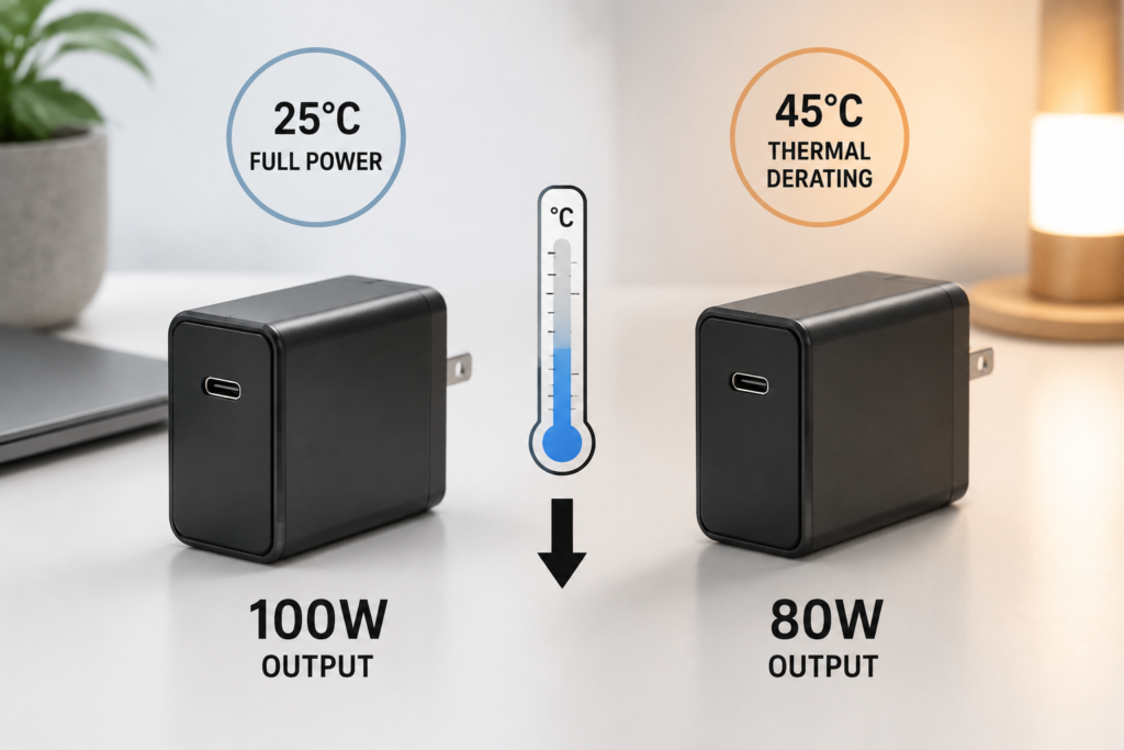
Under controlled laboratory conditions, many 100W USB-C chargers can reach their rated output at room temperature. However, sustained full-power operation depends on internal thermal design, airflow, and component temperature limits.
In practice:
- At mild room temperature with open airflow: Many chargers can maintain 100W output
- At higher ambient temperature: The internal controller adjusts output to maintain safe component temperatures. Depending on the design strategy, it may reduce current, reduce voltage, or both
- Under extreme heat or enclosed conditions: Output may be reduced further to protect the charger and connected device
9.3 GaN Charger Thermal Challenge
Gallium nitride (GaN) transistors switch faster and run more efficiently than traditional silicon MOSFETs. They waste less energy as heat per watt of output, which is why GaN chargers can be so much smaller.
But smaller size also means less surface area, less thermal mass, and less ability to shed heat into the surrounding air. So while GaN improves efficiency watt-for-watt, the ultra-compact form factors it enables still require careful thermal management and active derating for sustained full-load operation.
9.4 USB PD Charger Thermal Derating Mechanism
Nearly all modern USB PD chargers follow a similar internal control flow:
Temperature Sensors (on PCB, GaN, transformer)
                ↓
PD Controller / MCU
                ↓
Thermal control firmware algorithm
                ↓
Reduce output current (primary method)
                ↓
Lower output power
                ↓
Maintain safe junction and component temperatures
This closed-loop system runs continuously during charging, making tiny adjustments many times per second to balance speed and temperature.
10. How to Calculate Power Derating
You do not need an engineering degree to estimate real-world output. For most consumer and light industrial applications, this simple four-step process works well:
- Find the rated power and its reference temperature from the product specification or datasheet.
- Identify your actual maximum ambient temperature—the hottest air temperature the device will see in normal use.
- Locate the derating curve and read off the allowable power percentage at that temperature.
- Multiply the rated power by the derating percentage to get your real-world safe output.
Simple Worked Example
Take a 65W USB-C charger rated for full power at 25°C:
- At 25°C: 100% output = 65W
- At 60°C ambient: the derating curve typically shows ~80% allowable output
- Safe sustained output = 65W × 0.8 = 52W
This is the simple math behind why your “65W” charger feels slower on a hot day.
11. Industry Standards Related to Derating
Power derating practices are not arbitrary. They are grounded in decades of reliability research and formalized in global standards:
- IEC 62368-1 / UL 62368-1: The primary safety standards for IT and audio/video equipment, which require products to operate within safe thermal and electrical limits under normal and fault conditions.
- MIL-HDBK-217F / NASA EEE-INST-002: Strict derating and reliability guidelines for military and aerospace systems, where failure is unacceptable.
- AEC-Q series: Component qualification and derating requirements for automotive electronics, which must survive extreme under-hood temperatures.
- IPC-9592: Performance and reliability standards for power converters, including thermal derating requirements.
Consumer products generally follow IEC/UL safety requirements, while industrial, automotive, and aerospace products apply progressively more conservative derating.
12. Real-World Applications
Smartphones
Fast charging slows down as the battery fills up for two reasons: battery chemistry becomes less receptive to high current near full charge, and rising battery temperature triggers thermal derating. This is intentional battery protection that greatly extends cycle life.
Laptops
When a laptop’s CPU and GPU run hot, they reduce clock speeds to stay within temperature limits. This is commonly called thermal throttling, and it is essentially power derating applied to computing hardware. The goal is identical: reduce power draw to control heat and protect the hardware.
Industrial Power Supplies
Equipment installed inside factory cabinets often operates at 40–55°C ambient. At these temperatures, power supplies must be derated significantly below their nameplate rating to ensure reliable long-term operation.
Solar Inverters
Grid-tie inverters sit on rooftops in direct sun. Midday heat combined with full solar input causes output derating, which is a normal and expected part of their operation.
13. Power Derating vs. Other Protection Technologies
It is easy to confuse power derating with other safety features. They work together, but they serve different purposes.
| Technology | How It Works | Goal |
|---|---|---|
| Power Derating | Gradual, continuous reduction of output power/performance | Keep device within safe limits while staying operational |
| Thermal Shutdown (OTP) | Full emergency stop at temperature limit | Prevent immediate catastrophic damage |
| Over-Current Protection (OCP) | Hard cutoff at current limit | Protect against short circuits and overloads |
| Over-Voltage Protection (OVP) | Hard cutoff at voltage limit | Protect against voltage spikes and regulator failures |
| CPU/GPU Thermal Throttling | Reduces processor clock speed under heat | Maintain operation while controlling chip temperature |
13.1 Power Derating vs Thermal Throttling: What’s the Difference?
This is one of the most commonly searched questions, and the answer is simple:
- Power derating is the general term for reducing power to stay within safe thermal/electrical limits. It applies to chargers, power supplies, cables, batteries, and entire systems.
- Thermal throttling is the specific name for power derating applied to processors (CPUs, GPUs, SoCs) by reducing their clock frequency.
In short: all thermal throttling is a form of power derating, but not all power derating is thermal throttling.
13.2 How Manufacturers Design to Minimize Unnecessary Derating
Engineers use several techniques to push derating thresholds higher and maintain full power longer:
- Increase PCB copper area to spread and dissipate heat
- Optimize the thermal path from hot components to the outside case
- Use transistors with lower on-resistance (Rds(on)) to reduce conduction losses
- Tune switching frequencies to balance efficiency and thermal performance
- Place additional temperature sensors at critical hot spots
- Improve enclosure design for better natural convection cooling
14. Common Misunderstandings
Myth 1: “If it says 100W, it should always deliver 100W.”
Reality: Rated power is measured under specific laboratory conditions. Real-world temperatures, enclosures, and airflow change the actual safe output. This is true for every reputable brand and every category of power equipment.
Myth 2: “Derating means the product is low quality.”
Reality: The opposite is usually true. Well-engineered products actively manage stress and temperature. A device that never derates at all is likely running components right at their absolute limits, which shortens life and raises safety risks.
Myth 3: “More derating is always safer and better.”
Reality: Excessive derating means oversized, overpriced, unnecessarily bulky components with no meaningful reliability gain. For most consumer and commercial products, moderate derating strikes the best balance of cost, size, performance, and longevity.
15. How Users Can Reduce Unnecessary Derating
You cannot eliminate derating entirely—and you would not want to, because it protects your devices. But you can reduce unnecessary early derating and get more sustained performance with a few simple habits:
- Give chargers open airflow. Don’t tuck them under pillows, blankets, carpets, or stacks of papers. Leave space around them for air circulation.
- Keep devices out of extreme heat. Avoid leaving chargers, phones, and laptops in direct sun or inside hot cars.
- Use properly rated cables. For 100W+ charging, use certified 5A E-Marker USB-C cables. Undersized cables cause extra heat and trigger earlier power reduction.
- Avoid heavy load + fast charging at the same time. Gaming or rendering video while charging your laptop or phone generates extra heat and slows charging speed.
- Don’t block ventilation. Keep laptop intake and exhaust vents clear, especially on soft surfaces like beds and couches.
16. Future Trends
As electronics continue to get smaller and more powerful, derating technology will keep evolving:
- Advanced predictive thermal management using intelligent algorithms: Control systems will anticipate temperature changes based on load history, adjusting power smoothly before temperatures spike.
- Wide-bandgap semiconductors (GaN, SiC): Higher temperature tolerance and lower losses will push derating thresholds higher and enable higher power densities.
- 240W+ USB PD ecosystems: Ultra-high-power charging will require coordinated thermal management across chargers, cables, connectors, and devices.
- Advanced cooling technologies: Vapor chambers, graphene heat spreaders, and improved thermal interface materials will delay derating and extend full-power operation.
FAQ
What causes power derating?
The primary cause is rising component temperature. When internal temperatures approach safe limits, the device’s control system reduces output power to bring heat back down. Secondary triggers include high altitude, poor cooling, and sustained heavy loads.
Does power derating mean my charger is defective?
No. Power derating is an intentional safety and reliability feature present in all well-designed high-power electronics. It is not a defect, and it does not indicate poor build quality.
Can GaN chargers avoid power derating?
No. GaN technology reduces waste heat and improves efficiency, but it does not eliminate thermal limits. The ultra-compact size of most GaN chargers actually makes thermal management more challenging, so all properly certified GaN chargers include thermal derating.
How can I stop my charger from reducing power?
You cannot fully disable derating, and doing so would be unsafe. You can reduce unnecessary early derating by keeping the charger in cool, open air, using a properly rated cable, and avoiding enclosed or sun-heated spaces.
Is thermal throttling the same as power derating?
Thermal throttling is a specific type of power derating that applies to CPUs and GPUs. Power derating is the broader term for any controlled power reduction for thermal or electrical safety reasons.
Why does my phone charge slower after 80%?
Two factors work together. First, lithium-ion batteries naturally accept less charging current as they approach full capacity. Second, the battery and charging circuit warm up during charging, triggering thermal derating. Both effects protect long-term battery health.
What is a derating curve?
A derating curve is a graph that shows how much power or current a component can safely handle at different ambient temperatures. It is the standard reference used by engineers to design reliable electronic products.
Final Conclusion
Power derating is one of the most important invisible technologies in modern electronics. It is not a weakness, not a trick, and not a sign of cheap design. It is the quiet engineering compromise that allows us to carry 100W chargers in our pockets, run powerful laptops on our laps, and use our devices reliably for years instead of months.
From USB-C chargers to smartphones, from gaming laptops to industrial power systems, power derating balances four competing goals: performance, safety, size, and lifespan. It is the reason your devices don’t burn out.
The next time your charger slows down on a hot day, or your laptop drops a few frames under heavy load, remember: it is not failing. It is protecting itself—and that means it will serve you far longer in the long run.
Reference standards and sources: IEC 62368-1, UL 62368-1, MIL-HDBK-217F, NASA EEE-INST-002, AEC-Q series, IPC-9592, and component datasheets from leading semiconductor and passive component manufacturers.