
1. What Is a Smart Power Distribution MCU?
1.1 Simple Analogy: The “Traffic Cop” of Your Power System
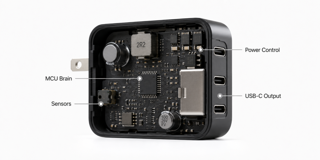
1.2 Clear Definition: A System Solution, Not a Single Chip Category
- Core nature: A microcontroller-based intelligent power management solution combining sensing, algorithms, and control hardware
- Common industry terms: Digital Power MCU, Power Management MCU, Smart Power Controller, Power Distribution Controller, Multi-Port Charger Controller
1.3 The Evolution of Smart Power Management
- Stage 1: Analog Power Control Era
- Stage 2: Digital MCU Control Era
- Stage 3: Protocol-Driven Smart Power Era (USB PD, PPS standardization)
- Stage 4: Predictive Intelligent Energy Management (AI/ML adoption in industrial and grid-scale systems)
1.4 Key Differences: MCU vs PMIC vs USB PD Controller
- General-purpose MCU: Follows custom instructions, no built-in power logic; flexible but requires full development
- PMIC (Power Management IC): Dedicated power management chips focused on voltage regulation, power conversion, and protection functions
- USB PD Controller: Handles USB PD communication, power negotiation, and port-role management
- Smart Power Distribution MCU: System-level decision-making, the central “brain” that coordinates all other power chips
1.5 Its Position in the Full Power System Chain
- General power distribution system architecture
- Dedicated USB-C fast charging system architecture
2. Why Smart Power Distribution Is Essential
2.1 The Multi-Device Charging Dilemma
- Single-port era vs. multi-port era: Core differences
- The fundamental conflict: Limited total power budget vs. growing device count
2.2 Why Traditional Standalone Power Chips Can’t Handle Complex Distribution
- Limitations of standalone PMICs: Optimized for single-rail regulation, limited cross-channel coordination
- Why multi-port systems require MCU coordination: Device identification, dynamic budgeting, priority management, cross-chip protocol synchronization
2.3 Dynamic Power Sharing: The Core User-Facing Feature
2.4 3 Key Advantages Over Fixed Power Supplies
- Higher energy efficiency: No wasted idle capacity
- Better user experience: Simultaneous full-speed charging for multiple devices
- Stronger safety: Real-time multi-layer protection
2.5 Real-World Scenarios Where It Makes the Biggest Difference
- Multi-port GaN fast chargers
- RV / marine off-grid power systems
- Residential solar + battery storage
- Smart home multi-circuit power management
3. Core Working Principles
3.1 The 4-Layer System Architecture
- Sensing Layer: Voltage, current, and temperature detection units
- Decision Layer: MCU core processing unit
- Execution Layer: Power switches and voltage regulation modules
- Interaction Layer: Displays, controls, and wireless communication
3.2 Step-by-Step Operating Cycle (5 Stages)
- Step 1: Load connection and identification
- Step 2: Power demand reading and parsing
- Step 3: Total power budget calculation and allocation
- Step 4: Real-time dynamic adjustment and optimization
- Step 5: Fault detection and protection trigger
3.3 Core Concepts Clarified
- Dynamic Power Sharing: User-facing feature of shared power across ports
- Dynamic Power Allocation: Engineering-level algorithm for precise power budgeting
3.4 4 Common Power Allocation Strategies
- Fixed priority allocation method
- Proportional power split method
- Demand-responsive dynamic adjustment method
- Safety-first derating protection method
3.5 Power Budget Calculation Model
- Core formula:
Available Power = Input Power × Conversion Efficiency - System Losses - Practical example: 100W charger power breakdown
- Plain-language explanation: A 100W charger does not always deliver the full advertised wattage to devices. Real usable power is reduced by internal conversion losses and heat, so the actual distributable power is slightly lower than the nameplate rating.
3.6 Built-In Safety Protection Mechanisms
- Over-Current Protection (OCP)
- Over-Voltage Protection (OVP)
- Over-Temperature Protection (OTP)
- Short-Circuit Protection (SCP)
- Under-Voltage Protection (UVP)
3.7 Key Performance Specifications to Evaluate
| Parameter | Typical Range | Why It Matters |
|---|---|---|
| ADC Resolution | 10–16 bit | Determines how accurately voltage and current can be measured |
| Control Response Time | μs to ms level | Defines how fast the system reacts to overloads or load changes |
| Supported Interfaces | I²C / SPI / UART / CAN | Dictates compatibility with sensors, PD controllers and other peripherals |
| Standby Current | μA to mA level | Critical for battery-powered and energy-harvesting systems |
| Operating Voltage | 1.8–5.5V | Must match the system’s logic power rail |
4. Smart Power Distribution in USB-C Fast Charging
4.1 How USB PD Communication Works With MCUs
- Full USB-C charging flow: CC pin detection → PD handshake → PDO/APDO reading → power budget adjustment
4.2 The Role of PPS and EPR in Dynamic Allocation
- PPS (Programmable Power Supply): Enabling fine-grained, real-time power adjustment
- USB PD 3.1 EPR: New challenges for 240W high-power multi-port systems
4.3 Real-World Example: 100W Dual-Port GaN Charger
- Single-port mode: Full 100W output to a laptop
- Dual-port mode: 65W for laptop + 35W for smartphone
- After laptop is unplugged: Smartphone automatically upgrades to 65W fast charge
4.4 Why GaN Chargers Rely Heavily on Smart MCUs
- Shared power stage design: The cost and size driver behind GaN compactness
- Thermal management: Tighter space requires intelligent temperature-aware power control
5. Real-World Product Architecture Examples
5.1 100W Dual-Port GaN Charger Internal Architecture
AC Wall Input
    ↓
PFC (Power Factor Correction)
    ↓
GaN Power Stage (LLC / Flyback)
    ↓
DC Bus
    ↓
Smart Power Distribution MCU
    ↓
USB PD Controllers + Load Switches
    ↓
Dual USB-C Output Ports
- Key role breakdown: MCU handles cross-port budgeting; PD controllers handle per-port protocol negotiation
5.2 Smart Power Bank Internal Architecture
Battery Pack
    ↓
Fuel Gauge IC
    ↓
Buck-Boost Converter
    ↓
PD Controller
    ↓
Power Distribution MCU
    ↓
USB-C / USB-A / Wireless Charging Outputs
- Key role breakdown: MCU manages battery state, output priority and power mode switching
6. Full Chip Ecosystem & Selection Guide
6.1 The Complete Chip Chain for Smart Power Distribution
| Function | Representative Chips / Platforms |
|---|---|
| Main Control MCU | STM32G0/G4, TI C2000, ESP32-C3, ATmega328P |
| USB PD Controller | Infineon CCG3/CCG6, TI TPS6598x |
| Power / Load Switch | TI TPS229xx series, AP2281 |
| Current / Power Sensor | TI INA219, INA226 |
| GaN Power Device / Platform | Navitas GaNFast, Infineon CoolGaN |
6.2 Typical Chip Combination Examples
Consumer GaN Charger Solution
Power Distribution MCU + USB PD Controller + GaN Power Stage + Load Switches
- Optimized for size, cost and charging protocol compatibility
DIY Maker System Solution
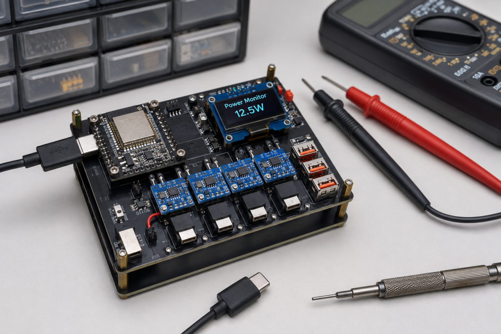
ESP32 / Arduino + INA219 Power Sensor + MOSFET Switches + DC-DC Converter
- Optimized for ease of building, modifiability and community support
6.3 MCU Selection Guide for Makers & Engineers
- Core evaluation criteria: ADC performance, I/O/PWM resources, communication peripherals, ecosystem support
- Top platforms with accurate positioning
- Arduino Nano (ATmega328P): Best for learning basic control concepts
- ESP32-C3: Best for connected smart device and IoT projects
- STM32G0/G4: Best for industrial control and professional power management
- TI C2000: Best for high-performance digital power applications
- RP2040 (Raspberry Pi Pico): Best for low-cost experimentation
- Selection by project scale
- 2–4 channel simple projects
- 8+ channel advanced systems
- IoT-enabled smart power projects
6.4 Consumer Buying Guide: How to Pick a Quality Smart Charger
- Key keywords to look for on product packaging
- How to read and interpret power split tables
- Protocol support checklist: USB PD 3.0, PPS, PD 3.1 EPR
- Safety certifications to verify: UL, CE, FCC
- Red flags for “fake smart” chargers
7. Real-World Applications & Use Cases
7.1 Consumer Electronics
- Multi-port USB-C GaN fast chargers
- Smart power banks and multi-device charging hubs
- Laptop docking station power management
7.2 Renewable Energy & Off-Grid Power
- Solar energy storage load scheduling
- RV / camper / marine smart power distribution
- Home energy storage time-of-use optimization
7.3 Smart Home & Building Automation
- Room-level intelligent energy management
- Standby power reduction systems
- Smart plug array coordinated control
7.4 Automotive & On-Board Power
- In-car multi-port chargers and USB hubs
- Body domain smart power distribution units
- Power status monitoring and auxiliary management for battery systems
7.5 Industrial & IoT
- Industrial sensor node power management
- Equipment energy consumption monitoring and optimization
- Low-power IoT energy harvesting systems
8. DIY Project: Build Your Own Smart Power Controller
8.1 Project Difficulty Levels & Safety Framework
- Level 1: 5V USB low-power system (recommended for total beginners)
- Level 2: 12V/24V DC system (intermediate hobbyists)
- Level 3: 100W+ high-power system (advanced, PCB design required)
- Control hierarchy clarification:
MCU → Driver Circuit → MOSFET → Load(MCU does NOT directly drive high-power loads) - Universal electrical safety rules
8.2 Example Build: 4-Channel 12V 100W Smart Distributor (Level 2)
- Project overview and target specifications
- Full bill of materials with core part numbers
- Required tools checklist
8.3 Step-by-Step Hardware Assembly
- Step 1: Input protection and power supply circuit build
- Step 2: Current and voltage sensing circuit wiring
- Step 3: MOSFET switch and drive circuit connection
- Step 4: User interface module wiring
- Breadboard assembly order and critical precautions
8.4 Critical Hardware Design Considerations
- PCB current path design: Trace width and copper thickness requirements
- MOSFET thermal management: Heatsink sizing and airflow tips
- Grounding strategy: Star grounding vs. ground plane best practices
- Basic EMI mitigation: Filtering and component placement tips
8.5 Firmware Development Basics
- Development environment setup (Arduino IDE / PlatformIO)
- Core code structure breakdown
- Sensor driver and data calibration method
- Basic power allocation algorithm implementation
8.6 Testing, Calibration & Validation
- Single-module step-by-step testing method
- Voltage/current reading calibration process
- Overload protection function verification
- Common hardware issue quick troubleshooting
8.7 Advanced Upgrade: Smart Home Integration
- Wi-Fi remote monitoring dashboard build
- MQTT integration with Home Assistant
- Bluetooth LE mobile control configuration
9. Troubleshooting & Safety Best Practices
9.1 Common Hardware Issues & Solutions
- Noisy / jumping current readings: Causes and fixes
- MOSFET abnormal overheating: Optimization solutions
- MCU resets under heavy load: Troubleshooting 思路
- Excessive output ripple: Improvement techniques
9.2 Common Software & Algorithm Issues
- Power allocation logic errors and limit violations: Debugging methods
- Sensor calibration drift: Correction solutions
- Slow protection response: Optimization approaches
9.3 Non-Negotiable Safety Rules
- Basic electrical safety operating practices
- Component rating derating principle
- Mandatory protection circuit checklist
- High-voltage project operation precautions
9.4 Best Practices for Long-Term Reliability
- PCB layout and thermal design key points
- EMC noise immunity optimization recommendations
- Regular maintenance and inspection items
10. Future Trends & Industry Developments
10.1 Predictive Power Optimization With AI Assistance
- Current consumer market state: Fixed algorithms, state machines and PID control remain the mainstream
- Industrial and grid applications: Load forecasting and adaptive scheduling are seeing growing adoption
- Realistic outlook: Edge AI will gradually enter high-end systems, but will not replace conventional algorithms in most consumer products in the near term
10.2 USB-C High-Power Ecosystem Expansion
- USB PD 3.1 EPR and the 240W+ charging era
- Cross-device standardization across laptops, monitors, and small appliances
- Growth of multi-port high-power chargers
10.3 Material & Architecture Innovation
- Tighter integration of GaN/SiC wide-bandgap semiconductors with control MCUs
- Industry trend toward highly integrated power SoCs
- Energy-harvesting self-powered IoT nodes
10.4 Market & Standards Outlook
- Global market size and key growth drivers
- Core international standards and efficiency regulations
11. Frequently Asked Questions (FAQ)
11.1 Beginner Basics
- Do I need an engineering background to understand this topic?
- Is smart power distribution the same as power factor correction (PFC)?
- What’s the difference between Dynamic Power Sharing and Dynamic Power Allocation?
- Is a smart power distribution MCU an official, standardized chip category?
11.2 USB-C Fast Charging
- What’s the difference between USB PD and smart power distribution?
- Why does PPS require dynamic power management?
- Why can’t two devices get the full 100W at the same time on a 100W charger?
- Why are GaN chargers smaller but require more complex control?
11.3 Shopping & Products
- What’s the most important spec to check when buying a multi-port charger?
- Is a dual-port 65W charger always slower than a single-port model?
- What safety certifications should I prioritize for North America/Europe?
11.4 DIY & Makers
- Can I complete this project with no prior programming experience?
- What’s the maximum safe power for a beginner DIY build?
- Do I need an oscilloscope to finish the circuit debugging?
- Can I add Wi-Fi remote control to my power distribution system?