
If you have used a 65W+ GaN fast charger, you have probably heard the term “LLC resonance”. It is the core technology behind modern high-power chargers, and the key to achieving compact size, high power output and low operating temperature. This article breaks down the principles, structure, advantages and real-world applications of LLC resonant converters in plain language for everyday readers.
1. Introduction: The Core Technology of High-Power Fast Charging
1.1 What Is an LLC Resonant Converter?
Short for LLC Resonant Converter, it is a high-efficiency isolated DC-DC power topology. Its defining feature is using the resonant characteristics of inductors and capacitors to achieve soft switching of power devices, greatly reducing energy loss during switching transitions. It is currently the dominant high-efficiency solution for medium-to-high power power supplies.
1.2 Why Fast Charging Relies on LLC Topology
Traditional hard-switching power supplies turn power transistors on and off while voltage and current are still present. Much like the water hammer effect when you quickly open or close a high-pressure faucet, this forced switching creates extra energy loss known as switching loss.
As fast charging power levels rise, the limitations of hard switching become increasingly obvious: switching loss escalates with frequency and power, causing severe heat, limiting miniaturization, and generating excessive electromagnetic interference. The industry’s core demands — higher efficiency, smaller form factors and lower operating temperatures — are exactly what LLC topology delivers.
1.3 Where LLC Sits in a Charger System
A complete charger energy flow follows this path: AC mains input → rectification & filtering → PFC (Power Factor Correction) → LLC resonant conversion → output rectification & filtering → charging port output.
LLC sits at the core voltage conversion stage and also provides electrical isolation. It converts the high-voltage DC output from the PFC stage into low-voltage DC suitable for smartphones, laptops and other devices.
2. Basic Concepts to Understand LLC
2.1 The Essence of Switch-Mode Power Supplies
The core function of a switch-mode power supply is to convert unregulated high-voltage DC into stable low-voltage DC. It works like a rapidly toggling water valve: by controlling the on/off rhythm of the switch, it regulates the amount of energy delivered and maintains a steady output voltage.
2.2 The Inherent Weakness of Hard Switching
Conventional power supplies use hard switching: the transistor turns on while high voltage is already across it, and turns off while current is still flowing through it. The overlap of voltage and current during switching creates switching loss.
Higher switching frequencies and higher power levels amplify this loss. It turns into heat that makes chargers hot, and generates electromagnetic noise that interferes with nearby electronics.
2.3 The Idea Behind Soft Switching
If forced switching causes so much loss, there is a better way: reduce the voltage or current to nearly zero before performing the switch. With almost no overlap during transition, energy loss drops dramatically. This is the core idea of soft switching — flipping the valve only when the water flow has settled.
2.4 Positioning of Mainstream Topologies
Different power levels call for different technologies — no single topology is universally best:
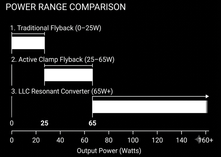
- Below 25W: Traditional flyback topology offers the best cost-performance ratio
- 25W to 65W: Active Clamp Flyback (ACF) balances efficiency and cost
- Above 65W: LLC resonant topology delivers clear advantages in efficiency and compact size
3. Core Structure of an LLC Resonant Converter
3.1 Where the Name “LLC” Comes From
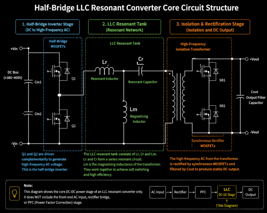
The name LLC comes directly from its three core resonant components: two inductors (L) and one capacitor (C):
- First L: Series Resonant Inductor (Lr): Stores energy and forms a series resonant loop with the resonant capacitor
- Second L: Magnetizing Inductor (Lm): Participates in the resonant process and helps create soft-switching conditions
- C: Resonant Capacitor (Cr): Works with both inductors to set the natural resonant frequency of the circuit
3.2 Six Core Modules of a Complete LLC Circuit
A full LLC resonant converter consists of six coordinated building blocks:
- Primary-side Switch Array: Usually MOSFETs or GaN power transistors, acting as high-speed switches
- LLC Resonant Network: Made of Lr, Lm and Cr — the heart of resonance and soft switching
- High-Frequency Isolation Transformer: Scales the voltage and provides electrical isolation between input and output
- Secondary-side Rectifier: Converts the high-frequency AC from the transformer into DC
- Output Filter: Smooths the output voltage and reduces ripple
- PFM Control IC: Adjusts switching frequency in real time to regulate output voltage and power
4. Basic Operating Principles of LLC
4.1 Resonance Explained Simply
Resonance works just like pushing a swing: if you push at exactly the right moment, a small force keeps the swing moving with large amplitude. This happens because the system has a natural oscillation frequency.
An inductor-capacitor pair behaves the same way: the inductor stores magnetic energy, the capacitor stores electrical energy, and they exchange energy back and forth periodically, creating a stable sinusoidal oscillation.
4.2 The Full LLC Operating Process
The energy conversion in an LLC converter happens in four steps:
- DC to High-Frequency Square Wave: The two primary switches alternate on and off, turning the input DC voltage into a high-frequency square wave
- Resonant Energy Transfer: The square wave enters the resonant network, where inductor-capacitor resonance shapes it into a smooth sinusoidal current, transferring energy efficiently through oscillation
- Voltage Transformation & Isolation: The sinusoidal current passes through the high-frequency transformer, stepping down the voltage while maintaining electrical isolation
- Rectified Output: The secondary rectifier converts the high-frequency AC back to DC, which is then filtered and delivered to the connected device
4.3 Voltage Regulation: PFM (Pulse Frequency Modulation)
Most conventional power supplies use PWM (Pulse Width Modulation), regulating output by changing how long the switch stays on. LLC uses PFM (Pulse Frequency Modulation), regulating output by changing how fast the switch operates:
- At the resonant frequency, the circuit runs at peak efficiency
- Below the resonant frequency, output voltage rises
- Above the resonant frequency, output voltage falls The control chip dynamically adjusts the switching frequency to maintain stable output across different load levels.
4.4 The Key to Soft Switching: Dead Time
A critical design element that makes soft switching possible is dead time.
The two primary switches can never be on at the same time — that would short-circuit the power supply. So between turning one switch off and turning the other on, there is a short gap where both switches are off: this is dead time. During this gap, the resonant current discharges the junction capacitance of the incoming switch, bringing its voltage down to nearly zero. Turning the switch on at zero voltage is what achieves Zero-Voltage Switching (ZVS).
4.5 Boundary Conditions for Stable Soft Switching
Soft switching does not work reliably under all conditions. It requires sufficient load power, a switching frequency close to the resonant frequency, properly tuned dead time, and accurate resonant component values. Outside these boundaries, soft switching breaks down and efficiency drops noticeably.
5. The Source of LLC Efficiency: Soft Switching Technology
5.1 Hard Switching vs. Soft Switching: Why Losses Differ
- Hard switching: Switching happens while voltage and current are both present. Transition losses are high, accompanied by significant heat and electromagnetic noise.
- Soft switching: Switching happens at either zero voltage or zero current. There is almost no extra loss during transition, and both heat and interference are greatly reduced.
5.2 ZVS (Zero-Voltage Switching)
ZVS works by discharging the voltage across the power transistor to nearly zero before it turns on. When the switch activates at near-zero voltage, almost no turn-on loss is generated.
ZVS acts mainly on the primary-side power transistors and is the primary mechanism by which LLC reduces heat and boosts efficiency.
5.3 ZCS (Zero-Current Switching)
ZCS works by timing the turn-off of rectifier devices so that current through them naturally falls to zero at the moment of switching. This eliminates reverse-recovery loss.
ZCS acts mainly on the secondary-side rectifiers, further reducing secondary-side losses and raising overall system efficiency.
5.4 Real-World Benefits of Soft Switching
For everyday users, soft switching delivers tangible improvements:
- Chargers run cooler even at full power, and do not get uncomfortably hot during long high-power charging sessions
- Higher conversion efficiency means less wasted energy and lower electricity use
- Lower electromagnetic interference means less disruption to nearby headphones, routers and other devices
- Reduced heat allows simpler cooling designs and smaller overall charger size
6. Side-by-Side Comparison: LLC vs. Other Mainstream Topologies
6.1 LLC vs. Traditional Flyback Converter
| Comparison Dimension | Traditional Flyback | LLC Resonant Converter |
|---|---|---|
| Energy Transfer Method | Inductor energy storage | Resonant oscillation |
| Switching Type | Hard switching / quasi-resonant | Full-range soft switching (ZVS + ZCS) |
| Typical Power Range | Below 25W low power | Above 65W medium-to-high power |
| Full-Load Efficiency | 88%–92% | 94%–96% |
| Size at Equal Power | Larger | Smaller |
| Component Cost | Low | Higher |
| Design Complexity | Low | High |
6.2 LLC vs. Active Clamp Flyback (ACF)
Active Clamp Flyback (ACF) is an improved flyback topology that also achieves soft switching. The key differences lie in technical approach and optimal power range:
- Technical approach: ACF is an enhanced flyback topology using PWM regulation; LLC is a standalone resonant topology using PFM frequency regulation
- Power fit: ACF offers the best cost-performance ratio from 25W to 65W; LLC shows clearer efficiency advantages above 65W
- Design & cost: ACF has a simpler structure and lower development cost; LLC requires more complex parameter tuning but reaches higher peak efficiency
6.3 Quick Guide to Three Topology Use Cases
- Below 25W low-power charging: Traditional flyback for maximum cost-effectiveness
- 25W–65W medium-power fast charging: Active Clamp Flyback (ACF) for balanced size, efficiency and cost
- Above 65W high-power fast charging: LLC resonance for the best combination of power density and efficiency
7. Real-World Applications of LLC in Fast Charging and Power Systems
7.1 Key Consumer Electronics Applications
- 65W+ smartphone fast chargers: 100W, 120W and 140W GaN chargers almost universally use LLC topology to balance power and compactness
- Laptop power adapters: Replace bulky traditional power bricks and greatly reduce travel weight
- Multi-port desktop and travel chargers: Maintain cool temperatures and high efficiency even when delivering high power across multiple ports
7.2 Applications Beyond Consumer Electronics
- Electric vehicle On-Board Chargers (OBC): Convert AC mains power to DC for the traction battery, where efficiency and reliability are critical
- Data center server power supplies: Run at full load continuously, where LLC’s high efficiency cuts long-term electricity and cooling costs significantly
- Industrial DC power supplies: Used in industrial equipment where stability, energy efficiency and long service life are strict requirements
7.3 Leading Industry Solutions
- Power Integrations (United States): Offers highly integrated LLC controller ICs with minimal external circuitry, widely used in consumer fast chargers
- Infineon (Germany): GaN power devices paired with dedicated LLC controllers, delivering excellent high-frequency performance for high-density chargers
- onsemi (United States): Mature and robust medium-to-high power LLC solutions, spanning consumer, industrial and automotive markets
7.4 The Industry Gold Standard: LLC Resonance + Synchronous Rectification (SR)
Modern high-power LLC chargers almost universally combine LLC resonance with synchronous rectification (SR). Traditional secondary-side rectification uses diodes, which have inherent forward voltage drop and cause extra loss.
Synchronous rectification replaces diodes with low-on-resistance MOSFETs, further cutting secondary-side losses and boosting overall efficiency by another 2%–3%. This combination is standard in today’s GaN fast chargers.
7.5 What Users Actually Notice
- At the same power rating, LLC chargers are smaller and lighter, making them more portable
- Case temperatures are noticeably lower during long full-power charging sessions
- There is barely any high-frequency whine at high power levels
- Higher conversion efficiency saves energy over long-term use
8. Advantages and Limitations of LLC Topology
8.1 Core Advantages
- High conversion efficiency: Full-load efficiency typically reaches 94%–96%, 2–3 percentage points higher than traditional flyback at high power, with meaningful energy savings
- High power density: Supports higher switching frequencies, which drastically shrinks the high-frequency transformer. Combined with reduced cooling requirements, this enables much smaller chargers
- Low electromagnetic interference: Smooth switching waveforms with minimal voltage/current spikes produce lower electromagnetic radiation, making it easier to meet international safety and EMC standards
- Wide input voltage range: Compatible with mains voltages around the world, making it suitable for global products
8.2 Inherent Limitations
- Reduced light-load efficiency: At very low power levels, stable soft switching becomes difficult and efficiency drops. The industry uses burst mode to improve light-load performance, but this adds control complexity
- High design barrier: Resonant parameters require precise tuning, including dead time, frequency range and component values, increasing development and engineering costs
- Poor cost competitiveness at low power: More components and a more sophisticated controller make LLC much more expensive than traditional flyback below 25W, so it offers no practical value at low power levels
9. Common Misconceptions and FAQs
9.1 Misconception: LLC is the same as GaN technology
This is the most common mix-up. LLC is a circuit topology; gallium nitride (GaN) is a power semiconductor material — they exist at completely different technical levels.
LLC can be built with traditional silicon MOSFETs or with GaN devices. GaN can also be used in flyback, ACF and other topologies. The two are often paired in high-power GaN chargers, but they are not the same thing.
9.2 Misconception: All high-power chargers use LLC
Topology choice depends on more than just power — cost targets and design goals also matter. Some budget high-power chargers use multi-winding flyback or other topologies to cut costs, even though they perform worse in efficiency, size and heat. LLC is an excellent solution for high-power fast charging, but not the only one.
9.3 Misconception: LLC chargers are bigger and heavier
The opposite is true. LLC runs at higher switching frequencies, which makes the high-frequency transformer much smaller. And because soft switching reduces heat, the heatsink can be smaller too. At the same power rating, an LLC+GaN charger is usually more compact and lighter than a traditional flyback charger.
9.4 Why are LLCs rare in low-power chargers?
LLC’s efficiency advantage only matters at medium and high power. At low power levels, switching loss is already a small fraction of total loss, so the efficiency gain from LLC is minimal. The extra components and design complexity actually raise cost significantly. For this reason, LLC is almost never used in chargers below 25W.
9.5 How reliable and durable are LLC chargers?
When designed properly with well-tuned resonant parameters, LLC chargers are at least as reliable as traditional topologies — often more so. Soft switching reduces voltage and current stress on transistors and generates less heat, slowing component aging and extending theoretical service life. Poorly designed units where soft switching frequently breaks down, however, can degrade faster.
10. Future Trends in LLC Technology
10.1 Deeper Integration with Wide-Bandgap Devices
Wide-bandgap semiconductors like gallium nitride (GaN) and silicon carbide (SiC) support higher switching frequencies and lower conduction losses. Combined with LLC topology, they will further boost power density and efficiency, driving even smaller charger designs.
10.2 Highly Integrated Single-Chip Solutions
Integrating LLC control, gate drive and even power switches into a single chip will greatly simplify external circuitry, lower development barriers and reduce bill-of-materials costs, allowing LLC to move down into lower-power consumer products.
10.3 Widespread Light-Load Efficiency Improvements
Smarter multi-mode operation and precise burst-mode control will continue to improve light-load and standby efficiency, reducing idle power consumption and meeting stricter global energy efficiency regulations.
10.4 Digital Control and Adaptive Frequency Tuning
Digital controllers replacing traditional analog designs will adjust operating parameters in real time based on input voltage and load, keeping efficiency optimal across the entire load range. This will better support complex multi-port, multi-protocol fast chargers.
10.5 Support for Higher-Power USB PD Standards
With USB PD 3.1 extending fast charging up to 240W, demand for higher-power consumer charging will keep growing. LLC topology will become the standard for high-power PD chargers, enabling even more powerful charging scenarios.
11. Summary: LLC From an Everyday User’s Perspective
At its core, the LLC resonant converter is the efficiency engine behind high-power fast charging.
Its logic is straightforward: it uses the natural resonance of inductors and capacitors, combined with carefully tuned dead time, to achieve soft switching and eliminate most switching loss. Paired with synchronous rectification to further cut secondary-side losses, it delivers high efficiency and low heat even at high power levels.
For everyday consumers, the most visible benefit of LLC is that chargers keep getting more powerful, yet smaller and cooler to the touch. Together with traditional flyback and active clamp flyback, LLC is driving charging technology toward greater efficiency, compactness and cool operation.