
Switch-Mode Power Supplies (SMPS) are the dominant power solution for modern electronics, from phone chargers to industrial power systems and EV charging stations. Think of them as the “smart energy manager” inside every device — far more efficient and compact than the old-fashioned linear power supplies they replaced. This guide breaks down SMPS fundamentals, core principles, circuit topologies, and key specifications with simple real-world analogies to make even technical concepts easy to grasp.
Quick Summary (1-Minute Read)
- Core Takeaway 1: An SMPS regulates power delivery by rapidly switching power semiconductor devices between fully on and fully off states — like a light switch flicking thousands of times per second. Paired with inductors, capacitors or transformers for voltage conversion and filtering, it achieves typical efficiencies of 80%–95% — far higher than traditional linear regulators.
- Core Takeaway 2: SMPS are categorized as isolated or non-isolated by electrical safety design, and fall into four main conversion types: AC-DC, DC-DC, DC-AC and AC-AC. Overall performance is determined by circuit topology, power semiconductors, control method and protection circuitry.
- Core Takeaway 3: Higher switching frequencies, soft-switching techniques and wide-bandgap semiconductors are the key drivers behind smaller, more efficient SMPS designs. A compliant product requires robust protection features and must meet safety, energy efficiency and electromagnetic compatibility (EMC) standards.
Beginner’s Guide: Basic Concepts
What Is a Switch-Mode Power Supply?
In simple terms, an SMPS converts incoming electrical power into a stable voltage or current output for end devices by rapidly toggling an electronic power switch on and off.
Everyday analogy: Think of it like a smart kitchen faucet. Instead of squeezing the pipe shut partway to reduce water flow (which wastes pressure), the valve fully opens and fully closes over and over, very quickly. The total amount of water you get depends on what fraction of the time the valve is open.
Its core operating principle is duty cycle control: by adjusting the fraction of time the switch stays on within each switching cycle, the system controls how much energy is delivered to the output side, ultimately achieving a regulated output voltage.
Why Are SMPS More Efficient?
The high efficiency of switch-mode power supplies comes directly from the operating state of the power switch:
- The switching device works almost entirely in two extreme states: when fully turned on, it has extremely low on-resistance and minimal conduction loss; when fully turned off, current drops to nearly zero and almost no power is dissipated.
- Power losses are concentrated only during the brief switching transitions. Unlike linear regulators, which waste excess power as heat to maintain a steady output, SMPS generate far less heat and are the foundational technology for compact power supply designs.
Everyday analogy: A linear power supply is like driving a car by keeping the gas pedal floored and riding the brake to control speed — it works, but it wastes tons of energy as heat. An SMPS is like tapping the gas on and off to maintain your speed: almost no energy is wasted, and the engine runs cool.
SMPS vs. Linear Power Supplies: Key Differences
| Feature | Switch-Mode Power Supply | Linear Power Supply |
|---|---|---|
| Regulation principle | Controls energy flow via high-speed switching | Dissipates excess power as heat to regulate voltage |
| Conversion efficiency | 80%–95%, energy efficient | Typically 30%–60%, low efficiency |
| Size & weight | Compact and lightweight | Bulky and heavy |
| Heat generation | Low heat output | Significant heat generation |
| Input voltage range | Supports wide input ranges | Narrow input voltage range |
| Output quality | Contains switching ripple and electromagnetic interference | Ultra-low ripple, very clean DC output |
Core Classifications of SMPS
By Electrical Isolation
- Non-isolated: No galvanic isolation between input and output; they share a common reference ground. Simple structure and low cost, used only for on-board conversion inside devices and extra-low-voltage applications.
- Isolated: Uses a high-frequency transformer to provide full electrical isolation between input and output — like two separate water pipes that transfer energy through a spinning wheel without touching. Meets electrical safety regulations and is the standard design for mains chargers and AC power adapters.
By Power Conversion Function
- AC-DC: Converts alternating current to direct current. The most common category, used in phone chargers, laptop adapters and built-in power supplies for consumer devices.
- DC-DC: Converts one DC voltage level to another, widely used for on-board voltage conversion inside electronic systems.
- DC-AC: Also known as an inverter. Converts direct current to alternating current, found in car power inverters and the inverter stage of UPS systems.
- AC-AC: Converts AC voltage magnitude or frequency, used for motor speed control and industrial drive systems.
By Modulation Method
- PWM (Pulse Width Modulation): Fixed switching frequency with adjustable on-time. Delivers consistent output ripple characteristics and is used in the vast majority of commercial power supplies.
- PFM (Pulse Frequency Modulation): Adjusts output by changing the switching frequency. Reduces switching cycles at light loads to cut losses, ideal for low-power standby applications.
Core Working Principles
The Foundation of Regulation: Volt-Second Balance
Volt-second balance is the fundamental theoretical principle behind all SMPS voltage regulation. In steady-state operation, the energy absorbed and released by the inductor over one full switching cycle is equal, so magnetic flux does not accumulate over time. Combined with closed-loop feedback control, this principle keeps the output voltage stable.
Everyday analogy: Think of the inductor as a water bucket with an inlet and an outlet. When the switch is on, water pours in; when the switch is off, water flows out to the load. Volt-second balance means the water added during the “on” phase exactly matches the water released during the “off” phase — so the water level (output voltage) stays perfectly steady, cycle after cycle.
Output voltage is jointly determined by the input voltage and the switch duty cycle.
Soft-Switching Technology: The Key to Higher Efficiency
Soft-switching techniques are designed to switch power devices when voltage or current is near zero, drastically reducing switching losses during transition events.
- Common implementations: Zero-Voltage Switching (ZVS), Zero-Current Switching (ZCS)
- Core benefits: Higher overall efficiency, reduced heat generation and support for much higher operating frequencies. A defining technology in high-end, compact power supply designs.
Everyday analogy: Hard switching is like slamming a door shut while people are still walking through — lots of impact, noise and wear. Soft-switching is like opening and closing the door exactly when the hallway is empty: no collision, almost no energy lost, and it can be done much faster without damage.
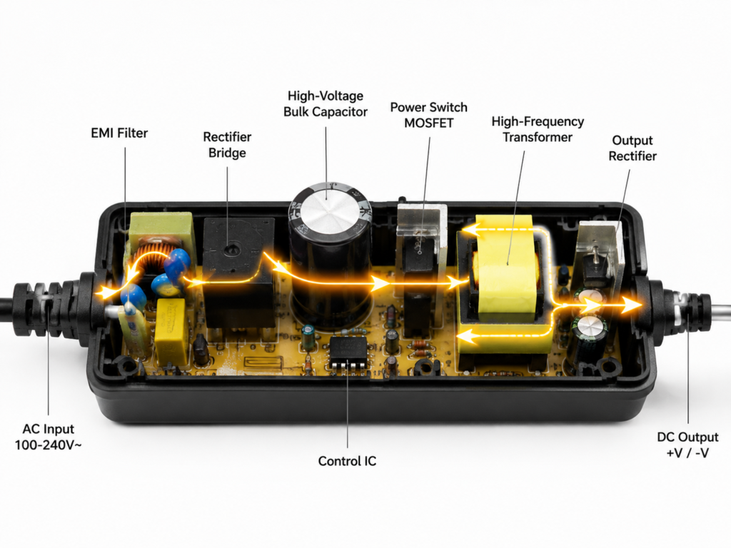
Full Operating Cycle of an AC-DC SMPS
A typical mains-input SMPS follows a seven-stage power flow:
- Input Filtering: Incoming power first passes through an EMI filter network, which suppresses grid interference from entering the device and prevents internal switching noise from flowing back into the mains supply.
- Rectification: A rectifier bridge converts line-frequency alternating current into unregulated pulsating direct current.
- Bus Energy Storage: A high-voltage bulk capacitor smooths the pulsating DC into a stable high-voltage DC bus — like a water reservoir that evens out surges and dips.
- High-Frequency Chopping: The control IC drives power switches on and off at high speed, chopping the high-voltage DC into a stream of high-frequency pulses.
- Energy Conversion: A transformer or inductor transfers energy, performs voltage level conversion and provides electrical isolation.
- Output Filtering: The output side rectifies and filters the high-frequency waveform to remove switching ripple, producing clean low-voltage DC.
- Closed-Loop Feedback: A feedback circuit continuously samples output voltage and current, dynamically adjusting the switch duty cycle to maintain precise voltage regulation — like a thermostat that turns the heater on and off to keep a room at the right temperature.
Common SMPS Topologies Explained
The circuit topology defines an SMPS’s power rating, efficiency profile and ideal use cases. Below are the most widely adopted designs in the industry.
Three Basic Non-Isolated Topologies
- Buck (Step-Down) Converter: Only produces an output voltage lower than the input. Simple structure, high efficiency and the most widely used step-down solution — like rolling a cart downhill, you only need to control the speed, not push.
- Boost (Step-Up) Converter: Only produces an output voltage higher than the input. Features continuous input current and favorable EMI characteristics, commonly used for LED drivers and battery boost circuits — like pumping water uphill to a higher tank.
- Buck-Boost (Step-Up/Step-Down) Converter: Maintains a stable output even when input voltage varies above and below the target output. Traditional designs have inverted output polarity; modern four-switch architectures deliver non-inverting buck-boost operation, ideal for battery-powered devices with wide input ranges — like a car that can drive both uphill and downhill while keeping the same speed.
Main Isolated Topologies
- Flyback Converter: Typically used for low-power applications from 1W to 65W, with optimized designs extending to around 100W. Simple and low-cost, it is the most common topology for smartphone chargers, small appliance power supplies and standby auxiliary power.
- Forward Converter: Suited for power levels from 100W to 1kW. Features low output ripple and strong load capability, widely used in industrial control and telecommunications equipment.
- Half-Bridge / Full-Bridge: Designed for medium to high-power applications. High power capability, balanced switch stress and excellent reliability. Found in desktop PC power supplies, DC charging stations and industrial equipment.
- LLC Resonant Converter: Achieves extremely low switching losses through inherent soft-switching operation. Used in medium-to-high power, high-efficiency designs such as TV power supplies, server power supplies, premium adapters and on-board chargers for electric vehicles.
Core Components & Key Technologies
Key Building Blocks of an SMPS
A switch-mode power supply consists of three main functional blocks:
- Input Front-End: EMI filter network, rectifier bridge and high-voltage bulk capacitor. Handles noise suppression, AC-to-DC rectification and bulk energy storage.
- Power Stage: Power switching devices (MOSFETs / GaN transistors), magnetic components (transformer / inductor) and output rectifiers. Performs the actual power conversion.
- Control Stage: Main control IC and sampling/feedback circuitry. Adjusts duty cycle in real time to implement closed-loop regulation and system protection.
PFC (Power Factor Correction)
PFC shapes the input current waveform to reduce harmonic pollution on the power grid and improve overall power utilization, helping products meet mandatory regulatory requirements.
- Passive PFC: Simple structure and low cost, with moderate correction performance. Used in entry-level, low-power supplies.
- Active PFC: Delivers excellent power factor correction and supports wide global input voltage ranges. Standard on mid-to-high-end power supplies. Generally, AC-DC supplies above 75W require PFC to comply with harmonic emission standards in most markets.
Everyday analogy: Without PFC, current rushes into the power supply in short, sharp spikes — like a crowd all trying to squeeze through a single door at the same time. PFC spreads the current evenly across the full AC cycle, like an orderly single-file line. It doesn’t change how many people get through (total power used), but it’s far easier on the “doorway” (the power grid) and causes much less disruption.
Essential Protection Features
A reliable SMPS includes comprehensive protection mechanisms to safeguard both the power supply itself and connected loads:
- Over-Voltage Protection (OVP): Automatically shuts down if output voltage exceeds safe limits, protecting downstream electronics.
- Under-Voltage Protection (UVP): Ceases operation if input voltage drops too low, preventing component damage from overcurrent conditions.
- Over-Current / Short-Circuit Protection (OCP / SCP): Cuts output power if current exceeds ratings or a short circuit occurs, preventing catastrophic failure.
- Over-Temperature Protection (OTP): Reduces output power or shuts down completely if internal temperature rises too high, improving long-term reliability.
- Surge Protection: Defends against transient grid surges and lightning-induced voltage spikes.
Key Specifications & Applications
Must-Know Specifications for Beginners
- Input Voltage Range: A wide 85–265V input rating supports global mains voltages for maximum worldwide compatibility.
- Output Rating: Rated output voltage and maximum output current, which together define the supply’s power delivery capability.
- Conversion Efficiency: The ratio of output power to input power. Higher efficiency means less wasted energy and lower heat generation.
- Ripple & Noise: Unwanted AC interference superimposed on the DC output. Lower values indicate cleaner, more stable power delivery.
Common Application Scenarios
- Consumer Electronics: Smartphone chargers, laptop power adapters, built-in power supplies for TVs and monitors.
- Industrial Sector: Industrial control power supplies, LED drivers, power for test and measurement instruments.
- New Energy Systems: DC fast charging stations, on-board vehicle chargers, photovoltaic inverters.
Frequently Asked Questions
Will SMPS output ripple damage my devices?
Output ripple on certified, compliant products stays within industry standard limits and will not damage electronics during normal everyday use. Only specialized applications such as high-fidelity audio equipment or high-precision analog instrumentation require additional low-ripple filtering stages.
Why are GaN chargers so much smaller?
Gallium Nitride (GaN) semiconductors have far lower switching losses than traditional silicon devices, allowing power supplies to operate at much higher switching frequencies. Higher frequencies reduce the required size of transformers, capacitors and other passive components, resulting in dramatically higher power density in a smaller form factor.
Everyday analogy: Think of a warehouse that sorts packages. If your sorting machine runs twice as fast, you don’t need as many storage bins or as much floor space to handle the same number of packages per day. GaN is that faster sorting machine — it lets engineers shrink the “warehouse” (transformers, capacitors) while delivering the same total power.
Does a higher power factor mean lower electricity bills?
For residential users, a higher power factor does not directly reduce your electricity bill. Its primary benefit is reducing harmonic pollution and improving overall grid efficiency. For industrial and commercial customers, meeting required power factor thresholds can avoid utility penalty charges.
Are isolated power supplies always better than non-isolated ones?
Not universally. External power supplies connected directly to the mains must use isolated designs to ensure electrical safety. For on-board voltage conversion inside devices, non-isolated designs offer higher efficiency and lower cost. The optimal choice always depends on the specific application and safety requirements.
Conclusion
Thanks to their high efficiency, compact size and wide input flexibility, switch-mode power supplies have fully replaced traditional linear regulators as the standard power solution for modern electronics. As wide-bandgap semiconductors like GaN and SiC become more widespread, alongside ongoing advances in soft-switching and high-frequency design, SMPS will continue to deliver higher power density and better efficiency across an ever-broader range of applications.