
If you’ve ever wondered why a cheap USB-C cable works fine for charging but drops connections when transferring files or driving a 4K monitor, the answer often comes down to impedance. It’s one of the most important specs for high-speed cables, yet almost no consumer product listings mention it — and most people have no idea what it means.
The first and biggest misconception almost everyone has: impedance is not the same as regular electrical resistance you measure with a multimeter. This guide breaks down cable impedance in plain English, covers the types you’ll actually encounter, what affects it, and why it makes such a big difference for USB-C, HDMI, Ethernet, and more.
Think of impedance like the consistent width of a road for electrical signals. If the road suddenly narrows or widens, traffic bounces back and slows down. For high-speed data and video signals, consistent impedance is what keeps the signal clean, reliable, and running at full speed.
1. The Basics: What Is Cable Impedance?
1.1 Definition & Physical Meaning
When people talk about impedance in cables, they almost always mean characteristic impedance.
- It describes the total opposition a uniform transmission line presents to an electrical signal. It is determined by the cable’s resistance, inductance, capacitance, and dielectric properties, and is an inherent electrical property of the cable itself.
- It plays a key role in signal integrity, and strongly affects signal reflection, attenuation, and propagation speed.
- Critical clarification: Characteristic impedance is not the same as DC resistance. You cannot measure it with a basic multimeter, and it does not increase with cable length. This is the single most commonly searched beginner question about cable impedance.
1.2 Why Impedance Matters
When impedance stays consistent and properly matched across the whole connection, you get:
- Less signal reflection, so nearly all signal energy reaches the receiver instead of bouncing backward.
- Better high-speed signal integrity, reducing distortion and preventing degraded signal quality.
- Fewer bit errors and more reliable data transmission.
- Proper interoperability between the transmitter, cable, and receiver, as required by official interface standards.
1.3 Standard Impedance Values by Interface
There is no single “best” impedance number. Each standards body selects a target value based on transmission method, signal quality requirements, and system design tradeoffs.
These are the values you will see most often in consumer and industrial electronics:
| Standard Impedance | Most Common Use Case |
|---|---|
| 50 Ω | RF systems, radio equipment, test and measurement gear |
| 75 Ω | Cable TV, satellite, and coaxial video distribution |
| 90 Ω differential | USB 2.0 high-speed differential pairs |
| 85 Ω differential | USB4 high-speed links |
| 100 Ω differential | Ethernet twisted pair, HDMI |
| 120 Ω differential | RS-485, CAN and other industrial field buses |
2. The Main Types of Cable Impedance
2.1 Characteristic Impedance
- Definition: The ratio of voltage to current on an infinitely long, uniform transmission line. It depends only on the cable’s physical geometry and the materials used — it does not change with cable length.
- Typical values: 50 Ω or 75 Ω for coaxial cables, 100 Ω for standard twisted-pair cable.
2.2 Single-Ended Impedance
- The impedance of a single conductor measured relative to a reference ground. It is the building block for calculating differential impedance.
- Most commonly seen in coaxial cables and single-ended signal circuits.
2.3 Differential Impedance
- The total impedance between the two wires in a differential signal pair. This is the key parameter for almost all modern high-speed digital interfaces.
- Almost all high-speed standards require tightly controlled differential impedance. For example, USB 2.0 differential pairs target 90 Ω, and HDMI differential pairs are designed around 100 Ω.
- To maintain consistent differential impedance, manufacturers must strictly control the spacing between the two conductors and the thickness of the insulation along the entire length of the cable.
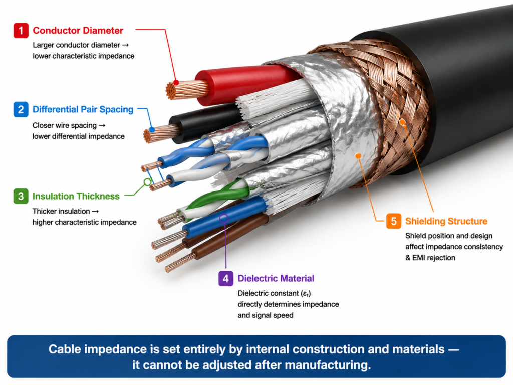
3. Key Factors That Determine Cable Impedance
Impedance is set entirely by the cable’s physical construction and materials. It is not something you can adjust or upgrade after manufacturing.
3.1 Physical Geometry
- Conductor diameter: Increasing conductor diameter generally lowers characteristic impedance, assuming all other physical dimensions remain unchanged.
- Conductor spacing: For differential pairs, the closer the two wires sit to each other, the lower the differential impedance.
- Insulation thickness: Thicker insulation around the conductors results in higher characteristic impedance.
- Shielding structure: The design and position of the shield also affect impedance consistency, while also reducing external electromagnetic interference (EMI).
3.2 Material Properties
- Conductor material: The conductivity of copper, aluminum, or other metals affects high-frequency signal loss, rather than changing the base impedance value directly.
- Dielectric material: The insulation material (PVC, FEP, PE, etc.) has a property called dielectric constant (εr). This determines how fast the signal travels and how much capacitive reactance the line has, which directly impacts impedance.
3.3 Frequency & the Skin Effect
At high frequencies, electrical current stops flowing evenly through the entire conductor. Instead, it travels mostly along the outer surface of the copper. This is called the skin effect.
- It reduces the effective cross-sectional area of the conductor, increasing AC resistance and signal loss.
- The higher the frequency, the thinner the “skin” of current. Silver-plated conductors can reduce high-frequency conductor loss for very high-speed applications.
- Important note: Braided shielding is for reducing electromagnetic interference (EMI). It does not fix or reduce skin effect losses.
4. How Cable Impedance Is Measured
Characteristic impedance cannot be measured with a standard multimeter. It requires specialized test equipment, typically used in engineering and manufacturing.
4.1 Common Measurement Methods
- Time-Domain Reflectometry (TDR): Sends a fast electrical pulse down the cable and analyzes the reflected signal. It shows how impedance changes along the length of the cable, so engineers can spot dips or spikes — most often found at connectors or damaged sections.
- Vector Network Analyzer (VNA): Tests signal performance across a range of frequencies to measure loss and reflection characteristics. From this data, engineers calculate impedance and signal loss behavior.
4.2 Practical Measurement Notes
- Professional lab testing always includes calibration to remove the influence of test fixtures and adapters, so results reflect only the cable itself.
- Bending, twisting, or stretching a cable changes its internal geometry and shifts impedance. Tests are always performed with the cable laid straight and unstressed.
5. Impedance Matching & Performance Optimization
5.1 The Core Rule of Impedance Matching
For the cleanest signal, the source, the cable, and the load (receiver) must all share the same characteristic impedance.
- When impedance does not match, part of the signal reflects back toward the source.
- Mild mismatches cause signal distortion and higher error rates.
- Severe mismatches can prevent a high-speed link from establishing reliably, cause frequent dropouts, or force the connection to fall back to a lower speed.
5.2 Common Ways to Improve Matching
- Termination resistors: Series or parallel resistors added at the source or load end absorb reflected energy and match the line impedance.
- Smooth impedance transitions: Avoid abrupt changes in wire diameter or structure; design gradual, tapered transitions instead.
- Controlled geometry in connectors: Connector and transition areas are carefully engineered to keep impedance as continuous as possible, since connectors are the most common source of impedance dips and spikes.
5.3 Design & Buying Recommendations
- Use the correct standard impedance for your use case: 50 Ω for RF systems, 75 Ω for coaxial video, ~100 Ω for Ethernet twisted pair, and the specified differential impedance for USB, HDMI, DisplayPort and other high-speed interfaces.
- For off-the-shelf cables, always choose products built to the official interface standard impedance.
- For custom cables, specify conductor size, dielectric material, and construction tolerances to ensure consistent impedance along the entire link.
6. Why Are There So Many Different Standard Impedances?
Newcomers often ask why we don’t just pick one number for everything. Each value was chosen for a specific engineering tradeoff:
- 50 Ω: A balanced sweet spot between power handling and low signal loss, making it the default for RF and test equipment.
- 75 Ω: Optimized for lower signal attenuation over long distances, which makes it ideal for cable TV and broadcast video.
- 90 Ω differential: Selected for USB high-speed links based on system-level design tradeoffs for cost, signal quality, and connector size.
- 100 Ω differential: The standard for twisted-pair Ethernet and HDMI, well suited for balanced pair cable construction.
- 120 Ω differential: The common target for industrial buses like RS-485 and CAN, chosen for robust performance in noisy factory environments.
7. Common Impedance Myths Debunked
Myth 1: Impedance is just resistance, and longer cables have higher impedance
False. DC resistance increases with length, but characteristic impedance does not. On a well-made uniform cable, impedance stays consistent regardless of length, because it is determined by construction and materials.
Myth 2: Lower impedance is always better
False. What matters is matching the standard value for your interface. A cable with the wrong impedance — even if it’s “lower” — will cause reflections and worse performance. For USB, 90 Ω differential is the correct target, not higher or lower.
Myth 3: If a cable charges fine, its impedance is fine
False. Charging only uses DC power, which is not affected by characteristic impedance. A cheap cable can work perfectly for charging while having very poor impedance control, causing failures at high data speeds or high-resolution video.
Final Summary
- When talking about high-speed cables, “impedance” almost always means characteristic impedance. It describes how the cable interacts with electrical signals, and it is determined by the cable’s internal construction and materials.
- Differential impedance is the key specification for modern USB-C, HDMI, DisplayPort, and Ethernet cables. Each standard has its own required target value.
- Impedance must be consistent and matched across the source, cable, and receiver. Mismatches cause signal reflection, data errors, and dropped high-speed connections.
- High-speed USB-C cables (with USB 2.0 High Speed targeting 90Ω differential, and USB4 links following their own specified impedance targets) require tight impedance control, which is why properly built USB-C cables have a far more complex internal structure than basic charge-only cables.
- Cheap cables often skip tight impedance control. They may work for basic charging, but they will struggle or fail at high data speeds and high-resolution video. Choosing certified, standards-compliant cables ensures proper impedance and reliable high-speed performance.