
Nowadays, USB-C PD chargers are everywhere, powering everything from smartphones to laptops. But many older devices still use barrel-jack DC power and do not support the USB PD protocol, so they cannot get the right voltage from a PD charger on their own. That is exactly what USB PD triggers are designed to solve.
1. What is a USB PD Trigger?
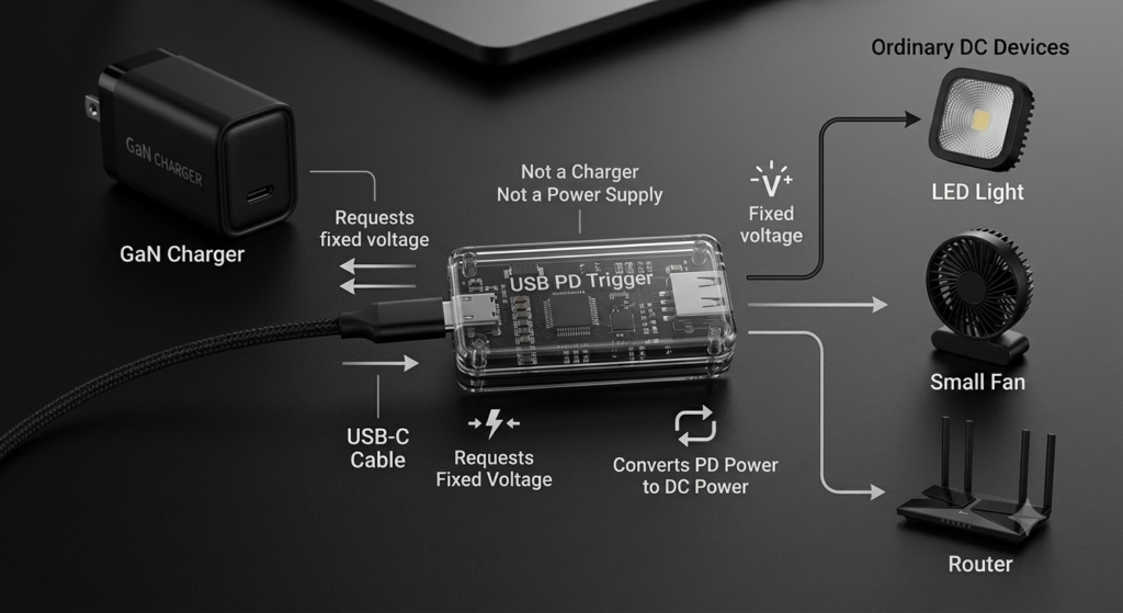
1.1 Definition of USB PD Trigger
A USB PD Trigger, also known as a PD decoy or PD power take-off module, is a small electronic device that simulates PD communication to request a specific output voltage from a USB PD charger.
It is called a “trigger” because it does not generate power itself — it simply triggers the charger to switch from its default 5V output to a higher target voltage, acting as both a voltage switch and a protocol translator. In the broader USB PD ecosystem, it serves as an adapter bridge: one end connects to a standard PD charger, the other to a regular DC device, allowing non-PD devices to use PD power sources.
1.2 Understanding PD Triggers in One Sentence
Many people confuse them with chargers or power supplies. Here is the clear distinction:
- It is not a charger: it cannot convert AC to DC, and has no independent charging functionality
- It is not a power source: it generates no electricity; all power comes from the upstream PD charger
- It is essentially a request tool: it helps devices apply for a fixed voltage from the PD charger, converting PD power into standard DC power for general use.
1.3 Common Names
You will see it referred to by many names, but they all describe the same product:
- USB PD Trigger
- PD Decoy
- PD Trigger Board
- PD Power Module
- USB-C PD Trigger Board
2. Why Do USB PD Triggers Exist?
2.1 USB PD Defaults to 5V Output
Per USB-C specification, the interface only outputs a default 5V until PD protocol negotiation is complete. This is a safety feature to prevent high voltage from damaging devices that do not support it. In other words, even a 100W PD charger will only output 5V before a successful handshake.
2.2 Many Devices Do Not Support USB PD Communication
Countless common devices have no PD communication chip inside — they cannot “talk” to the charger, so they never receive higher voltage. Examples include:
- Older routers, security cameras and speakers with DC barrel jacks
- LED strips and small fans
- DIY electronics projects and microcontroller development boards
- Industrial control modules and sensors
These devices only accept fixed-voltage DC power. Plugging them directly into a PD charger only delivers 5V, so they will not operate properly.
2.3 What Problems Do PD Triggers Solve?
The core value of a PD trigger is to automatically handle the PD handshake on behalf of these “non-communicative” devices, successfully request the target voltage, and convert USB-C PD power into standard DC output. Simply put, with one, your existing PD charger can power all kinds of older DC devices — no need to buy a pile of dedicated power adapters.
3. How Does a USB PD Trigger Work?
3.1 USB PD Communication Flow
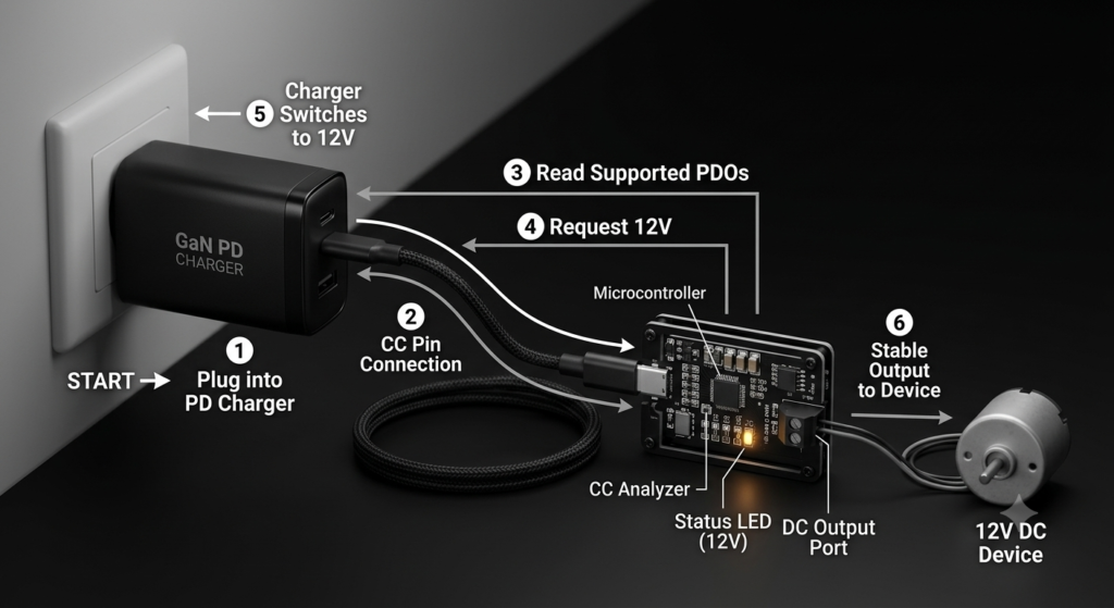
The entire negotiation process is very fast, completing in a split second after power is applied:
- When the PD trigger is plugged into a PD charger, the CC pins on the USB-C connector establish a connection and confirm both sides support the PD protocol
- The trigger reads all voltage levels supported by the charger (called PDOs, or Power Delivery Objects)
- The trigger requests the selected voltage level from the charger according to its settings
- The charger confirms the request, switches its output voltage, and delivers stable power to the downstream device
3.2 Internal Components of a PD Trigger
A basic PD trigger has a simple structure:
- USB-C connector: for connecting to the PD charger
- PD protocol chip: the core component that handles PD communication and voltage requests
- Voltage selection module: for setting the desired output voltage
- DC output port: for connecting to the powered device
- Status indicator: shows operating state and current voltage level
Higher-end models may also include an MCU (microcontroller unit) to enable programmable features and fine voltage adjustment.
3.3 Complete Workflow
Taking a 12V request as an example, the full process is:
PD Charger → connected via USB-C cable → PD Trigger → PD protocol negotiation completes → trigger requests 12V → charger switches to 12V output → downstream device operates normally.
4. What Voltages Can a PD Trigger Request?
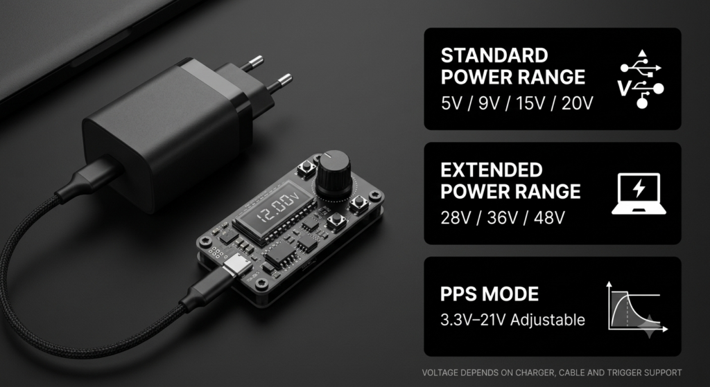
The voltages a PD trigger can actually deliver depend on both the charger and the trigger itself, falling into three main categories.
1. USB PD Standard Power Range (SPR)
This is the most common standard, supported by nearly all PD chargers, with four fixed voltage levels:
- 5V (the default, available on every USB-C port)
- 9V
- 15V
- 20V
Note that not every charger has all four levels. A low-power phone charger may only have 5V and 9V, while laptop chargers usually have all four. Which levels are available depends on the charger’s PDO list.
2. USB PD 3.1 Extended Power Range (EPR)
Added in the PD 3.1 specification, EPR supports much higher voltages with a maximum power of 240W:
- 28V
- 36V
- 48V
To use these high voltages, two conditions must be met: the charger must be PD 3.1 EPR rated, and the trigger itself must also support the EPR protocol. Both are required.
3. PPS Mode
PPS stands for Programmable Power Supply. It allows fine, continuous voltage adjustment over a range — for example, from 3.3V to 21V in 0.02V steps — and is mainly used for smartphone fast charging.
Basic fixed-voltage PD triggers generally do not support PPS mode. Triggers with PPS support are usually programmable models with an MCU, intended for development and testing, and are rarely needed by regular users.
5. What Types of PD Triggers Are There?
Based on operation and features, PD triggers on the market fall into four main categories.
1. Fixed-Voltage Type
This is the simplest and most common type. Voltage is selected via solder pads, jumper caps, DIP switches or configuration resistors.
They are low-cost, highly reliable, and stay set once configured, making them ideal for DIY projects and long-term powering of fixed devices.
2. Button-Switch Type
These triggers have a built-in button and status display (LED lights or a digital screen). Press the button to switch voltage levels — no soldering or DIP switches required.
Their main advantage is flexibility: one module can work with devices of different voltages. They are great for regular users who switch between devices often.
3. Auto-Detect Type
These triggers require no manual setup. On power-up, they automatically request the highest voltage the charger supports; some can also detect the downstream device’s requirements.
They are hassle-free and perfect for integrated products or built-in installations. The downside is that you cannot freely choose the voltage.
4. Programmable Type
These are the most feature-rich models, with an onboard MCU. Voltage can be configured via PC software, and they support communication interfaces like UART and I²C. Some also support PPS adjustment.
They are mainly used for engineering development, product testing and lab validation — not typically needed for everyday home use.
6. What Interfaces Do PD Triggers Have?
1. Input Connectors
Input is almost always USB-C, in two form factors:
- USB-C female socket: requires a separate USB-C cable to connect to the charger
- USB-C male plug: plugs directly into the charger, no extra cable needed
2. Output Connectors
There are many output options to match different devices:
- DC barrel jack: the most common, fits most older DC devices
- DC pins / header pins: for DIY soldering and breadboard testing
- Type-C output: for powering USB-C devices directly
- XT30 / XT60: common for RC hobby and high-power devices
- Screw terminals: for industrial equipment and high-current setups
3. Common Form Factors
By size and packaging, they come in three main styles:
- Bare PCB boards: compact, great for embedding and DIY projects
- Cased modules: enclosed in a protective shell, safer for everyday use
- Industrial modules: DIN-rail mountable, wide temperature range, for industrial environments
7. What Are the Use Cases for USB PD Triggers?
PD triggers are extremely versatile, useful for everything from personal DIY to industrial settings.
1. DIY Electronics Projects
This is the classic use case for PD triggers. When building Arduino, ESP32, Raspberry Pi or STM32 projects, you do not need a dedicated power supply. Just use your existing PD charger plus a trigger to get the voltage you need.
Note: always confirm your board’s rated voltage and power requirements before powering it on to avoid damage.
2. Industrial Equipment
Many PLC peripherals, industrial control boards, sensors and automation equipment run on DC power. Using PD triggers with PD chargers simplifies power setups and reduces the number of dedicated power supplies needed.
3. Home Devices
Lots of small home devices work great with them: 12V LED strips, small fans, security cameras, old routers, desktop speakers and more. With a PD trigger, you can retire your pile of dedicated adapters and use one PD charger for everything.
4. Testing and Repair
For electronics repair, lab development and product validation, a PD trigger works as a compact variable DC power source. You can quickly get different voltages for testing equipment, without needing a bulky bench power supply.
8. Important Notes When Using USB PD Triggers
PD triggers are easy to use, but there are a few critical points to follow to avoid damaging equipment.
1. Voltage Must Match Exactly
This is the most important rule: you may only request the exact voltage your device is rated for.
For example, a 12V router must only be supplied with 12V. Never apply 20V to a 12V device — overvoltage will instantly destroy the device, and may even create a fire hazard.
2. Power Must Be Sufficient
The charger’s output power must be greater than or equal to the total power draw of your device.
Calculating power is simple: Power (Watts) = Voltage (Volts) × Current (Amps)
For example, if your device is 12V 2A, that is 24W. The charger must be able to deliver at least 24W at 12V. Insufficient power will cause unstable operation, random restarts, or even damage the charger.
3. Confirm Charger Supports the Target Voltage
Not all PD chargers have every voltage level. Many phone PD chargers only have 5V and 9V, with no 15V or 20V.
Before buying a trigger, check what PDOs your PD charger supports to make sure it has the voltage you need.
4. Cable Compatibility
Not every USB-C cable works for high-power scenarios:
- For 3A and lower, most USB-C cables will work
- For 5A and higher, you must use a USB-C cable with an E-Marker chip
An underrated cable will prevent the charger from delivering full power, and may trigger protection and shut down.
5. EPR Usage Requirements
If you need 28V, 36V or 48V EPR voltages, all three components must support it:
- A PD 3.1 EPR charger
- An EPR-capable USB-C cable
- A PD trigger that supports the EPR protocol
Missing any one means you will not get the high-voltage output.
9. Common Misconceptions About USB PD Triggers
There are many misunderstandings about PD triggers. Here are the most common ones clarified.
Misconception 1: PD triggers increase a charger’s power
False. A PD trigger only requests voltage. It cannot generate power, and it cannot increase the charger’s rated output.
Whatever the charger’s maximum output is, that is the limit. The trigger can only select from the charger’s existing capabilities — it cannot turn a 65W charger into a 100W one.
Misconception 2: All USB-C chargers support PD
False. Many cheap USB-C chargers only have a C-shaped connector but no PD protocol chip inside. They always output 5V and nothing else.
A PD trigger will not help with these — you will never get higher voltage.
Misconception 3: PD triggers make any device fast-charge
False. The core purpose of a PD trigger is power delivery, not fast charging.
It simply provides the correct DC voltage to a device. It will not add fast charging to a device that does not support it. Phone fast charging requires negotiation between the phone and charger — a trigger cannot replace that.
Misconception 4: All PD triggers support 20V
False. The maximum voltage a trigger supports depends on its hardware design and protocol chip.
Some cheap triggers only go up to 9V or 15V. Always check the specs before buying to make sure it supports your required voltage.
Misconception 5: PD triggers support 240W
False. 240W is the maximum of the PD 3.1 EPR specification, and only purpose-built EPR triggers can achieve it.
The vast majority of regular PD triggers max out at 20V / 100W SPR standard, and cannot reach 240W at all.
10. Summary
1. Key Knowledge Recap
A USB PD trigger is a PD protocol adapter module. It communicates with a PD charger over the CC pins to request a specific voltage level, allowing non-PD DC devices to use PD chargers.
They come in four main types: fixed-voltage, button-switch, auto-detect and programmable. Standard models support 5V/9V/15V/20V, while premium EPR models support 28V/36V/48V. They are widely used in DIY projects, home devices, industrial power, and testing & repair.
2. Advice for Regular Consumers
- Confirm device specs first: know exactly what voltage, current and total power your device needs, then choose a trigger that matches.
- Choose reliable products: prefer products with full protocol support, clear spec labeling, and built-in over-current, over-temperature and over-voltage protection. Avoid ultra-cheap unbranded boards.
- Verify full compatibility for high voltage: if you need 28V, 36V or 48V, make sure your charger, cable and trigger all support USB PD 3.1 EPR.