
USB-C is the slim, reversible connector that has taken over nearly every modern gadget — from phones and laptops to chargers and monitors. Yet most people never stop to wonder: how does such a tiny plug handle charging, data transfer, video output, and more, all at once?
Think of a USB-C port as a compact, multi-purpose smart transportation hub. A classic USB-A port is like a single-lane dirt road that only carries small loads one way. USB-C, by contrast, is a full, symmetric multi-lane hub: it has dedicated power pipelines, high-speed data highways, a central control tower, and backup side lanes, all laid out in a mirrored design so the plug works perfectly no matter which way you flip it.
This guide breaks down every part of the USB-C interface in plain language, with simple, consistent analogies. No engineering background is required.
1. Physical Structure & Design Features
1.1 Shape, Size & Reversible Design
- USB-C uses a 24-pin fully symmetric layout, which is what enables its signature blind-plug, reversible functionality — no more fumbling to plug it in the “right way.”
- Its compact form factor measures roughly 8.4mm × 2.6mm: slim enough for thin smartphones and ultra-light laptops, while still robust enough for high power and high-speed signaling.
- Analogy: It is like a perfectly symmetric keycard that works identically on both sides. You never have to check which side faces up; every contact pad lines up with its matching counterpart either way.
1.2 Metal Shell & Shielding Layer
- The outer metal housing provides EMI (electromagnetic interference) shielding, blocking external electrical noise from corrupting high-speed signals.
- An inner stainless steel / zinc alloy frame reinforces the connector, giving it high durability to withstand thousands of insertions and removals.
- Analogy: The metal shell acts like a soundproof, reinforced tunnel around all the internal wires. It keeps outside electrical “noise” from interfering with signals, and the strong inner frame prevents the port from wearing out even with years of daily plugging and unplugging.
1.3 Internal Pin Layout
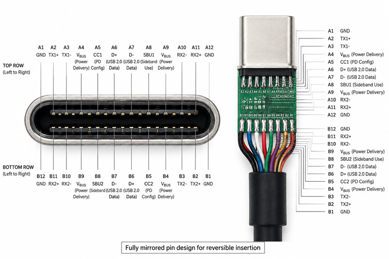
- Inside the connector, there are two rows of 12 pins each (24 total), arranged in a perfect mirror-image layout top and bottom.
- This set includes power pins (VBUS), ground pins (GND), configuration channel pins (CC), sideband use pins (SBU), USB 2.0 data pins (D+/D-), and high-speed differential signal pairs (TX/RX).
- Analogy: Imagine two identical floors of a terminal building, one above the other. Every gate and pipeline on the top row has an exact duplicate on the bottom row. Whichever way you plug in the cable, all functions connect to their matching counterparts automatically.
2. Pin Definitions & Core Functions
Every pin inside USB-C has a dedicated job. Sticking with the transportation hub analogy:
2.1 Power Pins (VBUS / GND)
- VBUS is the main power delivery line. In standard USB PD (SPR mode), it carries between 5V and 20V. Under the EPR extended power specification, it can support up to 48V.
- GND is the current return path, completing the electrical circuit. Together with VBUS, it enables dynamic voltage and current adjustment via the USB PD protocol.
- Maximum power capability reaches 240W under EPR (48V / 5A), when used with a full EPR-compliant cable and device ecosystem.
- Analogy: VBUS is the main supply pipeline carrying energy to your device, and GND is the return pipeline. Upgrading from SPR to EPR is like upgrading from a regular water main to a high-capacity fuel pipeline — it can deliver far more power for larger devices like gaming laptops and workstations.
2.2 Configuration Channels (CC1 / CC2)
- These two pins detect which orientation the cable is plugged in, and negotiate the power role: Source (power provider), Sink (power receiver), or DRP (dual-role).
- They carry all USB PD communication messages, and also read capability information from e-Marker chips inside cables.
- Analogy: CC1 and CC2 are the port’s control tower and customs checkpoint rolled into one. First, they detect which direction the cable “ship” is arriving from. Then they negotiate who is supplying power and who is receiving it. They also check the cable’s “ID card” (e-Marker) to confirm how much power and speed it can safely handle. All instructions for power levels and alternate modes flow through these two pins.
2.3 Data Pins (D+/D- & SBU)
- D+ / D-: The classic USB 2.0 data pair, responsible for low-speed, full-speed and high-speed (480Mbps) USB 2.0 data transfer. Only one functional USB 2.0 pair is used; the mirrored set exists purely for reversibility.
- SBU (Sideband Use): Auxiliary sideband pins. They can carry the AUX channel for DisplayPort Alt Mode, or be used for debug communication. Older analog audio modes over SBU have been largely phased out.
- Analogy: D+/D- is the paved local road that always works — it is slower, but universally compatible for basic file transfers and peripherals. SBU pins are the side access roads: they sit idle most of the time, but can be repurposed for special jobs like auxiliary video signals or diagnostic access when needed.
2.4 High-Speed Differential Signals (TX / RX)
- There are 4 high-speed differential pairs total (2 transmit + 2 receive pairs), supporting full-duplex communication. The speed of each pair depends on the active protocol.
- These pairs are multi-purpose: they can carry USB 3.x data, DisplayPort video, PCIe signals and more.
- When all 4 pairs are fully utilized, they enable the symmetric 40Gbps+ bandwidth of USB4 and Thunderbolt.
- Analogy: These are the multi-lane express highways of the USB-C port. Each differential pair is a dedicated bidirectional lane. What makes them special is that they are not limited to one type of “traffic”: they can carry data, video, or direct device-to-device bus signals. When all four lanes are open and running at full speed, you get the ultra-high bandwidth of USB4 and Thunderbolt.
3. Protocols & Transmission Modes
USB-C is not locked to one single speed — it can switch between different modes and protocols, like a highway system that can reconfigure its lanes for different types of traffic.
3.1 USB 2.0 / 3.x Compatibility Modes
- Basic USB 2.0 compatibility is always available, with a maximum speed of 480Mbps.
- When 2 high-speed pairs are activated, the port supports USB 3.2 Gen 2×2 for up to 20Gbps total bandwidth, with full backward compatibility with USB 3.2 / 3.1 / 3.0.
- Analogy: USB 2.0 is the always-available local road. USB 3.x opens up two of the four express lanes for high-speed data traffic, giving you a major speed boost for external drives and large file transfers.
3.2 USB4 & Thunderbolt 3 / 4
- These modes use all 4 high-speed differential pairs. USB4 1.0 and Thunderbolt 3 / 4 deliver 40Gbps full-duplex symmetric bandwidth.
- USB4 Version 2.0 pushes performance up to 80Gbps symmetric, and even 120Gbps in asymmetric mode — ideal for high-bandwidth video and professional workflows.
- They support multi-protocol tunneling: DisplayPort video, PCIe data, and USB data can all run simultaneously over the same connection. They also support daisy-chaining of devices.
- Thunderbolt 4 still runs at 40Gbps raw bandwidth, but enforces stricter certification requirements: mandatory 32Gbps PCIe bandwidth, dual 4K display support, minimum 15W power delivery, and DMA security protection. It is essentially a stricter, more reliable certified version of Thunderbolt 3.
- Analogy: Activating USB4 / Thunderbolt is like opening all four express lanes and upgrading them to a multi-modal superhighway. Cars (USB data), trucks (PCIe storage), and video broadcast trucks (DisplayPort) can all share the road at the same time, at full speed. Thunderbolt 4 is the premium certified version of this highway — it does not go faster, but it guarantees minimum speeds, built-in safety features, and reliable performance for every certified cable and device.
3.3 Alternate Modes (Alt Mode)
- Negotiated over the CC channel, Alt Mode reassigns the high-speed differential pairs to carry native video or bus signals directly, instead of wrapping them inside USB data packets.
- DisplayPort Alt Mode is the most widely adopted commercial implementation, used for direct video output to monitors and displays.
- Native HDMI Alt Mode and MHL Alt Mode never saw widespread adoption. Almost all USB-C to HDMI adapters on the market convert DisplayPort Alt Mode signals to HDMI, rather than using a native HDMI Alt Mode.
- Analogy: Alt Mode is like converting a section of the general-purpose highway into a dedicated direct video expressway. Instead of video data being packed into regular data packets, it travels as a raw video signal straight to a display. DisplayPort is the standard dedicated video route; most HDMI adapters are just a “signal translator” built onto the end of that DisplayPort route.
4. Power Management Features
USB-C’s power system is far more flexible than older USB standards, thanks to the USB Power Delivery (PD) protocol.
4.1 USB PD Protocol
- USB PD is a digital communication protocol that runs over the CC pins. It lets devices and chargers dynamically negotiate the ideal voltage and current for the current charging stage.
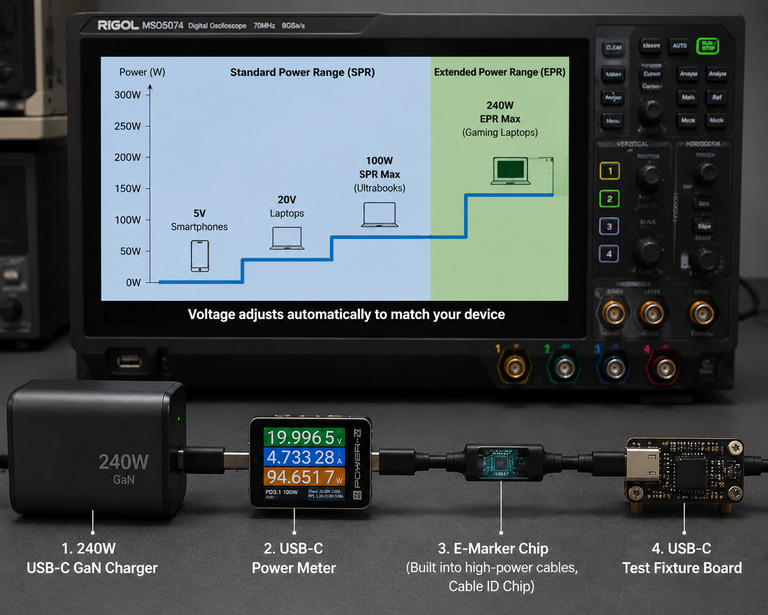
- SPR (Standard Power Range): The standard set of 5V / 9V / 15V / 20V voltage levels, with a maximum of 100W at 5A.
- EPR (Extended Power Range): Adds 28V / 36V / 48V voltage levels, with a maximum of 240W at 5A, for high-power devices. Full EPR performance requires a fully compliant EPR cable, charger and device.
- Analogy: Instead of the charger forcing a single fixed voltage onto every device, USB PD is like a smart delivery system. The device tells the charger exactly how much voltage and current it needs at any moment, and the charger adjusts accordingly. SPR covers phones, tablets and most laptops; EPR extends the system to power-hungry workstations, gaming laptops and large displays.
4.2 Power Roles & Direction
- USB-C supports three power roles: Source (power provider), Sink (power receiver), and DRP (Dual-Role Port) which can switch between the two.
- The power direction can be dynamically swapped, enabling features like reverse charging — for example, a laptop charging a phone, or a phone powering a USB drive.
- Analogy: Older USB ports only worked one way — power always flowed out of the charger and into the device, like a one-way street. USB-C is a two-way road. A DRP port can flip direction on command, so the same port can charge your laptop and also act as a power source for your headphones or USB drive.
4.3 Cables & E-Marker Chips
- Not every USB-C cable has an e-Marker chip. They are only required for high-power, high-speed, and EPR-rated cables.
- The e-Marker chip stores the cable’s capabilities: its rated current, maximum bandwidth, and supported protocol version.
- The charger and device read this information over the CC pin, and only enable power levels and speeds the cable can safely handle.
- Analogy: The e-Marker is the cable’s official ID card and safety certification. A basic cable has no ID, so the system only allows it to carry low power and low speed. A high-power, high-speed cable shows its ID to the control tower (CC pin), proving it can safely handle 100W+ power and 40Gbps+ speeds — and only then does the system unlock full performance.
5. Compatibility & Expansion
5.1 Adapters & Converters
- With adapters, USB-C can connect to legacy interfaces like HDMI, VGA, RJ45 Ethernet, and USB-A.
- Protocol conversion introduces a small amount of performance overhead. For high-speed, high-resolution or high-power use cases, the quality and capability of the adapter’s internal conversion chip matters greatly.
- Analogy: An adapter is like a port terminal with different loading docks. It takes the USB-C signal and repackages it to work with older cable types. Basic adapters work fine for everyday use, but for high-speed or high-resolution work you need a well-built adapter with a capable conversion chip.
5.2 Key Differences From Older USB Ports
- Compared to USB-A / USB-B, USB-C is smaller, reversible, supports far higher power limits, and integrates data, video and power all in one connector.
- High-power and high-speed features only work with properly rated cables. A basic USB-A to USB-C cable is limited in both power and functionality, and cannot support USB 3.x, PD high power, or Alt Mode.
- Analogy: Older USB-A is a single-purpose, one-way plug — like an old wall socket that only does one thing. USB-C is a universal smart port. But just because the plug fits does not mean you get all the features: you need the right grade of “pipe” (cable) to unlock the full speed and power.
5.3 Common Use Cases
- USB-C is now used across smartphones, laptops, tablets, monitors, docking stations, power banks, game consoles and more.
- It is steadily becoming the universal standard connector for both consumer electronics and industrial equipment.
- Analogy: USB-C is evolving into the universal “shipping standard” for the tech world. Instead of every device needing its own special plug and cable, almost everything can connect, charge and transfer data through one standard interface.
6. Key Takeaways
- USB-C’s 24-pin symmetric mirrored design is what enables its signature reversible plug-and-play usability.
- The port separates functions into dedicated pins: VBUS/GND for power, CC1/CC2 for control and PD communication, D+/D- for USB 2.0, and TX/RX high-speed pairs for fast data and video.
- High-speed modes like USB4 and Thunderbolt use all 4 differential pairs, while Alt Mode repurposes those pairs for native video output.
- USB PD runs over the CC pins, enabling dynamic voltage negotiation, bidirectional power flow, and up to 240W with the EPR specification.
- High power and high speeds require matching cables with e-Marker chips. A cheap basic cable will limit performance even on a high-end port.
- USB-C is much more than a charging port — it is a universal multi-function interface that is unifying power, data, video and expansion across nearly all modern electronics.