
Most people have used Qualcomm Quick Charge chargers and smartphones, but few know this: inside classic USB-A and Micro-USB ports, the two tiny D+ and D- pins — originally built only for file transfers — actually act as the hidden “command control room” for all fast charging.
Think of charging your phone like refueling a car at a full-service gas station. The thick VBUS power wires are the fuel hose that actually pumps gasoline into your tank. The thin D+ and D- pins are the dedicated intercom line between your car and the station control booth: your car tells the station exactly what fuel grade and flow rate it needs, the station adjusts its pumps accordingly, and the whole fast-charging process is coordinated entirely over these two tiny wires.
This guide uses simple, relatable analogies to break down QC’s design logic, version history, physical principles, and full handshake flow from start to finish. Even if you have zero hardware background, you will fully understand how it works.
1. Core Design Philosophy of the QC Protocol
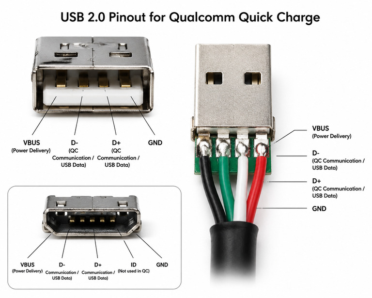
1.1 Why D+/D- Was Chosen for Fast Charging Communication
Before USB-C and CC pins existed, mainstream USB-A and Micro-USB connectors had no dedicated “fast charging communication pins.” Qualcomm’s choice to reuse D+/D- is essentially “adding a smart access system to an old house without rewiring.” It is the same idea as how old telephone lines were reused to carry ADSL internet: you do not need to dig up the street and lay new cables — you just run a new type of signal over the existing wires that sit idle most of the time.
- No dedicated pins on legacy interfaces: USB-A / Micro-USB lack the dedicated CC communication pins found on USB-C, so they cannot natively support USB PD fast charging. This is like an old apartment building with no dedicated intercom; you have to repurpose existing wiring for new functions.
- Pins are idle during pure charging: When only charging (no data transfer), the D+/D- data pins sit unused and can be safely repurposed. It is similar to a railway line that carries passenger trains during the day and freight trains at night: when no data is being transferred, the pins are free to take on a second job as charging control lines.
- Zero extra hardware cost: No new pins, no connector redesign — it works perfectly with all older USB ports and cables. New features are delivered over existing wiring with no retrofit cost.
- Built on a mature standard: QC fast charging is fully built on top of the USB BC1.2 charging specification. It is like paving a base highway first, then running fast cars on it — guaranteeing basic compatibility and safety.
1.2 Why Data Transfer Is Unavailable During High-Voltage QC Charging
Many people wonder: why can’t my phone transfer files while connected to a QC fast charger? The core reason is that one pair of wires cannot run two completely incompatible signal modes at the same time.
This is like trying to run both high-speed passenger trains and slow freight trains on a single track with two completely different signaling systems — they will collide:
- For USB 2.0 data transfer, D+/D- carry high-speed differential signals with rapid voltage transitions — like two people having a fast conversation, using quick level flips to send data.
- In QC high-voltage mode, D+/D- are repurposed to carry steady DC analog levels — like using light bulbs (on / dim / off) to send fixed commands, using stable voltage values to express requests.
The two signal modes are completely incompatible. Just as a single phone line cannot carry a voice call and a Morse code lamp signal at the same time, data communication must pause once high-voltage fast charging activates.
Note: In BC1.2 CDP mode (such as a labeled fast-charging USB port on a computer), 5V normal charging and data transfer can work simultaneously — like carrying simple information alongside a low-speed call, with no conflict.
1.3 Division of Roles: D+/D- vs. VBUS (Core Layering)
In the QC system, the two paths have strictly separate roles, just like a complete power grid. You can also think of it like an airport:
- D+/D- = communication control line: Only carries control commands such as “what voltage is needed” and transmits no electrical energy. They are the air traffic control radio frequencies — they only carry instructions and coordination; no planes ever fly through them.
- VBUS = power transmission line: The main path that actually delivers charging energy. It is the runway and taxiway system, where all the actual aircraft (electrical energy) travel.
After receiving commands via D+/D-, the charger adjusts its DC-DC circuit to change the VBUS output voltage. On the device side, the PMIC (Power Management Integrated Circuit) steps down the high voltage to match the battery and controls the final charging current — like a neighborhood transformer and pressure reducer, converting high-voltage grid power into safe household voltage.
1.4 BC1.2 Pre-Detection: The Real First Step of QC
QC fast charging does not start handshaking immediately upon plug-in. The very first step is BC1.2 port detection. Think of this as the ID check at the entrance of a venue: before the bouncer will even talk to you about VIP access (high-voltage charging), they first verify you meet the basic entry requirement. Only after you pass this initial check does the actual QC “VIP negotiation” begin.
The USB BC1.2 standard defines three types of USB ports:
- SDP (Standard Downstream Port): A regular computer USB port, up to 500mA current, supports data transfer, with pull-down resistors on D+ and D-.
- CDP (Charging Downstream Port): A labeled fast-charging computer USB port, up to 1.5A at 5V, supports charging and data transfer at the same time.
- DCP (Dedicated Charging Port): Wall chargers and car chargers fall into this category. They do not support data transfer but can supply high current. Physically, D+ and D- are shorted together inside the charger.
When plugged in, the device first checks whether D+ and D- are shorted. If it detects a short, it identifies the port as a DCP dedicated charging port capable of high-current charging, and only then initiates the QC high-voltage handshake. A DCP port that supports QC high voltage is professionally called an HVDCP (High-Voltage Dedicated Charging Port).
2. Quick Charge Protocol Evolution (Official Versions)
The evolution of QC is like the evolution of automotive powertrains — from single-speed bicycles, to manual transmissions, to CVTs, to all-new EV platforms. Each generation continuously improves efficiency, power, and flexibility.
QC 1.0
- Fixed 5V output, approximately 10W maximum (5V/2A)
- Essentially high-current charging based on USB DCP mode. It is like a standard garden hose with a fixed nozzle — only one water pressure setting. It delivers more water than a tiny trickle, but it is not what anyone would call “fast filling.”
QC 2.0
- First to introduce high-voltage fast charging, with two classes:
- Class A: 5V / 9V / 12V fixed voltage levels, for mobile devices like phones, up to 24W peak
- Class B: adds 20V level, for higher-power devices like tablets and laptops
- Think of it as a shower head with three fixed spray settings: low, medium, and high. You can jump between preset levels, but you cannot fine-tune to an exact pressure in between. This was the generation that made QC mainstream.
QC 3.0
- Added INOV (Intelligent Negotiation for Optimum Voltage) algorithm, supporting continuous voltage adjustment in 200mV steps
- Class A: 3.6V ~ 12V continuously adjustable; Class B: 3.6V ~ 20V continuously adjustable
- This is like a shower with a smooth, continuous pressure dial. You can twist it little by little to find the exact water pressure that feels perfect, instead of being locked into three rough presets. Efficiency improved by 38% and heat reduced by 45% compared to QC 2.0.
QC 3+
- A mid-range optimized version of QC 3.0. Focuses on improving light-load efficiency and thermal performance, while the core voltage regulation mechanism is identical to QC 3.0. It is the same smooth-dial shower, but with an improved valve that wastes less water and runs quieter at low flow rates.
QC 4
- Switched entirely to USB PD architecture. D+/D- are no longer the main communication channel; instead, the CC pins on USB-C are used.
- Supports USB PD PPS (Programmable Power Supply), with fine voltage steps of 20mV.
- This is like tearing out the old shower plumbing entirely and installing a whole-home smart water system with a dedicated digital control line. The old D+/D- “dials” are no longer the main control method. Backward compatibility with QC 2.0/3.0 depends on the device manufacturer’s implementation.
QC 4+
- Dual-protocol-stack design, supporting both USB PD and legacy QC 2.0/3.0 protocols.
- Like a “dual-fuel car” — works with the new PD standard and is also compatible with older QC devices, greatly improving compatibility.
QC 5
- Supports over 100W charging power (exact maximum depends on device design)
- Adds Battery Saver technology, Smart Identification, multi-path charging, and 12 layers of safety protection
- Like a high-performance EV platform: high power, fast charging, and a complete battery health management system.
QC 5+ (Qualcomm’s latest standard, September 2025)
- Built on USB PD-PPS at the underlying layer; D+/D- are only used for backward compatibility with older devices
- Maximum power 140W (20V / 7A)
- Adds intelligent dynamic thermal management for higher sustained charging efficiency
- Backward compatible with all QC generations, with lower accessory costs
- The latest generation high-performance power delivery platform: more power, smarter thermal control, and compatibility with all older chargers.
3. Core Principle of QC Speed Boost
The essence of fast charging is increasing charging power, and the power formula is very simple:
P (Power) = U (Voltage) × I (Current)
Just like the total water flow from a pipe = water pressure × flow speed: to get more water out, you can either raise the pressure or increase the flow.
You can also think of it like a highway. The number of cars on the road is the electrical current, and the speed limit is the voltage. To move more people per hour (more power), you can either cram more cars onto the road (higher current) or raise the speed limit (higher voltage).
QC chose the path of raising the transmission voltage, and the core reason is that cable loss is proportional to the square of the current (loss formula: P_loss = I² × R):
- If you cram more cars onto the road, traffic jams and friction skyrocket — cars slow down, waste fuel, and create heat. If you double the current, cable heat and loss become 4 times higher. A thin pipe cannot handle it; you must upgrade to a thicker cable.
- If you raise the speed limit instead, the same number of cars move much more people far more efficiently, with far less congestion and waste. If you double the voltage, the current can be halved for the same power, and cable loss drops to 1/4. Cable heat is greatly reduced, and regular charging cables can carry high power. This is just like high-voltage power lines: they can transmit large amounts of power over long distances without thick cables, and with very low loss.
Finally, after the high voltage reaches the device, the PMIC steps it down before charging the battery — just like high-pressure municipal water must pass through a pressure reducer to reach safe household pressure before reaching the tap.
4. Physical Layer Fundamentals: The “Light Signal Code” on D+/D-
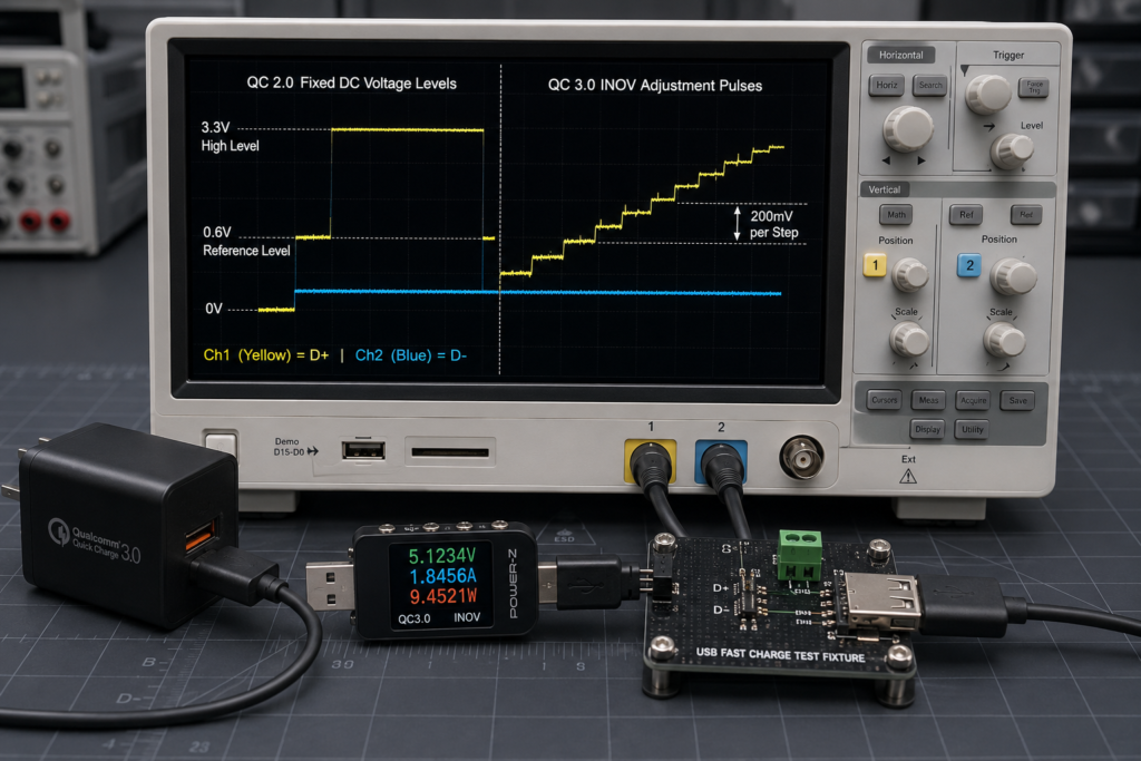
QC 2.0 and QC 3.0 rely entirely on different voltage levels on D+/D- to send commands. It is essentially a set of analog voltage “light signals”: both sides agree in advance what each brightness level means, the device sends commands by changing pin voltage, and the charger executes the corresponding operation after recognizing the voltage.
4.1 Standard Level Definitions
Both sides agree on several key voltage levels, just like pre-agreed brightness levels for a signal lamp:
- 0V: Logic low level, equivalent to “lamp fully off”
- 0.325V: Typical QC handshake detection threshold on the charger side, equivalent to “faint glow, used to confirm the other party is online”
- 0.6V: Basic handshake reference level, equivalent to “dim light, basic command level”
- 3.3V: High level for high-voltage gear determination, equivalent to “bright light, high-voltage command level”
- Hi-Z (High Impedance / Floating): Abnormal state, equivalent to “lamp broken / line disconnected”. The charger will forcibly fall back to the 5V safe state.
4.2 QC 2.0 Fixed Gear Level Mapping
QC 2.0 uses fixed voltage gears, selecting gears via the brightness combination of D+ and D-. It works just like an old rotary dial telephone: each unique combination “dials” one specific voltage setting, and the charger recognizes the combination and locks into that gear.
| D+ Level | D- Level | Requested Voltage | Analogy |
|---|---|---|---|
| 0.6V (dim) | 0V (off) | 5V | 1st floor, default safe gear |
| 3.3V (bright) | 0.6V (dim) | 9V | 3rd floor, common fast-charging gear |
| 0.6V (dim) | 0.6V (dim) | 12V | 5th floor, high-power gear |
| 3.3V (bright) | 3.3V (bright) | 20V | 10th floor, Class B devices only |
4.3 QC 3.0 INOV: Pulse-Controlled “Up/Down Buttons” for Stepless Regulation
Instead of fixed gears, QC 3.0 uses pulse signals for continuous voltage adjustment — just like elevator up/down buttons, where one press moves you up or down one floor (0.2V).
- Default hold state: D+ 0.6V / D- 3.3V, equivalent to standby; the elevator stays on the current floor.
- Up Pulse (+0.2V): Pull D+ from 0.6V up to 3.3V, hold for at least 2ms, then return to the hold state. A single pulse completes a 200mV voltage increase — press the up button once, go up one floor.
- Down Pulse (-0.2V): Pull D- from 3.3V down to 0.6V, hold for at least 2ms, then return to the hold state. A single pulse completes a 200mV voltage decrease — press the down button once, go down one floor.
During charging, the device continuously sends pulses based on the battery status, fine-tuning the voltage in real time to always keep charging efficiency in the optimal range.
4.4 Analog Level Anti-Interference Mechanism
Are analog signals prone to interference? QC is designed with a complete fault-tolerance mechanism. This works just like how your eyes recognize a traffic light: you do not need to measure the exact wavelength of red light to know it means “stop” — as long as the color falls within the general “red” range, you understand the signal.
- The charger uses a voltage comparator + ADC sampling to identify levels. It does not need millivolt-level precision; as long as the level falls within the valid range, recognition is successful.
- Built-in hysteresis comparison and recognition windows filter out misjudgments caused by high-frequency noise and ripple — just like your eyes ignore fleeting glares and flickers from sunlight and do not treat them as valid signals.
5. Full Protocol Handshake Sequence: 10 Steps From Plug-In to Fast Charge
The QC handshake is exactly like ordering food at a sit-down restaurant, step by step. If any step goes wrong, the system falls back to the safe 5V mode.
- Physical connection: You walk in and sit down at a table. The waiter brings you a glass of water (default 5V power) right away.
- BC1.2 DCP detection: The waiter confirms you are here to eat, not just to use the Wi-Fi. The device checks whether D+/D- are shorted to confirm it is a dedicated charging port.
- QC handshake trigger: You close your menu and make eye contact with the waiter to signal you are ready to order. The device outputs a detection level of approximately 0.325V on the D+ pin.
- Level hold: You keep your signal visible for a moment to make sure the waiter saw you. This level is maintained for approximately 1.25 seconds, waiting for the charger to respond.
- Charger response: The waiter nods and walks toward your table. After recognizing the QC request, the charger disconnects the internal D+/D- short.
- Device confirms readiness: You see the waiter approaching and know they are ready to take your order. The device detects a voltage drop on D- (≥1ms debounce) and confirms the charger supports QC.
- Voltage request: You tell the waiter exactly what meal you want. The device outputs the target D+/D- level combination and formally requests the corresponding voltage.
- Charger voltage regulation: The waiter sends your order to the kitchen, and the cooks start preparing your food. The charger’s DC-DC circuit operates and adjusts VBUS to the target voltage.
- Continuous dynamic adjustment (QC 3.0 and above only): Halfway through your meal, you ask for a little more salt or a glass refill — small, ongoing adjustments to make the experience perfect. The device continuously sends Up/Down pulses to fine-tune the voltage in real time.
- Abnormal exit: If you walk out early, or the kitchen loses power, everything stops and the table is reset to its default empty state. When level abnormality, communication timeout, physical disconnection, etc. occur, the system immediately exits QC mode and VBUS returns to default 5V.
6. Fundamental Differences Between QC and USB PD
Many people cannot tell QC and PD apart. They are essentially two completely different communication systems.
Another way to look at it: QC is like a coastal lighthouse using flashing light patterns to send simple messages to ships. It works over existing infrastructure, but it can only send very basic signals, it is easy to confuse in fog, and it only works one way. USB PD is like a modern satellite communications link: it uses a dedicated digital channel, can send complex data in both directions, has built-in error correction so messages never get garbled, and can handle far more advanced features.
| Dimension | QC (D+/D- Analog System) | USB PD (CC Digital System) |
|---|---|---|
| Communication Pins | D+ / D- | CC1 / CC2 |
| Signal Type | DC analog level | Digital BMC encoded signal |
| Verification Mechanism | No data verification, relies on level tolerance | CRC data verification, retransmittable on error |
| Power Direction | Unidirectional (charger → device) | Bidirectional DRP, supports reverse power supply |
| Physical Interface | Mainly for USB-A / Micro-USB | USB-C connector, supports up to 48V EPR expansion |
| Analogy | Lighthouse light signals: simple but limited, prone to interference | Satellite digital link: full features, high reliability, two-way communication |
7. Exception Protection and Degradation Mechanisms
The QC protocol is designed with a complete set of fault-tolerance and protection mechanisms. Any abnormality will prioritize returning to a safe state, just like the safety systems in a modern elevator:
- Abnormal D+/D- level sampling: Immediately fall back to 5V. Like when elevator doors do not fully close, the elevator refuses to move and stays on the current floor.
- Timeout with no valid level interaction: Automatically exit fast charging and maintain 5V output. Like when no button press is detected for a long time, the elevator returns to the lobby.
- Level deviation due to excessive cable impedance: Handshake fails, fall back to 5V. Like when a button signal is too weak to read, the elevator ignores it and stays in safe mode.
- Overcurrent / overtemperature protection: Gradually lower voltage gears and reduce output power. Like when the elevator motor overheats, it automatically slows down to reduce strain.
- Output short circuit: Immediately shut down output to prevent device damage. Like when the elevator cable snaps, emergency brakes lock immediately to stop the car.
- D+/D- floating / disconnection: Immediately exit fast charging and fall back to 5V. Like when the control panel loses power, the elevator immediately stops and locks in a safe state.
8. Engineering Implementation Notes
8.1 Multi-Protocol Coexistence and Identification
The D+/D- pins on a USB-A port are not only used by QC — fast charging protocols such as Huawei FCP, Samsung AFC, and Apple 2.4A all reuse these two pins.
This is like how multiple radio stations can broadcast on the same general frequency band, each using a different timing and pattern. A receiver can tell them apart by the rhythm and structure of the signal, even though they are all using the same airwaves. There is no digital “station ID number” — the system recognizes protocols entirely by their signal behavior and timing, using time-domain window isolation and feature detection.
8.2 Cable and Hardware Sensitivity
Compared with digital PD, QC analog levels are more sensitive to hardware. This is like trying to read a handwritten note through a long, foggy tunnel: the longer and dirtier the tunnel, the harder it is to make out the writing.
- Poor cable quality or excessive internal resistance will cause level deviation, causing the charger to fail to recognize the signal. Just like a wire that is too long and too thin makes a bulb dim enough that the other party cannot accurately recognize it.
- The accuracy of the sampling resistor directly affects recognition reliability. Analog signals are inherently less fault-tolerant than digital signals.
8.3 Chip Implementation Differences
Qualcomm’s complete QC protocol specification requires an NDA to obtain, and most public details come from the datasheets of various fast-charging chips. Controllers from different manufacturers have slight differences in level thresholds, pulse widths, and timeout durations — this is one reason why “charger and phone are incompatible” occasionally occurs, like two people speaking slightly different dialects of the same language.
9. Key Conclusions
- D+/D- are only responsible for communication negotiation; the actual charging energy is transmitted through the VBUS line, with a clear division of labor.
- QC 2.0 and QC 3.0 rely entirely on D+/D- analog levels to implement fast charging negotiation, making them typical analog fast charging protocols.
- Starting from QC 4, Qualcomm completely switched to the USB PD / PPS digital protocol architecture, and D+/D- are no longer the main communication channel.
- QC 5 and QC 5+ are based on the USB PD-PPS protocol at the underlying layer, and D+/D- are retained only for backward compatibility with older devices.
- QC 5+ is Qualcomm’s latest standard released in 2025, supporting up to 140W charging power, focusing on intelligent temperature control and efficient charging.
- With the popularization of USB-C connectors and the USB PD standard, analog fast charging negotiation based on D+/D- is gradually being replaced by digital communication based on CC pins — but it still has irreplaceable compatibility value in the massive installed base of USB-A and Micro-USB devices.
10. Common Misconceptions (FAQ)
Q1: Why can’t I transfer data while using QC high-voltage mode?
A: QC high-voltage mode repurposes D+/D- for DC analog levels, while USB 2.0 data transfer relies on high-speed differential switching signals on D+/D-. The two signal modes are completely incompatible and cannot work at the same time. It is like you cannot make a phone call on the same line while using it to send Morse code light signals — one will completely overwrite the other.
Q2: Why does QC choose to raise voltage instead of increasing current?
A: Cable loss is proportional to the square of the current. Raising voltage and reducing current can greatly reduce cable heat and energy loss, allowing regular charging cables to carry high power without custom thick wires. It is just like high-voltage power lines: they can transmit large amounts of power without thick cables, and with lower loss. Trying to push more current through a thin wire is like trying to push a flood through a garden hose — it creates massive friction, heat, and waste.
Q3: Why don’t USB-C ports use D+/D- as the main fast charging channel?
A: USB-C connectors are natively equipped with CC communication pins, which support digital communication, bidirectional power supply, and finer voltage regulation. Their reliability and functional scalability are far superior to analog solutions. It is like having dedicated fiber-optic broadband — there is no need to dial up over a phone line anymore.
Q4: Why is USB PD considered more advanced than QC?
A: USB PD is a universal digital charging standard that supports bidirectional power supply, multi-device negotiation, CRC data verification, higher power limits, and a more open and unified protocol ecosystem. Early QC was a proprietary analog protocol led by Qualcomm, which is weaker than PD in terms of functionality and versatility. It is the difference between a single-purpose walkie-talkie and a full-featured smartphone.
Q5: Why do modern USB-C phones still support the QC protocol?
A: Mainly for backward compatibility with older USB-A chargers and cables, so that users can still achieve fast charging with old chargers. At present, mainstream fast charging technology has fully shifted to the USB PD/PPS digital system, and QC mostly exists as a compatibility option — like a new car that still has a radio to play old FM stations.