
Quick Summary
- Core Definition: Modern multi-port USB-C chargers rely on a coordinated chipset — including power management ICs (PMICs), USB PD controllers, DC-DC converters and GaN power stages — that act as the intelligent power dispatch system. Together they allocate wattage across ports, negotiate fast-charging protocols, and enforce full-circuit safety protections.
- Key Value: Dynamic Power Sharing (DPS) built on this chipset architecture lets one charger efficiently power multiple devices at once, unlocking high wattage in compact GaN form factors.
- Buying Rule of Thumb: Prioritize total power output, protocol compatibility, dynamic allocation capability, and safety certifications over raw port count.
1. Basics: Understanding Multi-Port Charger Power Management
1.1 What Is a Power Management IC (PMIC)?
A Power Management Integrated Circuit (PMIC) manages and regulates electrical power by controlling voltage conversion, power paths, system monitoring and protection functions through integrated power-management circuits.
Rather than performing raw power conversion itself, a PMIC orchestrates how power is distributed, stabilized and protected across a system — making it a foundational building block for everything from smartphones to charging stations.
1.2 The Multi-Port Charger System: It’s Not Just One Chip
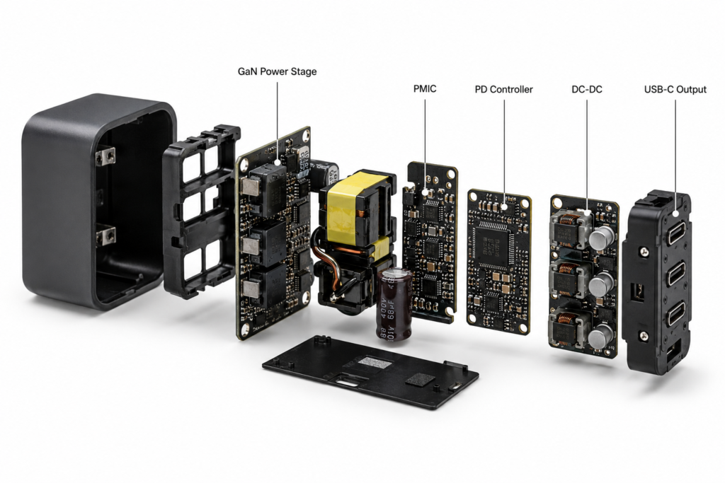
A multi-port charger is rarely built around a single “all-in-one” chip. Real-world designs use a layered chipset architecture split between the primary (AC-to-DC) side and secondary (port control) side.
In low-wattage compact chargers, some secondary-side functions may be merged into highly integrated ICs; in 140W–240W high-power designs, they are almost always separate chips working in sync.
1.3 Key Chip Types in a Multi-Port Charger
| Chip Type | Core Function | Role in Multi-Port Chargers |
|---|---|---|
| PMIC | Manages power rails, power path logic and system-level protection | Handles distribution, load balancing and safety coordination across ports |
| USB PD Controller | Manages USB-C CC pin communication and protocol negotiation | Talks to connected devices to agree on voltage/current profiles |
| DC-DC Converter | Converts one DC voltage level to another (Buck / Buck-Boost) | Regulates output for each port to match requested charging levels |
| Power Switch / Load Switch | Controls power on/off and prevents reverse current | Enables per-port power path control and fault isolation |
| MCU | System intelligence, firmware control and host communication | Enables smart scheduling, OTA updates and advanced feature sets in premium chargers |
1.4 Clarification: What a PMIC Does (and Doesn’t Do)
A PMIC is one of the key control elements on the secondary side, working in tandem with PD controllers, DC-DC regulators and dedicated protection ICs. It is not the entire charging system, nor does it typically handle primary-side AC-DC conversion or GaN switching directly.
1.5 Brief Evolution: From Single-Port to Smart Multi-Port Charging
- Early single-port era: Fixed 5V output with basic overcurrent protection — no smart scheduling needed.
- Multi-port early days: Simple physical current splitting, no protocol handshake, low power efficiency.
- Modern smart era: USB PD standards and GaN technology turned multi-port chargers into compact, high-wattage intelligent systems with coordinated chipset architectures.
2. Why Smart Power Management Has Become Essential
2.1 The Multi-Device Charging Problem
The average user owns 3–4 rechargeable electronics: a phone, tablet, laptop, wireless earbuds, or smartwatch. Charging them all at once used to mean a pile of adapters and a crowded power strip — a problem intelligent multi-port power systems were built to solve.
2.2 USB PD: The Standard That Made Smart Multi-Port Charging Possible
USB Power Delivery evolved quickly to enable higher power and finer control:
- PD 3.0 + PPS: Up to 100W with programmable power supply via APDO
- Voltage range: 3.3V–21V
- Voltage step: 20mV
- Current step: 50mA
- PD 3.1 EPR: Extended power range up to 240W
- SPR (Standard Power Range): 5V–20V, up to 100W
- EPR (Extended Power Range): 15V–48V, up to 240W
- AVS (Adjustable Voltage Supply): 100mV adjustment step
Note: Full 240W EPR performance requires an EPR-rated charger, EPR-certified cable and EPR-compatible device — all three must match.
Higher total power and finer voltage control made smart power distribution no longer optional.
2.3 GaN Technology: Shrinking Size, Boosting Power Density
Gallium Nitride (GaN) power switches run at higher frequencies with far less energy loss than legacy silicon designs. That shrinks transformers and heatsinks dramatically, making 100W+ multi-port chargers small enough for travel — and advanced PMIC + PD controller chipsets are the control brain that makes this compact GaN charger architecture work reliably.
2.4 Global Efficiency Regulations: DoE Level VI & CoC Tier 2
Regulations like US DoE Level VI and EU CoC Tier 2 set strict limits on standby power waste:
- DoE Level VI: ≤100mW no-load power for adapters under 49W; ≤210mW for 49–250W
- CoC Tier 2: ≤75mW no-load for under 49W; ≤150mW for 49–250W
Modern fast charging PMIC designs include low-standby modes and light-load efficiency tuning to meet these mandatory standards.
2.5 The Shift From “Charges Devices” to “Charges Smartly”
People no longer settle for chargers that slow down every time you plug in a second device. They expect smooth, intelligent charging — and that’s exactly what a well-designed PMIC + PD controller chipset delivers.
3. How It Works: Inside a Multi-Port GaN Charger
3.1 Full System Architecture Breakdown
Complete charging system flow:
Wall AC input → Rectifier → PFC Controller (if required) → Primary Flyback / LLC Controller → GaN MOSFET Power Stage → Transformer → Synchronous Rectification → DC Bus → Secondary Power Management (PMIC + per-port PD controllers + DC-DC regulators) → USB output ports → Your devices
Primary-Side Topologies
| Topology | Typical Use Case |
|---|---|
| Flyback | Most mainstream wall chargers (30W–100W) |
| LLC Resonant | High-power chargers (100W–240W+) for higher efficiency |
Secondary-Side Topologies
| Topology | Typical Use Case |
|---|---|
| Buck (step-down) | Standard fixed-input wall charger output regulation |
| Buck-Boost | Car chargers, power banks and variable-input systems |
| Independent per-channel | High-end desktop charging stations |
3.2 Core Functional Blocks of the Power Management System
A modern multi-port charging system packs several specialized blocks across its chipset:
- Power distribution control unit: The central “calculator” that divides total power across ports
- Power path management: Routes power cleanly between ports and prevents reverse current
- USB PD protocol interface: Handles CC-pin communication and PDO/APDO/EPR negotiation
- Sensing unit: Constantly reads voltage, current, and system temperature
- Protection execution unit: Triggers safety measures when anomalies are detected
3.3 Power Allocation Strategies: Fixed vs. Dynamic Power Sharing
Fixed Power Allocation
Each port gets a pre-set maximum wattage (e.g., 65W for C1, 18W for A1).
- Pros: Simple design, lower cost
- Cons: Wastes power — if one port is idle, its capacity cannot be used by others
Dynamic Power Sharing (DPS) & Power Pool Architecture
The system operates on a shared total power pool architecture. The chipset monitors every port in real time and reassigns wattage from the pool as devices connect and disconnect.
- Illustrative example for a 100W charger:
- 1 device: Full 100W to the active port
- 2 devices: 65W + 35W automatically
- 3 devices: 45W + 30W + 18W balanced distribution
Actual power allocation depends on charger firmware, thermal limits, and individual device negotiation results — there is no universal split standard for 100W chargers.
- Two switching styles:
- Hard reset negotiation: Briefly drops power then re-handshakes (common in budget models)
- Smooth power transition: Adjusts voltage gradually without interruption (premium designs)
Priority-Based Scheduling
Many systems prioritize high-power devices (like laptops) first, then assign remaining watts to phones and accessories — so your notebook does not slow down just because you plugged in earbuds.
3.4 USB PD Negotiation: How PDOs, APDOs and EPR AVS Work
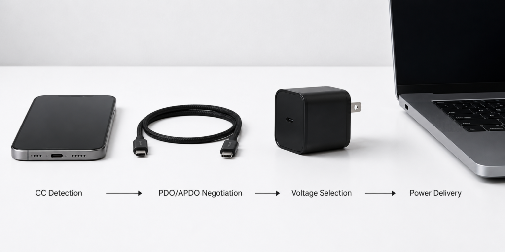
Think of this as the chipset being a multilingual translator. The full negotiation flow:
- CC pin detects a device is connected
- PD controller reads the device’s advertised PDOs (Power Delivery Objects)
- For PPS-capable devices, APDOs (Augmented PDOs) enable fine 20mV step voltage tuning
- For EPR-capable systems, AVS profiles support 100mV steps up to 48V
- Controller selects the optimal supported profile
- PMIC adjusts the DC-DC converter to match the requested voltage/current
- Charging begins and is continuously monitored
Top USB PD controller chips support USB PD 3.1 EPR, PPS, QC 5, and major brand protocols — all automatically.
3.5 Layered Safety Protection System
Multi-port power systems include layered safety that works together:
- OVP (Over-Voltage Protection): Stops output if voltage spikes
- OCP (Over-Current Protection): Cuts power if current exceeds limits
- OTP (Over-Temperature Protection): Throttles power if the system gets too hot
- SCP (Short-Circuit Protection): Instantly shuts down on a short
- UVP (Under-Voltage Protection): Prevents unstable low-voltage output
Thermal derating is especially important: instead of shutting off completely, the system gently reduces power to stay within safe temperature limits.
4. Key Specs You Need to Understand
4.1 Power-Related Specs
- Total output power: The maximum watts the system can deliver overall. Common tiers:
- 35W: Phones + small accessories
- 65W: Thin-and-light laptops + phone
- 100W: Laptop + multiple devices
- 140W–240W: High-performance laptops and workstations
- Single-port peak power & blind-charge support: Whether every USB-C port can deliver full power when used alone. “Blind plug” means you never have to remember which port is the “fast one.”
- Allocation accuracy & response speed: How precisely power is split, and how fast it rebalances when you add or remove a device.
4.2 Efficiency & Energy Specs
| Technology | Typical System Efficiency |
|---|---|
| Silicon MOSFET charger | 88–92% |
| GaN-based charger | 92–95% |
- No-load standby power: How much power the charger wastes when plugged in but not charging. Quality designs hit 30–75mW, easily meeting global standards.
- Switching frequency: Higher frequency means smaller components — but also more EMI (electromagnetic interference) challenges.
- Thermal performance: Measured by thermal resistance (θJA) and maximum junction temperature (Tj max).
4.3 Protocol & Compatibility Specs
- Supported protocol range: Universal standards (USB PD, PPS, QC) plus brand-specific protocols
- Negotiation speed & reliability: How fast and consistently the chipset locks into the correct charging mode
4.4 Safety & Reliability Specs
- Protection threshold accuracy
- ESD rating (HBM/CDM) for electrostatic durability
- MTBF (Mean Time Between Failures) for long-term reliability
5. Design Architectures & Integration Levels
5.1 By Power Architecture
| Architecture | Typical Use Case | Key Traits |
|---|---|---|
| Single shared DC bus | Most consumer GaN chargers | All ports draw from one common DC rail; low cost, simple design |
| Independent power modules | Premium desktop chargers | Each port has its own regulation stage; highest stability and flexibility |
| Multi-phase power stage | 200W+ high-power systems | Parallel power stages share load; better thermal performance |
5.2 By System Integration Level
Highly Integrated Single-Chip Solutions
Multiple secondary-side functions — DC-DC regulation, basic PD control, protection — merged into one IC.
- Pros: Small PCB size, simple design, lower BOM cost
- Best for: Low-to-mid power consumer multi-port chargers, entry-level desktop stations
Discrete Chipset Design
Separate chips for primary control, DC-DC regulation, and per-port PD handling.
- Pros: Maximum flexibility, higher power capability, easier to optimize per channel
- Best for: High-power premium chargers, professional-grade products
Digital Power + MCU Smart Control
Programmable DC-DC and protocol chips managed by a microcontroller over I2C/SPI.
- Pros: Most flexible, supports OTA firmware updates for new protocols
- Best for: High-end desktop chargers, outdoor power stations, industrial systems
5.3 By Port Configuration
- 2-port: 2C or 1C1A (most travel-friendly)
- 3-port: 2C1A or 3C (the most popular everyday format)
- 4+ ports: Desktop charging stations for home or office
6. Major Manufacturers & Representative ICs
6.1 Global Industry Leaders
- Texas Instruments (TI): A benchmark for reliability. The TPS25750 and TPS25751 are widely adopted USB-C PD controllers, with the TPS25751 adding PD 3.1 EPR support. They are paired with dedicated PMICs and DC-DC converters to form complete multi-port charging systems.
- Infineon: A leader in both GaN power devices and PD controllers. Its EZ-PD CCGx family (including CYPD3177, CYPD4236) is widely used in advanced USB-C applications including docking stations, monitors and high-performance chargers.
- MPS (Monolithic Power Systems): Specializes in high-density power management ICs used in a wide range of power management and charging applications, often deployed alongside dedicated USB PD controller chips.
- onsemi, Renesas, Richtek: Strong offerings in primary-side controllers, power regulation ICs and multi-rail management for consumer and industrial use.
6.2 Chinese High-Value Manufacturers
| Vendor | Representative ICs | Market Position |
|---|---|---|
| Southchip | SC8721, SC8701 | Leading domestic multi-port charging PMIC vendor |
| Injoinic | IP5389, IP2736 | Popular for power bank and multi-port charger SoCs |
| iSmartWare | SW3516, SW3518 | Widely used in consumer multi-port GaN chargers |
| Hynetek | HUSB series | USB PD controller solutions |
| JoulWatt | JW series | High-efficiency DC-DC and power management |
6.3 GaN Co-Packaged Solutions
The latest trend combines GaN power FETs, gate drivers, and control logic into a single package — shrinking size further and improving reliability. Infineon, Navitas, and Innoscience are pushing this integrated approach forward.
7. Real-World Applications
7.1 Consumer Electronics
- Multi-port GaN wall chargers & desktop stations: Replace 3–4 adapters with one compact device
- USB-C docks & monitors: Deliver power, data, and video over a single cable
- Multi-port power banks: Bidirectional charging with smart output management
7.2 Automotive & Outdoor
- Car multi-port chargers: Work with 12V/24V vehicle systems to fast-charge laptops and phones
- Outdoor power stations: Multi-output bidirectional management, often with solar input support
7.3 Industrial & IoT
- Embedded industrial controllers and self-service terminals
- Unified power for multi-sensor IoT nodes
Real-world reference: Teardowns of premium chargers from top brands consistently use well-matched PMIC + PD controller chipsets from leading vendors — chip selection is a strong indicator of build quality in multi-port GaN charger design.
8. Buying & Selection Guide
8.1 For Everyday Users: 5-Step Charger Buying Method
- Add up your power needs: Total the peak watts of devices you charge simultaneously (phone: 25–65W, tablet: 30–45W, laptop: 65–100W, gaming laptop: 140W+).
- Match your devices’ protocols: Apple devices work best with USB PD/PPS; Android flagships may need brand-specific protocol support.
- Prefer dynamic power sharing: It makes far better use of total power than fixed allocation.
- Check safety and thermal build: Look for UL, CE, FCC, or other regional safety marks. For high-wattage models, GaN charger architecture runs cooler.
- Pick port count for your use case: 2 ports for travel, 3 ports for daily use, 4+ for a fixed desktop setup.
8.2 For Semi-Pro Users: Chipset Selection Tips
- Define product type and total power budget first
- Match port count and allocation strategy to your use case
- Verify protocol support and licensing requirements
- Factor in thermal design, EMI, and safety certification needs
- Balance BOM cost against performance and reliability targets
9. Common Myths & Troubleshooting
9.1 Three Persistent Myths Debunked
- ❌ Myth: More ports = more total power ✅ Fact: Total power is set by the overall design. A cheap 4-port charger may deliver less total wattage than a well-built 2-port model.
- ❌ Myth: More supported protocols = faster charging ✅ Fact: What matters is whether it supports your device’s protocol — and has proper brand licensing. Listing 10 protocols doesn’t help if none run at full speed.
- ❌ Myth: Dynamic sharing lets every port run at full speed at once ✅ Fact: Total power is a fixed pool. Dynamic sharing just uses it more efficiently — it doesn’t create extra watts.
9.2 Common Issues Explained
- Charging slows down with a second device: Normal behavior — total power is being split.
- Devices briefly disconnect when you plug in a new one: The charger is re-negotiating power distribution. Premium models do this seamlessly; budget ones may drop out for a split second.
- Charger feels warm during use: Mild warmth is normal. If it’s uncomfortably hot or throttles power heavily, check ambient temperature and whether you’re exceeding the rated load.
- Fast charge won’t trigger: Check your cable (E-Marker cables are required for >60W PD), confirm protocol support, and make sure another device isn’t using most of the power.
- Laptop won’t charge at full speed: Verify total charger wattage, PD version compatibility, and that no other port is drawing high power.
10. Frequently Asked Questions (FAQ)
Q1: What’s the real difference between a PMIC and a USB PD controller?
A PMIC handles power distribution, voltage regulation and system protection. A USB PD controller handles the communication protocol with connected devices. In multi-port chargers they work together — the PD controller “talks” to devices, and the PMIC delivers the requested power.
Q2: Does charging multiple devices at once damage batteries?
No. Reputable charging systems follow standard protocols and include full safety protections. Each device still receives exactly the voltage and current it requests. Poor-quality uncertified chargers are the risk, not multi-port design itself.
Q3: Does ambient temperature affect output power?
Yes. All chips have thermal limits. In very hot environments, the PMIC will reduce output to stay within safe temperatures — this is by design, not a defect.
Q4: Why do cheap multi-port chargers feel slower?
Many budget models use fixed power allocation, older topologies, and lower-efficiency designs. They also often skip premium features like smooth power transition and full protocol licensing.
Q5: Is a 3-port design much harder to build than 2-port?
Yes. Adding a third port increases complexity in power distribution logic, thermal management, and protocol handling — which is why well-executed 3-port chargers cost more than simple 2-port models.
Q6: What separates entry-level from high-end multi-port power systems?
Three main gaps: allocation accuracy and smoothness, protocol support depth and licensing, and efficiency/thermal performance across the full load range.
Q7: Why does a 140W (or 240W) charger not always output its full rated wattage?
Full rated power is only available under ideal conditions. Real-world output is limited by four factors: total system power cap, thermal derating in warm environments, cable rating (EPR cables are required for >100W), and the actual power requested by the connected device.
11. Future Trends
11.1 Higher Power Standards
USB PD 3.1 EPR (up to 240W) is moving from niche to mainstream, and future revisions may push limits even higher.
11.2 Deeper Integration
GaN FETs, drivers, and power management logic will increasingly merge into single-package solutions — smaller, more reliable, and easier to design with.
11.3 AI-Assisted Power Management
Next-generation digital PMICs will use adaptive algorithms to:
- Predict user charging patterns
- Optimize thermal distribution across ports
- Dynamically adjust charging priority based on usage context
11.4 Protocol Convergence
Unified fast-charging standards will gradually reduce protocol fragmentation, making broad compatibility easier to achieve.
11.5 Expanding Use Cases
Wired + wireless unified charging, multi-port energy routers, and solar-direct systems will push USB-C charger IC technology far beyond phone chargers.
12. Final Thoughts
The modern multi-port charging system is the unsung hero of the multi-device era. What looks like a simple “charger with more ports” actually relies on sophisticated real-time power scheduling, multilingual protocol negotiation, and layered safety protection — coordinated across PMICs, PD controllers and GaN power stages.
Whether you’re shopping for a daily charger or designing a power product, remember: the quality of the internal chipset matters more than the number of ports on the outside. A well-designed GaN charger architecture delivers faster, cooler, more reliable charging — and makes the “one charger for everything” vision actually work.
13. References & Sources
- USB-IF official USB Power Delivery specification documents
- Official datasheets from Texas Instruments, Infineon, MPS and other chip vendors
- US DoE Level VI & EU CoC Tier 2 external power supply efficiency standards
- Industry analyst reports from Yole Group, TrendForce on GaN and power IC markets
- Independent teardown and testing data from ChargerLAB and technical review sources