
Quick Summary
The flyback converter is the most widely used topology for low-power isolated switch-mode power supplies (SMPS), and the core circuit inside nearly all phone chargers, USB PD fast chargers, and small appliance power adapters. Its core operating principle is “store energy first, then release it”, converting high-voltage AC to low-voltage DC through high-frequency switching and a transformer.
Key advantages of the flyback topology include its simple structure, low cost, built-in electrical isolation, and support for wide global input voltages, making it ideal for mass-market consumer electronics. Its main limitation is a typical power ceiling of around 150W; at higher power levels, it is less efficient than more complex topologies like LLC resonant converters.
1. Introduction: Why Flyback Converters Are in Every Charger
1.1 From Everyday Charging to Power Conversion
Every phone charger, laptop power brick, and USB-C fast charger you own is essentially an energy converter: it takes the 100–240V high-voltage alternating current (AC) from a wall socket and turns it into the low-voltage direct current (DC) — 5V, 9V, 20V and more — that your devices can use.
This is far more than just “stepping down voltage”. It requires balancing safety, size, efficiency, and cost. The specific circuit design used — called a power topology — defines a charger’s core performance.
1.2 How Power Topology Shapes Your Charger Experience
Think of a power topology as the blueprint for a charger. The design chosen directly determines:
- Conversion efficiency: how much heat is generated and how much energy is wasted
- Size and weight: whether the charger fits in your pocket
- Safety: whether there is risk of electric shock
- Production cost: the final retail price For low-power applications up to tens of watts, the flyback converter offers the best overall balance of all these factors.
1.3 The Industry Role of Flyback Converters
The flyback converter is a classic, entry-level topology for isolated SMPS with decades of history and extremely mature technology. It is used across consumer electronics, home appliances, lighting, and industrial auxiliary power — and it is the dominant architecture in the smartphone chargers we use every day.
2. Basics of the Flyback Converter
2.1 What Is a Flyback Converter?
A flyback converter is an isolated SMPS circuit with a transformer. Its defining feature is that energy transfer happens in two steps: energy is stored in the transformer when the switch is on, and released to the load when the switch is off.
As a simple analogy: an ordinary transformer is like a straight pipe — water flows in one end and out the other immediately. A flyback converter is more like a water tank system: water is first stored in the tank, then released to the user on demand.
2.2 Where the Name “Flyback” Comes From
The name comes from its unique behavior: when the control switch turns off, the voltage polarity on the transformer’s secondary winding reverses (flies back), turning on the output circuit and delivering energy to the load.
This is the opposite of a forward converter, which transfers energy directly while the switch is on, with no polarity reversal.
2.3 Flyback Transformers ≠ Ordinary Line-Frequency Transformers
Many people confuse the flyback transformer with the heavy iron transformers in old chargers, but they work very differently:
- Ordinary line-frequency transformers only change voltage level and transfer energy in real time. When the primary is energized, current flows immediately on the secondary side.
- Flyback transformers are essentially coupled inductors. They both transform voltage and store energy. The secondary side outputs nothing when the primary is on — energy only releases when the switch turns off. To store more energy, flyback transformers use a gapped magnetic core and operate at frequencies from tens to hundreds of kilohertz, which is why they can be so small.
3. Core Structure and Key Components
A typical flyback charger has four main functional blocks: input stage, switching control stage, transformer core, and output stage.
3.1 Input Rectification and Filtering
This is the first stop for incoming power, consisting of a rectifier bridge, input filter capacitor, and EMI filter components.
- Rectifier bridge: converts bidirectional AC into pulsating DC that flows in only one direction
- Input capacitor: smooths out the pulsating DC into a steadier voltage
- EMI filter: reduces electromagnetic interference generated by the circuit, so it does not disrupt other devices
3.2 Power Switch and Control IC
The core components here are the MOSFET power switch and the PWM controller chip.
- The MOSFET acts as an ultra-high-speed electronic switch, turning on and off tens or hundreds of thousands of times per second to control the flow of energy
- The PWM controller is the “brain”: it monitors the output voltage and automatically adjusts how long the switch stays on to keep the output stable
3.3 The Flyback Transformer
This is the heart of the circuit, serving three critical functions:
- Electrical isolation: physically separates the high-voltage input from the low-voltage output, preventing mains voltage from reaching your phone
- Voltage conversion: steps high voltage down to the required level via the turns ratio between primary and secondary windings
- Energy storage: holds energy in the magnetic field when the switch is on, and releases it when the switch is off
3.4 Output Rectification and Feedback
The output side consists of rectifiers, filter capacitors, and a feedback loop.
- Rectifier (diode or synchronous rectifier): allows current to flow in only one direction, turning pulsed energy into steady DC
- Output filter capacitor: smooths the output voltage and powers the load during the switch-off period
- Feedback loop (usually an optocoupler): sends output voltage information back to the controller for automatic voltage regulation
4. Step-by-Step Working Principle
The flyback converter follows a very predictable cycle: store energy, then release energy, repeated at high frequency.
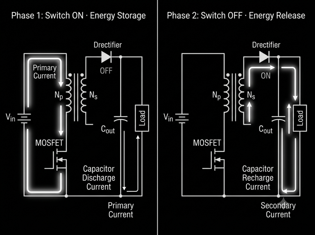
4.1 Phase 1: Switch On — Energy Storage
When the MOSFET switch closes and connects high-voltage DC to the primary winding:
- Primary current ramps up, the magnetic field in the core strengthens, and energy is stored in the magnetic field
- At this point, the induced voltage on the secondary winding is reversed, so the output rectifier is off and no current flows on the secondary side
- The load — your phone, for example — is powered entirely by the output filter capacitor
4.2 Phase 2: Switch Off — Energy Release
When the MOSFET switch opens and cuts off the primary current, the magnetic field in the core starts to collapse:
- By electromagnetic induction, the secondary winding develops a reversed voltage that turns on the rectifier
- Energy stored in the core is released through the secondary winding: some powers the load directly, and some recharges the output capacitor
- Once the energy is released, the switch turns on again and the cycle repeats
4.3 High-Frequency Cycling and Voltage Regulation
This on-off cycle repeats tens to hundreds of thousands of times per second — this is the switching frequency. Because it happens so fast, the output capacitor barely discharges before being recharged, so the device receives nearly steady DC power.
Voltage is regulated by adjusting the fraction of time the switch stays on, called the duty cycle: if output voltage drops, the switch stays on longer to transfer more energy; if voltage rises, the on-time is shortened to reduce energy transfer.
5. Three Operating Modes and Use Cases
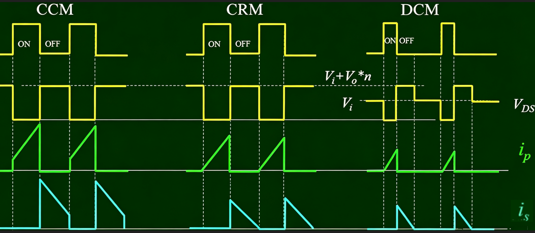
Flyback converters are classified into three operating modes based on whether the inductor current drops to zero each cycle, each suited to different power levels and performance goals.
| Operating Mode | Core Characteristic | Advantages | Disadvantages | Typical Use Case |
|---|---|---|---|---|
| Discontinuous Conduction Mode (DCM) | Inductor current drops fully to zero each cycle; all energy is released | Simple control logic, low cost | Higher peak current, higher ripple | Low-power phone chargers under 30W |
| Continuous Conduction Mode (CCM) | Inductor current never reaches zero; energy is not fully released | Lower output ripple, higher efficiency | More complex control, higher cost | Medium-power adapters 60–150W |
| Critical Conduction Mode (CRM) | Operates right at the boundary where current reaches zero | Balances efficiency and control complexity | Variable frequency, slightly more complex EMI design | Some mid-range and high-end fast chargers |
As a general rule: lower-power designs favor DCM for low cost, while higher-power designs favor CCM for efficiency and stability.
6. Key Technical Features
6.1 Built-In Electrical Isolation
Flyback converters use a transformer to physically separate input and output — there is no direct electrical connection between them. This means even if a fault occurs on the high-voltage side, it cannot reach low-voltage devices like phones and laptops.
This design meets international safety standards such as IEC 60950 and is the reason nearly all wall-plug chargers use an isolated topology.
6.2 Wide Global Input Voltage Range
Flyback topologies can adapt to large input voltage swings by adjusting the duty cycle. Most chargers labeled “100–240V~” work with mains voltages anywhere in the world. You only need a plug adapter when traveling internationally — no extra voltage transformer is required.
6.3 Power Range Limits
Flyback converters are most commonly used from a few watts up to about 150W. Beyond that, transformer size, heat, and switch stress rise quickly, and the cost-effectiveness drops off.
For higher-power supplies — like desktop PC power supplies or high-power server power — topologies like forward, half-bridge, and LLC resonant converters are preferred.
6.4 Leakage Inductance and Spike Suppression
No flyback transformer achieves perfect magnetic coupling. A small portion of the magnetic energy does not transfer to the secondary — this is called leakage inductance. When the switch turns off, leakage inductance creates high voltage spikes that can damage the switch.
Traditional designs use an RCD snubber circuit to dissipate this energy, which costs a small amount of efficiency. Higher-end designs use active clamp technology to recover and reuse leakage energy, reducing spikes while improving efficiency.
7. Advantages and Limitations
7.1 Core Advantages
- Simple circuit structure: fewer components, mature design, and high manufacturing yield
- Low production cost: excellent for mass production of consumer electronics
- Natural electrical isolation: easily meets safety requirements without extra isolation hardware
- Easy multi-output design: multiple voltage outputs are possible simply by adding secondary windings
- Wide voltage compatibility: works with mains voltages worldwide
7.2 Inherent Limitations
- Limited power capacity: not suitable for applications above 150W
- Higher output ripple: voltage fluctuation is higher than topologies like LLC, requiring more filtering
- Leakage inductance losses: leakage energy is either wasted or requires extra circuitry to recover
- High switch voltage stress: the switch experiences high voltage during turn-off, requiring more robust components
8. Comparison With Other Common Power Topologies
To better understand where flyback fits in, here is how it compares to other common power supply topologies.
| Comparison | Flyback Converter | Buck Converter | Forward Converter | LLC Resonant Converter |
|---|---|---|---|---|
| Electrical Isolation | Yes | No | Yes | Yes |
| Power Range | Few W ~ 150W | Few W ~ tens of W | 100W ~ 500W | 100W ~ several kW |
| Circuit Complexity | Low | Very low | Medium | High |
| Conversion Efficiency | Moderate | Relatively high | Moderately high | High |
| Component Cost | Low | Very low | Medium | High |
| Typical Use | Phone chargers, low-power adapters | On-board DC step-down | Desktop PC auxiliary power, mid-power adapters | High-power fast chargers, TV power, server power supplies |
In short: use Buck for non-isolated step-down, flyback for low-power isolated designs, forward for medium-power isolated designs, and LLC for high-power high-efficiency designs.
9. Typical Applications in Chargers
9.1 Standard and Low-Power Fast Phone Chargers
Virtually all 5W to 25W original phone chargers use flyback topology. At these power levels, its cost and size advantages are unmatched, and its maturity makes it the clear default choice.
9.2 USB-C PD Fast Charging Adapters
The 30W to 65W USB-C PD charger market still relies heavily on flyback architecture. Paired with upgrades like gallium nitride (GaN) switches and synchronous rectification, even conventional flyback can achieve high efficiency in a very small form factor.
9.3 Laptop Power Adapters
Many 45W to 65W ultrabook adapters still use flyback topology. Higher-power gaming laptop adapters — 90W, 130W and above — increasingly move to more efficient topologies like LLC resonant converters.
9.4 Other Everyday Uses
Beyond chargers, flyback converters are all around us: standby power for TVs and air conditioners, LED lighting drivers, and power adapters for routers and set-top boxes are almost always flyback circuits.
10. Modern Upgrades to Flyback Charger Technology
Traditional flyback has modest performance limits, but new materials and architectures continue to improve it — most visibly in today’s GaN fast chargers.
10.1 Gallium Nitride (GaN) Switches
GaN is a third-generation semiconductor material. GaN switches turn on and off much faster than traditional silicon MOSFETs, with far lower switching losses. This allows flyback circuits to run at higher frequencies, shrinking the transformer further while running cooler and more efficiently.
The palm-sized 65W fast chargers available today are built around a GaN + flyback architecture.
10.2 Synchronous Rectification
Traditional flyback designs use a diode on the output for rectification, but diodes have a forward voltage drop that wastes power. Synchronous rectification replaces the diode with a very low-resistance MOSFET, drastically reducing output-side losses, boosting overall efficiency, and reducing heat.
Nearly all mid-range and high-end fast chargers today include synchronous rectification.
10.3 Active Clamp Flyback (ACF)
Active clamp flyback is an advanced version of the conventional flyback. It adds an extra switch and capacitor to form a clamp circuit that recovers leakage energy instead of wasting it.
Compared with standard flyback, ACF delivers higher efficiency, lower switch stress, and less heat. It is the preferred architecture for premium GaN chargers.
10.4 Digital Control ICs
Traditional flyback uses analog control chips with fixed functionality. Digital control chips enable more precise voltage regulation and faster dynamic response, plus native support for fast charging protocols like USB PD and PPS. A single chip handles both control and protocol negotiation, simplifying the overall design.
11. Common Misconceptions and FAQs
11.1 Common Misconceptions
- Myth: Flyback transformers work the same way as old-fashioned iron transformers They are fundamentally different. Old line-frequency transformers transfer energy in real time and step voltage down via turns ratio. Flyback transformers operate on a store-and-release principle, are essentially coupled inductors, run at hundreds of times higher frequency, and are much smaller.
- Myth: Flyback can only step voltage down, not up Flyback is essentially an isolated Buck-Boost architecture. It can both step down and step up voltage by adjusting the winding turns ratio. Some high-voltage driver circuits use flyback specifically to generate higher voltages.
- Myth: Higher power chargers use more advanced technology Power rating is just a specification, not a measure of technological advancement. Low-power flyback is actually more mature and cost-effective than many higher-power topologies. What matters most is matching the charger to your device, along with efficiency and build quality.
11.2 Frequently Asked Questions
Q: Why do almost all phone chargers use flyback topology?
A: Phone chargers are low-power, cost-sensitive, require small size, and must include safety isolation. Flyback topology matches all these requirements perfectly — it is the optimal choice when balancing cost, size, safety, and reliability.
Q: Is there a shock risk with flyback chargers?
A: A properly certified flyback charger has full electrical isolation and poses no shock risk under normal use. The transformer’s insulation barrier completely separates high-voltage mains from the low-voltage output, in compliance with international safety standards.
Q: Are GaN chargers still flyback-based?
A: Most low- and medium-power GaN chargers still use a flyback architecture — often the advanced active clamp flyback (ACF) variant. GaN is an upgrade to the switch material; it does not change the underlying working principle of the topology.
Q: Is heat from fast chargers caused by flyback topology?
A: It contributes, but it is not the only factor. All power conversion produces losses and heat. Flyback is indeed less efficient than LLC, but reputable products operate within safe temperature limits. Heat depends more on power density, thermal design, and load level.
Q: Do I need to care about flyback topology when buying a charger?
A: For everyday consumers, not at all. Any reputable, safety-certified charger will work fine regardless of topology. Focus on power rating, charging protocol compatibility, physical size, and price instead.
12. Summary and Future Trends
12.1 Key Takeaways
The flyback converter is a timeless classic in low-power isolated power supplies. Its two-step store-and-release principle enables safe, efficient isolated power conversion.
Thanks to its simple structure, low cost, natural isolation, and wide voltage compatibility, flyback topology dominates the consumer electronics market for phone chargers and low-power adapters. It is one of the most common power technologies in daily life — even if most people never notice it.
12.2 Future Directions
- Material advances: Third-generation semiconductors like GaN and SiC will further boost efficiency and switching frequency, enabling even smaller designs
- Architecture evolution: Active clamp flyback (ACF) will gradually replace conventional flyback as the standard for mid-range and high-end fast chargers
- Integration: Highly integrated control chips will simplify designs and lower manufacturing barriers
- Power boundary shift: High-power fast charging above 100W will increasingly move to LLC and other high-efficiency topologies, while flyback continues to dominate the low- and medium-power space