
Introduction
If you have ever picked up a fast charger mid-charge and noticed it warming up, you have witnessed the physical reality of power conversion. In an era where 65W, 100W, and even 240W USB-C Power Delivery (PD) chargers fit in the palm of your hand, heat management has become one of the most important measures of charger quality. An overheating charger does not just feel unpleasant — it can degrade internal components faster, reduce device battery life, and in extreme cases, create safety hazards.
Temperature rise stress testing is the industry’s core tool for measuring how a charger handles heat under real and extreme conditions. It does not just check if a charger gets warm; it verifies that the device stays within safe boundaries even when pushed to its design limits. This guide covers the fundamentals of charger heat generation, global safety standards, professional lab testing procedures, thermal performance differences across charger types, and how everyday users can interpret test results and use chargers safely.
1. Core Concepts: What Is Charger Temperature Rise Stress Testing?
Before diving into test procedures and standards, it is essential to clarify the basic terms that define thermal performance. Many users confuse “temperature” with “temperature rise,” and misunderstanding this difference can lead to incorrect judgments about charger safety.
1.1 Key Terms Explained
First, temperature rise is not the same as absolute temperature. Absolute temperature refers to how hot a surface feels in degrees Celsius. Temperature rise, by contrast, is the difference between the charger’s surface or component temperature and the surrounding air temperature, calculated as:
Temperature Rise (ΔT) = Measured Temperature – Ambient Temperature
This distinction matters because a charger tested in a 35°C room will naturally run hotter than one tested in a 20°C room, even with identical thermal design. Temperature rise removes the ambient variable, making it a fair, standardized measure of thermal performance.
Three temperature categories are used in all professional testing:
- Ambient temperature: The temperature of the surrounding air, measured away from the charger itself.
- Case / surface temperature: The temperature of the outer enclosure, which directly affects user touch safety.
- Internal component temperature: The temperature of chips, transformers, capacitors and other parts. These are almost always higher than surface temperatures, and they determine the charger’s actual lifespan.
1.2 The Purpose of Temperature Rise Stress Testing
A standard performance test checks whether a charger delivers its advertised wattage, negotiates USB-C PD protocols correctly, and maintains stable voltage. Temperature rise stress testing answers a more fundamental question: can this charger handle its rated power safely, over time, under pressure?
It validates three core dimensions:
- Thermal stability: Whether temperature levels off at a safe steady state instead of climbing continuously.
- Protection reliability: Whether overheat and overcurrent protection features activate correctly under extreme conditions.
- Long-term durability: Whether component temperatures stay within ratings that support a reasonable product lifespan.
In short, stress testing simulates worst-case scenarios to find a charger’s safety boundary — not just how it performs on a mild day, but how it holds up under sustained full load, high room temperatures, and even fault conditions.
1.3 Stress Testing vs. Everyday Warmth
It is normal for a charger to feel warm during use. In everyday charging, the load changes constantly: a phone pulls full power at the start, then gradually reduces current as the battery fills. The charger works in bursts, not at maximum output nonstop.
Stress testing is far more demanding. It runs the charger at 100% rated output continuously, often in elevated ambient temperatures, and sometimes with simulated fault conditions like blocked vents or short circuits. Where everyday use tests a charger in its comfort zone, stress testing pushes it to the edge of its design envelope to verify that even at the limit, it does not become unsafe.
2. Why Temperature Rise Testing Matters More Than Ever
A decade ago, most phone chargers delivered 5W to 10W and ran barely warm. Today’s USB-C PD chargers deliver 10 to 40 times more power in similarly sized bodies, making thermal performance a make-or-break feature.
2.1 High-Power Fast Charging Raises the Thermal Stakes
Charging power has climbed from 20W entry-level fast chargers to 240W high-performance PD adapters, while physical sizes have shrunk dramatically. Higher power density means more heat generated per cubic centimeter inside the case.
The mainstream adoption of USB-C Power Delivery has amplified this challenge. PD chargers operate at higher voltage and current combinations than older 5V chargers, and they must maintain stable, efficient power conversion across a wide range of output profiles. A poorly thermally designed PD charger may deliver its advertised wattage for five minutes, then overheat, throttle power, or trigger protection shutoffs when used continuously with a laptop.
When power density rises faster than thermal design improves, heat becomes the invisible bottleneck that limits real-world performance. A charger’s peak wattage number looks impressive on the box, but it means very little if the unit cannot sustain that power without overheating.
2.2 Multi-Device Charging Creates Sustained Thermal Load
Multi-port chargers have become standard for users who carry a phone, tablet, laptop, and wireless earbuds. When all ports are in use simultaneously, the charger runs near its total power limit for extended periods.
This continuous full-load operation causes heat to build up inside the enclosure. In single-port phone charging, the load drops as the battery fills, giving the charger time to cool. In a multi-port desktop setup, the charger may run at high output for hours on end. Good temperature rise testing replicates this exact scenario, verifying that the charger does not overheat under sustained multi-device load.
2.3 Global Climate and Grid Differences Add Complexity
A charger sold worldwide must work reliably across regions with very different ambient temperatures and grid voltages. Mains voltage varies from 100V in Japan to 120V in North America to 230V–240V across most of Europe, Asia, and Oceania. Conversion efficiency and heat generation shift slightly at different input voltages.
In hot climates, higher ambient temperatures directly raise the charger’s baseline temperature, making thermal design margins much tighter. A charger that runs cool in a 22°C Scandinavian home may approach its temperature limits when used in a 38°C summer room in the Middle East or Southeast Asia.
2.4 The Real Risks of Excessive Heat
The consequences of poor thermal design go beyond discomfort.
- Short-term issues: Overheating chargers often throttle their output, slowing charging speeds without warning. Some repeatedly cycle on and off as thermal protection triggers and resets.
- Long-term damage: High temperatures accelerate the aging of electrolytic capacitors, semiconductor chips, insulation materials, and solder joints. The widely cited rule of thumb is that component life roughly halves for every 10°C increase in operating temperature.
- Extreme safety hazards: In worst-case scenarios, sustained overheating can melt plastic enclosures, break down electrical insulation, cause internal short circuits, and create fire risk. Severe overheating can also create burn hazards on touchable surfaces.
Temperature rise testing exists precisely to prevent these outcomes by catching design flaws before products reach consumers.
3. Why Do Chargers Get Hot? The Science Behind the Heat
Every charger produces heat. It is not a sign of bad quality by itself — it is a basic consequence of converting alternating current (AC) from the wall into the direct current (DC) that devices use. Understanding where that heat comes from helps explain why some chargers run much hotter than others.
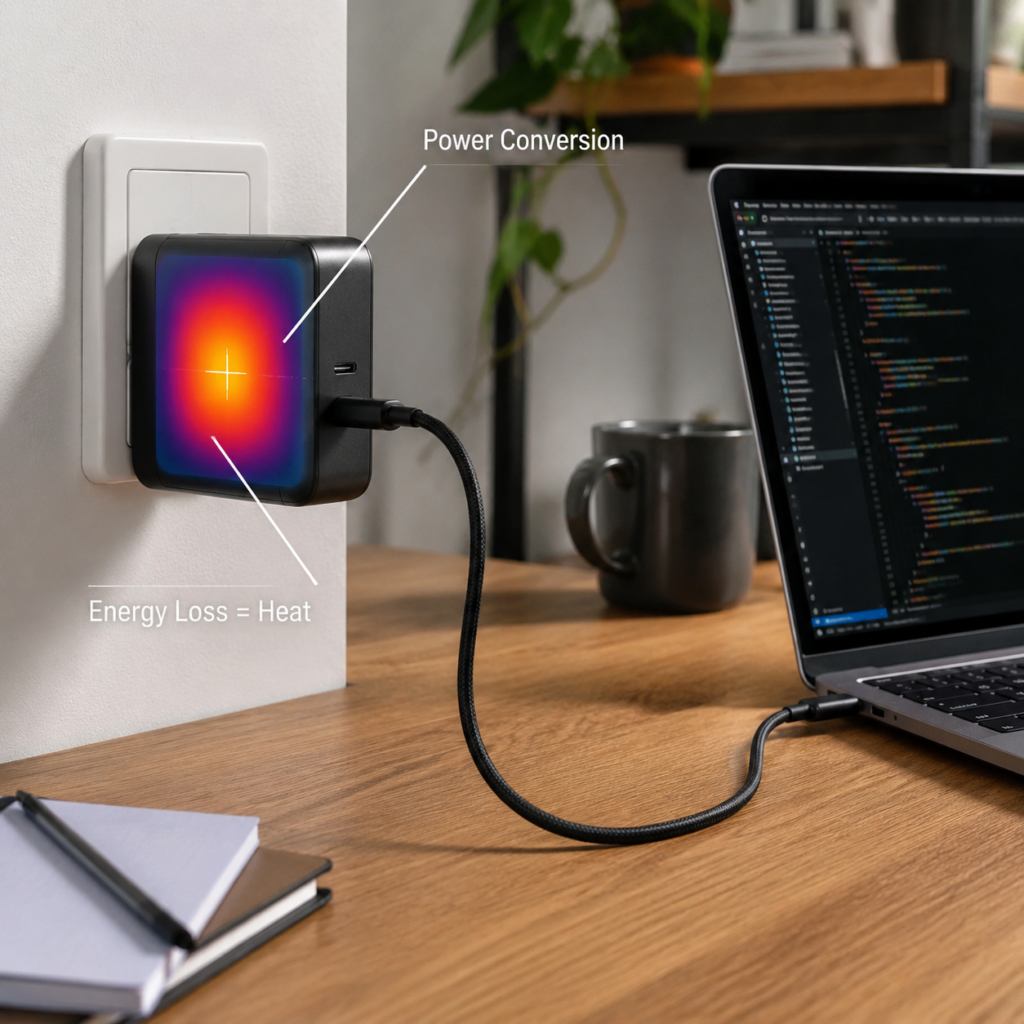
3.1 The Root Cause: Energy Conversion Losses
No power converter is 100% efficient. A small portion of incoming electricity is not delivered to your device; it is lost inside the charger, and almost all of that lost energy becomes heat.
Four sources account for nearly all internal heat generation:
- Power switch losses: The main semiconductor chips generate heat both when current flows through them and when they switch on and off at high frequency.
- Transformer losses: The transformer steps voltage down and provides electrical isolation. Its magnetic core and copper windings both produce heat.
- Rectifier and filtering losses: Output rectifiers and filtering capacitors contribute additional heat.
- Conductive losses: PCB traces, internal wiring, and connector pins have small resistance. At high currents, even small resistance generates noticeable heat.
3.2 Internal Design Factors That Shape Thermal Performance
How hot a charger ultimately runs depends heavily on engineering choices made at the design stage.
Semiconductor technology is the most visible factor. Traditional silicon MOSFETs have higher losses. Gallium nitride (GaN) semiconductors have much lower on-resistance and switching losses, allowing efficiency levels of 93%–95% compared to roughly 85% for older silicon designs at equivalent power levels.
Circuit topology also matters. More advanced architectures like active-clamp flyback and LLC resonant designs achieve higher efficiency than simpler flyback topologies, especially at higher power levels.
Thermal design determines how effectively generated heat escapes the enclosure, including thermal adhesives, heat spreaders, graphite sheets, and carefully designed casings.
PCB layout and manufacturing quality play a critical underappreciated role. Thicker copper on the circuit board reduces resistive losses in high-current paths. Smart component placement prevents hot spots from stacking. Poor soldering, loose crimps, or thin copper can create extra contact resistance, which becomes a local heat source that raises temperatures far beyond design intent.
3.3 External Factors That Affect Real-World Temperature
Even the best-designed charger will run hotter under some conditions than others.
- Ambient temperature: A charger in a 35°C room starts 10°C warmer than one in a 25°C room, so its peak temperature will be roughly 10°C higher, all else equal.
- Airflow and placement: A charger in open air can dissipate heat through natural convection. One tucked into a couch cushion or enclosed cabinet cannot cool itself properly and will run significantly hotter.
- Load level: A charger trickle-charging a nearly full phone produces very little heat. One running at full 65W output to charge a laptop generates maximum heat.
- Input voltage: Efficiency curves vary across input voltage ranges. A charger optimized for 230V may run slightly hotter at 100V input, or vice versa.
3.4 How Conversion Efficiency Directly Shapes Temperature Rise
Efficiency is the single most important number for predicting thermal performance. If a 65W charger is 94% efficient, it wastes 6% of input power as heat — about 4.1 watts of heat at full load. A less efficient 88% charger wastes 12% of input power, producing about 8.9 watts of heat — more than twice as much.
This is why two chargers with the same advertised wattage can feel very different in temperature. The difference is measurable physics: higher efficiency means less waste heat, lower component temperatures, longer life, and cooler outer surfaces.
Top-tier GaN chargers achieve their best efficiency at medium-to-high loads, which is exactly where users notice heat the most. Cheaper chargers may cut corners on semiconductor quality or transformer design to save cost, resulting in higher losses, more heat, and shorter service life — even if the printed wattage on the box looks identical.
4. Global Safety Standards: How Warm Is Too Warm?
Temperature rise is not judged by feel. It is governed by formal safety standards that define acceptable limits for touchable surfaces and internal components. These standards are built on decades of safety engineering and risk assessment.
4.1 International Baseline Standards
IEC 62368-1 is the leading modern safety standard for audio, video, information, and communication technology equipment, including chargers and power adapters. Unlike older standards that prescribed rigid temperature numbers, IEC 62368-1 uses a risk-based approach: it classifies energy sources, defines required safeguards, and sets requirements for touchable surface temperatures, material temperature ratings, and thermal protection measures.
The standard recognizes that different materials and different types of user contact carry different levels of risk. Metal surfaces conduct heat faster than plastic, so their allowable touch temperatures are lower. Parts that users hold continuously have stricter limits than surfaces they might only brush against accidentally.
IEC 60950-1 was the previous main standard for information technology equipment. It is still referenced in some regions, but it is being phased out and replaced by IEC 62368-1 worldwide.
4.2 Regional Certification and Compliance Requirements
Different countries and regions reference these international standards with local variations and certification frameworks.
- United States: UL 62368-1 is the primary safety standard for chargers sold in the US market. It sets strict requirements for accessible surface temperatures and internal component thermal limits, and UL certification requires rigorous third-party laboratory testing.
- European Union: Products placed on the EU market must meet applicable EN safety standards and undergo CE conformity assessment, of which thermal safety is an essential part. CE marking is a manufacturer’s declaration of compliance with all relevant EU directives, not a single test certification.
- Japan: The PSE regulatory framework includes temperature rise and safety performance evaluation for applicable electrical products. Requirements vary based on product classification.
- Australia and New Zealand: The AS/NZS 62368.1 standard applies, and SAA certification covers thermal testing requirements for chargers.
- United Kingdom: UKCA marking follows corresponding safety standards that include temperature rise evaluation clauses.
4.3 Understanding Temperature Rise Limits
There is no single universal temperature limit for all chargers. The allowable temperature rise depends on the applicable standard, product category, enclosure material, and how the user interacts with that surface.
For external touchable surfaces, plastic and metal enclosures have different temperature limits because they transfer heat to skin at different rates. Surfaces that users grip continuously have stricter limits than surfaces that are only occasionally touched.
For internal components, transformer windings have temperature limits based on their insulation class, with progressively higher allowable temperatures for Class A through Class H materials. Common consumer-grade electrolytic capacitors typically have core temperature ratings around 105°C. Semiconductor junction temperatures must stay below the device’s maximum rated value, usually with a safety margin applied.
The most important takeaway for everyday users is this: compliant chargers may feel warm, even noticeably warm, but their temperatures are held within engineering limits that support safe operation and reasonable product life.
4.4 What Certification Actually Means
A certification mark on a charger does not mean it will never get warm. No charger can break the laws of physics. What certification guarantees is that the product has been tested against recognized safety standards, its temperature rise falls within allowed limits under defined test conditions, and it includes appropriate protection mechanisms to prevent unsafe failure.
Certification sets the safety baseline. Within that baseline, there is still wide variation in thermal performance — some certified chargers run cool, others run closer to the limit. Certification tells you a product is safe; it does not tell you it has best-in-class thermal design.
5. Inside the Lab: How Professional Temperature Rise Testing Works
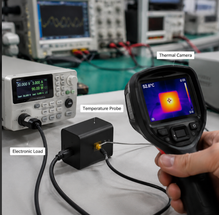
A proper charger temperature rise test is not just plugging in a charger and pointing an infrared thermometer at it. It follows standardized conditions, calibrated equipment, and defined procedures to produce repeatable, comparable results.
5.1 Pre-Test Setup and Standardized Conditions
Reliable results start with a controlled environment.
- Test environment: Tests are typically conducted in a temperature-controlled room set to approximately 25°C, with controlled humidity and no forced air flow. Direct sunlight or nearby heat sources are excluded.
- Test equipment: Key tools include multi-channel thermocouple data loggers for precise point measurements, programmable AC power sources that simulate different global grid voltages, programmable DC electronic loads that mimic devices, and thermal imaging cameras that visualize full-surface heat distribution.
- Sample preparation: Test units are placed in the test environment long enough to reach ambient temperature before testing begins. They are positioned according to real-world use, standing upright on a wooden surface as they would sit on a desk.
Thermocouples are attached to critical points both inside and outside the unit, using thermally conductive adhesive to ensure accurate readings.
5.2 Baseline Test: Full-Load Steady-State Temperature Rise
The core of any thermal test is the steady-state full-load test.
- Engineers set the charger to its rated input voltage and maximum rated output power. To reflect global use, tests are commonly repeated at multiple input voltages, such as 100V AC and 230V AC.
- The charger runs continuously until it reaches thermal equilibrium — the point at which temperature stops climbing and remains stable over time. Steady state is typically defined as a temperature change of 1°C or less over a set measurement interval.
- Throughout the test, data loggers record temperatures at regular intervals, building a temperature-vs-time curve for each measurement point.
This test reveals the charger’s normal operating temperature at full load. It is the baseline power adapter temperature test data that manufacturers use to verify compliance and compare designs.
5.3 Advanced Stress Testing: Pushing the Limits
Steady-state full load shows normal operation. Stress testing explores what happens when conditions get worse.
- Overload and abnormal load testing: Depending on applicable product standards, testers apply output conditions beyond the charger’s rated capacity to verify that protection circuits activate correctly and that temperatures do not reach unsafe levels before protection triggers.
- Elevated ambient temperature testing: The charger is placed in an environmental chamber at 40°C–45°C and run at full load. This simulates use in hot climates and verifies that the charger can maintain safe operation at the upper end of its rated ambient range.
- Abnormal condition testing: Testers simulate fault scenarios such as output short circuits and blocked ventilation openings. These tests verify that the charger fails safely — shutting down or limiting power — without catching fire, melting through the enclosure, or creating electric shock hazards. This category of testing directly addresses the root causes of USB-C charger overheating in real-world failure cases.
- Extended burn-in testing: The charger runs at full load for several hours to check for temperature drift, component aging effects, and long-term thermal stability.
5.4 Pass / Fail Decision Logic
A charger passes temperature rise testing when two conditions are met:
- Temperature at every measured point stays within the limits defined by the applicable safety standard.
- Under abnormal and overload conditions, all protection functions operate correctly, and no unsafe conditions — fire, melted enclosure, electric shock hazard — occur.
If any point exceeds its limit, or if the unit fails dangerously during fault testing, the design must be revised and retested.
5.5 How to Read a Temperature Rise Test Report
When you see third-party charger thermal test results online, you can evaluate them effectively by looking for five key pieces of information.
- Temperature rise curve: This graph plots temperature over time from a cold start. A good curve rises quickly at first, then flattens into a smooth plateau. If the line keeps climbing without leveling off, the charger may have a thermal runaway risk.
- Maximum temperature point: This is the highest temperature recorded anywhere on the charger, inside or out. It is the primary number used for pass/fail compliance judgments.
- Thermal stabilization time: This is how long the charger takes to reach steady temperature. Faster stabilization usually indicates better heat transfer out of the enclosure.
- Hot spot distribution: Thermal images show where heat concentrates on the surface. A well-designed charger spreads heat relatively evenly. A single intense hot spot can indicate poor internal layout. This is one of the most useful ways to assess fast charger thermal performance from test data.
- Abnormal temperature behavior: Watch for sudden jumps in temperature, temperature that never stabilizes, or temperatures that spike far higher under only slightly increased load. These are warning signs of marginal design.
6. Thermal Performance Differences Across Charger Types
Not all chargers handle heat the same way. Technology, form factor, power level, and intended use all create very different thermal profiles.
6.1 Silicon vs. GaN Chargers
Traditional silicon-based chargers use mature, low-cost semiconductor technology. They tend to be physically larger for a given wattage, and their efficiency is generally lower, meaning they produce more waste heat per watt of output. Their larger size, however, gives more surface area for cooling.
GaN (gallium nitride) chargers use wide-bandgap semiconductors that switch much faster and lose far less energy during switching. On paper, GaN produces less total heat per watt. In practice, GaN chargers are almost always built much smaller than equivalent silicon chargers, which compresses the heat into a smaller volume and raises power density dramatically.
The result is a common misconception: GaN chargers are not always cooler to the touch than silicon chargers. A well-designed GaN charger runs cooler internally and lasts longer, but its smaller case can actually feel warmer on the outside because the same amount of heat is escaping through less surface area. A poorly implemented budget GaN charger can run hotter than a decent silicon charger because the design cuts corners on thermal path construction.
6.2 Single-Port vs. Multi-Port Chargers
Single-port chargers have one main power conversion stage and one heat source. Their thermal design is relatively straightforward.
Multi-port chargers split power across multiple outputs. When all ports are active, total internal heat generation increases. Heat from different parts of the circuit can add up inside the enclosure. High-quality multi-port chargers use smart power allocation and thermal derating — they automatically reduce output power slightly if internal temperatures climb too high — to stay within safe limits while still delivering the most power possible.
6.3 Wired vs. Wireless Chargers
Wired chargers generate heat almost entirely from their internal power electronics. The charger itself is the primary heat source.
Wireless chargers add a second heat source: the inductive charging coil. Power transfer through magnetic induction has its own efficiency losses, so both the charger pad and the phone back get warm. Wireless chargers also require additional safety testing for foreign object detection (FOD) — if a metal object sits between the charger and the phone, it can heat up rapidly, creating a burn and fire risk.
6.4 Thermal Challenges by Power Class
- 20W–30W phone chargers: At this power level, thermal design is relatively easy. The biggest design priorities are small size, low standby power draw, and good light-load efficiency.
- 65W GaN chargers: This is the most competitive segment. The combination of high power and pocket-sized form factor makes thermal design the central engineering challenge. Long-term full-load stability is a key differentiator between budget and premium models.
- 100W–240W PD chargers: These high-power units charge laptops and multiple devices simultaneously. Robust full-load thermal management and multi-port heat control are non-negotiable. Cheap 240W chargers often cannot sustain their advertised power for more than a few minutes before thermal throttling kicks in.
6.5 Travel Chargers
Travel chargers occupy a special category built for worldwide use and maximum portability. They must handle every mains voltage from 100V to 240V reliably, and they are often left plugged in for hours or days at a time in hotel rooms. Their small size and wide input range make thermal design especially challenging. A good travel charger maintains consistent thermal performance across all input voltages, not just at the voltage it was primarily designed for.
7. Judging Thermal Quality: What Good and Bad Look Like
You do not need a lab to form a reasonable opinion about a charger’s thermal design. There are clear patterns that separate well-engineered units from problematic ones.
7.1 Three Levels of Thermal Behavior
- Normal operation: When operating within safety standards, a charger will typically feel noticeably warm under full load. This is expected and not a cause for concern — as long as the temperature stabilizes and does not keep climbing higher and higher.
- Warning signs: If the charger becomes uncomfortably hot to hold for more than a few seconds, if charging speed drops sharply partway through, or if you notice a faint chemical or plastic odor, the charger may be running near or beyond its design limits.
- Danger signs: If the charger is too hot to touch at all, if the plastic casing warps or discolors, if you smell burning, or if the charger repeatedly cuts out and restarts, stop using it immediately. These are classic indicators of serious thermal or electrical faults.
7.2 Characteristics of a Thermally Well-Designed Charger
High-quality chargers share recognizable thermal traits.
- Temperature rises smoothly and then levels off cleanly at a stable value. There are no sudden, unexplained jumps upward.
- Hot spots are within expected design locations. There are no unexpectedly intense, concentrated hot spots that suggest poor internal layout or unexpected heat sources.
- Under overload or high-temperature conditions, the charger’s built-in protection engages predictably. It may reduce output power or shut down temporarily, but it does not fail dangerously.
- Independent third-party lab temperature test data shows consistent, repeatable results. Thermal images show even heat distribution, and full-load temperature curves flatten reliably without runaway behavior.
7.3 Common Causes of Excessive Temperature Rise
When a charger runs hotter than it should, the cause usually falls into one of four categories.
- Overstated power and undersized components: The charger is advertised at a higher wattage than its internal parts can safely sustain. Components are chosen for cost, not for continuous full-load operation.
- Inadequate thermal design: The designer skimped on thermal adhesive, heat-spreading materials, or cooling path design. Heat gets trapped inside instead of dissipating through the case.
- Poor build quality: Bad solder joints, loose terminal connections, thin PCB copper, or cheap connectors create extra contact resistance, which becomes a local heat source.
- Protocol compatibility issues: A faulty or non-standard USB-C PD negotiation can cause the charger to operate outside its intended power range, leading to unexpected overheating.
8. Practical User Guide: Choose and Use Chargers Wisely
You do not need to be an engineer to select a thermally sound charger and use it safely. A few simple guidelines go a long way.
8.1 How to Estimate Thermal Performance Before Buying
- Check for recognized safety certifications: Look for UL, CE, PSE, SAA, or other applicable marks. Note that certification confirms baseline safety compliance; it does not by itself guarantee best-in-class thermal performance.
- Look for efficiency specifications: When manufacturers publish efficiency numbers, higher efficiency usually correlates with lower heat generation.
- Review independent test data: Reputable tech reviewers and testing sites publish full-load temperature measurements and thermal images. Look for charger temperature test data that clearly states test conditions — ambient temperature, input voltage, load level, and test duration.
8.2 Quick On-Hand Temperature Assessment
If you already own the charger, you can do a simple sanity check.
- Run the charger at full load — for example, charging a low-battery laptop — for about 30 minutes.
- Touch the surface with the back of your hand. If you cannot keep your hand in contact for more than a second or two, the surface temperature is likely quite high and warrants closer attention.
- Watch for warning signs: unusual odors, unusual buzzing or clicking sounds, bulging plastic, or frequent charging interruptions.
8.3 Simple Ways to Reduce Charger Temperature in Daily Use
Small changes in how you use your charger make a measurable difference.
- Place it in open air: Set the charger on a hard, open desk surface where air can circulate around it. Never tuck it under pillows, blankets, couch cushions, or inside closed drawers while in use.
- Keep it away from heat sources: Do not leave chargers on sun-heated car dashboards, near heaters, or on top of other warm electronics.
- Use appropriately sized loads and quality cables: Avoid forcing a charger to power devices beyond its intended rating. Use USB-C cables rated for the current you need — an underrated cable adds resistance and heat at the connections.
- Keep contacts clean: Dust and oxidation on plug pins and connector contacts increase resistance and heat. Wipe them occasionally with a clean, dry cloth.
8.4 Selecting Chargers With Appropriate Thermal Performance for Different Scenarios
- Everyday phone charging: Look for a reputable brand charger with appropriate safety certification. At 20W–30W, thermal performance is rarely a major issue with name-brand products.
- Laptop power and all-day use: Prioritize chargers with proven long-duration full-load thermal stability. A 65W–140W PD charger that sustains full power consistently is better than one that runs cool for ten minutes then throttles.
- Multi-device desktop setups: Choose multi-port chargers with documented intelligent power allocation and thermal derating behavior. These models manage heat proactively instead of abruptly shutting down.
- Use in hot climate regions: Select chargers with a wide operating temperature range and certifications relevant to your local market. In consistently warm environments, every degree of design margin matters.
9. Frequently Asked Questions
1. Is it bad if my charger gets warm while charging?
No. Mild to moderate warmth during charging is a normal result of energy conversion loss. What matters is whether the temperature stabilizes at a safe level and stays there. Continuous climbing temperature, burning smells, or deformed plastic are the real warning signs.
2. Are GaN chargers always cooler than regular silicon chargers?
Not necessarily. GaN semiconductors produce less waste heat internally, but GaN chargers are also built much smaller. The surface may feel just as warm because the heat escapes through less surface area. What GaN reliably offers is higher efficiency and, in good designs, better long-term component reliability at equivalent power levels.
3. What is a normal safe surface temperature for a charger?
There is no single universal number, because limits vary by standard, material, and contact type. As a rough reference, many compliant chargers reach case temperatures in the 40°C–65°C range under full load in 25°C ambient conditions. Touch sensation alone is not a precise safety judge, but inability to hold the charger at all warrants caution.
4. Do higher-wattage chargers always run hotter?
Not always. A well-designed 100W GaN charger can run more efficiently and not much hotter than a cheaply made 65W charger. Power level influences heat, but efficiency, size, and thermal design matter at least as much.
5. If a charger has UL or CE certification, why does it still get noticeably hot?
Certification verifies that the charger stays within defined safety limits. It does not promise the charger will feel barely warm. Heat is a normal byproduct of power conversion; the standard defines how much is acceptable, not that there must be none at all.
6. Does plugging devices into all ports on a multi-port charger make it twice as hot?
Not linearly. Total heat increases with total power, but not in perfect proportion, and the enclosure’s ability to dissipate heat does not change. Temperature will rise, but usually much less than doubling. A well-designed multi-port charger will manage this through derating and protection.
7. In winter, when the room is cold, can I ignore charger heat?
No. Cold ambient lowers the baseline temperature, but internal component temperatures still rise by roughly the same amount. A charger with a bad thermal design can still exceed internal component ratings even if the case feels cool on the outside.
8. Will a hot charger damage my phone battery?
The charger’s external warmth does not directly heat the battery enough to cause damage through the cable. What matters more is unstable output voltage or improper current levels — all of which are more common in poorly designed, overheating chargers.
9. What special precautions apply when using chargers in hot countries?
In high-temperature environments, give chargers extra ventilation space, avoid direct sun, and consider reducing simultaneous multi-port load if the charger is near its power limit. If the charger has built-in thermal protection, temporary power reduction in extreme heat is normal and intentional.
10. Why do two chargers with the same wattage feel so different in temperature?
Three factors explain most of the difference: conversion efficiency, component quality, and thermal design. A high-efficiency charger produces less waste heat in the first place. Better components generate less heat internally. Good thermal design moves that heat out effectively, or spreads it so the surface feels less hot even if total heat is similar.
11. How long does a standard charger temperature test take?
It depends on the test. A basic steady-state full-load test usually runs until the charger reaches thermal equilibrium, which commonly takes 30 minutes to several hours depending on power level and size. Full stress test suites that include overload, high-temperature, and burn-in phases can run for many hours.
12. Why does my charger feel fine at first, then get hotter and hotter?
This is the thermal ramp-up process. Heat builds up gradually inside the enclosure until the rate of heat generation equals the rate of heat escaping to the air. In a properly designed charger, this process ends at a stable plateau. If temperature keeps rising indefinitely with no sign of leveling off, that indicates a thermal design problem or a fault.
13. Why does the charger get hotter when my phone says it is fast charging?
Fast charging modes — especially USB-C PD high-power profiles — draw much more current and power than trickle charging. Higher power means higher conversion losses and more heat. When the phone nears full charge and switches to lower-power topping mode, the charger will naturally cool down.
Conclusion
Temperature rise stress testing is the core benchmark for a charger’s real-world safety and durability. In an era where advertised wattage numbers climb every year, it is easy to fixate on peak power as the measure of a good charger. But the truth is more nuanced: a great charger is not defined by its maximum wattage alone — it is defined by how well it controls temperature during sustained full-load operation.
Power determines how fast a charger can charge in theory. Efficiency determines how much energy it wastes. Thermal design determines whether it can deliver that power safely, hour after hour, year after year. And temperature rise stress testing is the tool that turns all of those engineering choices into measurable, comparable results.
Understanding safety standards, reading test reports thoughtfully, and following simple best-use practices will help you select chargers that charge quickly, last long, and stay reliably within the boundaries of safe thermal performance.