
Quick Summary
A continuity test is one of the most fundamental and widely used methods for troubleshooting cable electrical faults. It checks whether an electrical path exists between two points, whether connections are correctly mapped, and whether unintended short circuits are present.
This guide breaks down the core principles of continuity testing, step-by-step multimeter procedures, testing tips for USB-C and Ethernet cables, and how to diagnose common faults. It is written for home users, DIY repair enthusiasts, and entry-level quality inspection staff.
Keep in mind: a continuity test only verifies basic electrical connectivity. High-performance cables require additional resistance, voltage drop, insulation, and signal integrity testing to fully evaluate performance.
1. What Is a Cable Continuity Test?
1.1 Basic Definition
A continuity test is an electrical inspection method that verifies whether a complete current path exists through a cable or wire.
Test equipment applies a small electrical test signal and measures whether a low-resistance path exists between two points. If the signal travels successfully from one end to the other, the path is continuous; if not, there is a break in the circuit.
Its three core goals:
- Detect breaks or open circuits inside the cable
- Verify that pin-to-pin wiring matches the intended design
- Identify unintended short circuits between conductors
In the broader cable testing system, continuity testing is the most basic electrical connectivity check and a standard screening step before running more advanced performance tests.
1.2 Continuity, Open Circuit, and Short Circuit: What’s the Difference?
| Condition | Plain-English Explanation | Test Reading | Real-World Impact |
|---|---|---|---|
| Continuity | The path is complete; electricity can flow through | Low resistance; may trigger an audible beep | Basic connection works normally |
| Open Circuit | The path is broken; electricity cannot flow | Very high resistance or “infinite” reading | No power delivery or data transmission |
| Short Circuit | Two wires that should not touch are connected | Unexpectedly low resistance between unrelated paths | May trigger device protection, cause overheating, or damage components |
1.3 What Cables Should Be Tested for Continuity?
Consumer Electronics Cables
- USB charging cables and USB-C data cables
- HDMI and DisplayPort video cables
Network & Communication Cables
- Ethernet (RJ45) network cables
- Coaxial cables
Industrial & Specialized Cables
- Automotive wire harnesses and control cables
- Internal wiring for medical equipment
2. How Does a Continuity Test Actually Work?
2.1 Core Operating Principle
Continuity testing works on the basis of Ohm’s Law. The test device outputs a low-energy signal and measures the total resistance of the loop.
The basic judgment logic:
- Low measured resistance → continuous path
- Very high or infinite resistance → open circuit
When performed on a fully disconnected cable, continuity testing uses very low energy and normally will not damage the cable itself. Always disconnect cables from all powered devices before testing to avoid risk to connected electronics.
2.2 Two Main Testing Methods
2-Wire Test
In this configuration, the test current and voltage measurement share the same two test leads.
- Advantages: Simple setup, low cost, fast testing
- Limitations: The resistance of the test leads themselves and contact resistance are added to the final reading, reducing accuracy
- Best for: Home testing, standard USB cables, general power cords
4-Wire Kelvin Test
This method uses two separate pairs of wires: one pair supplies the test current, and the other pair measures only the voltage drop across the sample. This design greatly reduces the influence of test lead and fixture resistance.
- Advantages: Very high accuracy, capable of detecting milliohm-level changes
- Best for: Automotive harnesses, precision connectors, high-reliability equipment
💡 Simple analogy: A 2-wire test is like weighing yourself while holding the measuring tape — you get a quick result but with extra weight included. A 4-wire test is like stepping on the scale alone — you get the true, precise number.
2.3 How the Multimeter Beep Mode Works
Nearly all digital multimeters include a continuity (beep) mode. Inside the meter, a threshold comparator checks the measured resistance. When resistance drops below the factory-set threshold, the buzzer sounds.
Important notes:
- A threshold of 10 Ω to 50 Ω is typical for most consumer-grade multimeters, though exact values vary by brand and model.
- A beep only confirms that some electrical connection exists. It does not prove the connection is high-quality or capable of carrying high current.
2.4 What Counts as “Good Continuity”?
There is no single universal number. Normal resistance depends on several factors:
- Total cable length
- Wire gauge (copper thickness)
- Conductor material
- Connector contact resistance
Short cables will naturally show very low resistance. Longer cables will have higher resistance simply because more copper means more total resistance. Always judge results against the cable’s published specifications, not a random fixed number.
2.5 Continuity Test vs. Resistance Test: What Is the Difference?
The two tests are related but answer different questions. This is one of the most common points of confusion for new users.
| Test | Core Question It Answers | Use Case |
|---|---|---|
| Continuity Test | Is there any electrical connection at all? | Fast pass/fail screening for breaks, shorts, and wiring errors |
| Resistance Test | How good is that connection? Exactly how many ohms? | Measuring current capacity, voltage drop, and connection quality |
In short: continuity testing is a quick yes/no check, while resistance testing is a precise measurement of how well the path conducts. A cable can “beep good” on continuity and still fail under real load due to high resistance.
3. Tools for Continuity Testing: From Home Use to Professional
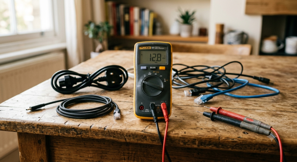
3.1 Entry-Level: Digital Multimeter (DMM)
- Best for: Home users, DIY hobbyists, beginner repair technicians
- Core features: Continuity beep mode + resistance mode covers 90% of everyday testing needs
- Pros: Affordable, widely available, simple to operate, useful for many other tasks
- Cons: Slow for multi-conductor cables; cannot automatically verify wiring order
3.2 Mid-Range: Dedicated Cable Tester
- Best for: Repair technicians, small-scale QA, network cabling installers
- Core features: Automatically scans multiple conductors in one pass; detects opens, shorts, and miswired pins
- Pros: Much faster than manual pin-by-pin testing; purpose-built for common cable types like Ethernet and USB
- Cons: Less versatile than a multimeter; designed mainly for cable testing
3.3 Professional: Automated Test Equipment (ATE)
- Best for: Factory production lines, professional laboratories, harness manufacturers
- Core features: All-in-one testing for continuity, shorts, insulation resistance, and dielectric withstand voltage; includes full pin mapping (verifying each pin connects to its correct matching pin on the opposite end) and generates standardized reports automatically
- Pros: High speed, high accuracy, with full data traceability for quality control and audit purposes
- Cons: High cost; unnecessary for everyday home use
3.4 Buying Advice for Most Users
- For checking home charging cables and Ethernet cords: a basic digital multimeter is more than enough.
- If you regularly repair cables or do cabling work: add a dedicated cable tester for your most common connectors.
- You do not need laboratory-grade precision for everyday use — the 2-wire method is perfectly sufficient for most consumer scenarios.
4. Step-by-Step Guide: Test Cable Continuity With a Multimeter
4.1 Preparation & Safety Rules
- Disconnect all power: Make sure the cable is completely unplugged from chargers, devices, and wall outlets. Never test a live cable — you can damage the meter or connected electronics.
- Visually inspect the cable: Check for cracked insulation, exposed metal, or broken plugs.
- Self-test the meter: Touch the two probes together. You should hear a beep and see a resistance reading near zero. This confirms the meter and leads are working.
4.2 Testing 2-Conductor Cables (Power Cords, Simple Charging Cables)
- Set the multimeter to continuity mode (beep symbol) or the 200 Ω resistance range.
- Touch one probe to the positive conductor on one end, and the other probe to the matching positive conductor on the opposite end.
- Read the result: a clear beep and stable low resistance mean the path is continuous.
- Repeat the same test for the negative/ground wire.
- Cross-check: Touch one probe to positive and the other to negative. You should not hear a beep. If you do, there is a short circuit.
4.3 Testing Multi-Conductor Cables (Ethernet, USB)
- Use the official pinout diagram as a reference, and test each pin pair one by one.
- Test two ways: confirm that wires that should connect do connect, and that wires that should not connect are fully isolated.
- For shielded cables: verify the shield is continuous end-to-end, and that the shield does not short to any internal conductors.
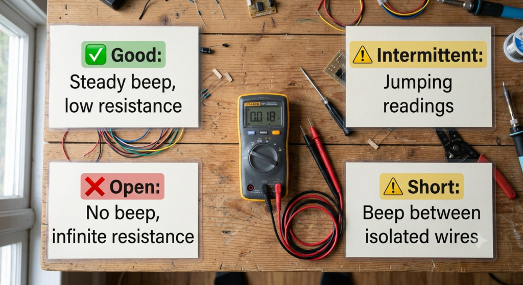
4.4 How to Read Your Results
| Observation | Status | Next Step |
|---|---|---|
| Steady beep, stable low resistance | Good continuity | Rule out basic connection issues; look for other causes of problems |
| Intermittent beep, jumping resistance | Poor / intermittent connection | Inspect plug roots and solder joints |
| No beep, infinite / OL reading | Open circuit (broken wire) | Narrow down the break point section by section |
| Beep between wires that should be isolated | Short circuit | Stop using the cable; locate insulation damage |
4.5 Common Interference & How to Fix It
- Dirty or oxidized contacts: Clean the metal terminals and press the probes firmly against clean copper before taking a reading.
- Temperature changes: Copper resistance rises slightly with temperature. Small fluctuations are normal.
- Long cable length: Long cables naturally have higher resistance. This is a normal property of the wire, not a fault.
5. Key Testing Tips for Common Cable Types
5.1 USB-C Charging & Data Cables
Key Conductors to Test
- Basic USB 2.0 cables: VBUS (power), GND (ground), D+, D- (data)
- Full-featured USB-C cables: Add high-speed differential pairs, CC configuration channels, and SBU auxiliary lines
Important Notes on CC Pins
The CC (Configuration Channel) pins handle cable detection, orientation detection, and USB Power Delivery communication.
⚠️ Common misconception: CC pins are not direct short-to-zero-ohm connections like power pins. On a standard cable, one side presents a pull-down resistor (typically 5.1 kΩ for a sink device). A simple continuity beep test will not show a dead short — and that is normal.
A basic continuity tester cannot fully verify USB-C CC functionality, since CC communication relies on resistor networks and digital protocol signaling, not just a simple low-resistance path. A missing or wrong resistance on CC lines is what causes fast-charging failures.
VBUS Power Path
The VBUS pins carry the main charging current. Higher-than-normal resistance here limits current capacity, causes extra heat, and increases voltage drop.
Bottom line: Good continuity alone does not guarantee fast charging. Wire gauge, total resistance, E-Marker chips, and PD protocol compatibility all play a role.
5.2 Ethernet (RJ45) Cables
- Core check: Verify all 8 conductors match the T568A or T568B wiring standard end-to-end.
- Shielded cables: Confirm the shield is continuous and not shorted to any internal wires.
- Limitation: Passing a continuity test does not guarantee gigabit speed. Problems like impedance mismatches and crosstalk are invisible to a basic continuity test.
5.3 HDMI / DisplayPort Video Cables
- These have many high-speed pins; always test against the official pinout diagram.
- Shield integrity directly affects picture quality, so always verify shield continuity.
- Common scenario: the cable passes continuity but the picture flickers or won’t run at maximum resolution. This is almost always a signal quality issue, not a continuity issue.
6. Continuity Testing in Cable Manufacturing
6.1 Why Factories Test Every Cable
During production and assembly, many connection-related defects can slip through. Continuity testing is the most cost-effective way to catch them before shipping.
Common defects caught by continuity testing:
- Misaligned or poorly crimped terminals
- Cold solder joints or missed solder points
- Wires pinned in the wrong order
- Internal breaks caused by handling or final testing
6.2 Typical Production Test Stages
Incoming Quality Control (IQC)
Sampling continuity tests on raw wire and terminals to verify conductor quality and consistency before production begins.
In-Process Quality Control (IPQC)
Continuity checks after critical steps like crimping, soldering, and assembly. This catches mistakes early, before defective units move further down the line.
Outgoing Quality Control (OQC)
100% full continuity testing on finished products before shipment. Results are recorded as proof of quality and for traceability.
Widely followed industry standards such as IPC/WHMA-A-620 define acceptance criteria for cable and wire harness assemblies. For higher-reliability applications, especially Class 2 and Class 3 products, manufacturers typically apply stricter inspection rules and maintain stronger test traceability records.
7. Common Faults & Troubleshooting
7.1 Open Circuit (Broken Wire)
- Symptoms: No beep; meter shows infinite / OL resistance
- Common causes: Copper strands broken from repeated bending, solder joint detached inside the plug, loose terminal
- How to locate: Use the half-split method. Test from the middle of the cable, then keep narrowing the range. Plug strain relief areas are the most common failure points.
7.2 Intermittent Continuity
- Symptoms: Connection comes and goes when you wiggle the cable; resistance jumps around
- Common causes: Partially broken copper strands, cold solder joint, loose contact spring inside the connector
- How to locate: Slowly bend and flex the cable while watching the meter. Where the reading suddenly changes is where the fault lives.
7.3 High-Resistance Continuity
- Symptoms: The meter beeps (or beeps weakly), but the resistance reading is clearly higher than normal
- Why it matters: This fault won’t kill the cable immediately, but it reduces charging speed, increases heat, and will often worsen over time until it becomes a full open circuit.
- Common causes: Oxidized conductors, under-crimped terminals, partially broken wire strands
7.4 Miswired / Reversed Pins
- Symptoms: Every wire tests good individually, but the cable doesn’t work when plugged in
- Common causes: Wrong pin assignment during assembly, wires soldered in reverse order during repair
- How to diagnose: Compare each pin against the official pinout chart one by one.
7.5 Short Circuit
- Symptoms: Low resistance / beep between wires that should be isolated
- Common causes: Damaged insulation exposing copper, solder bridges, pinched wires during assembly
- Safety warning: Never use a shorted cable. It can damage equipment, cause overheating, or create a fire risk.
- How to locate: Isolate conductors one at a time to find which pair is shorted.
8. Test Results, Documentation & Traceability
8.1 Record-Keeping for Home Users
For personal use, you only need to track the basics:
- Date of test, cable type / purpose
- Final result (good / open / short / poor connection)
- Suspected fault location
This helps you track cable condition over time and spot patterns of failure.
8.2 Industrial Test Reports
In manufacturing and professional QA, a standard test report usually includes:
- Product model and unique serial number
- Test date, operator name, equipment ID
- Full pin mapping results
- Measured resistance value for each circuit
- Final Pass / Fail judgment
For high-reliability products, complete records are maintained for audit and traceability purposes.
9. What a Continuity Test Can (and Can’t) Tell You
9.1 What It Does Well
- Quickly spot broken wires
- Verify correct wiring order on multi-conductor cables
- Detect basic faults like shorts and loose connections
- Work as a fast screening test for incoming goods or first-step troubleshooting
9.2 What It Cannot Verify
- Insulation quality and high-voltage withstand capability → requires insulation resistance / hi-pot testing
- Real current-carrying capacity and voltage drop → requires DC resistance / voltage drop testing
- High-speed data stability and signal quality → requires signal integrity testing
- Electromagnetic interference (EMI) immunity
- Mechanical lifespan and bend durability → requires flex / aging testing
9.3 Recommended Test Combinations
- Everyday home troubleshooting: Continuity test alone is usually enough
- Charging performance concerns: Continuity + DC resistance + voltage drop test
- High-speed data concerns: Continuity + signal integrity testing
- Safety-critical power use: Continuity + insulation resistance + dielectric withstand test
10. Frequently Asked Questions
Q1: Is a multimeter worth buying just for testing cables at home?
A basic digital multimeter is very affordable and useful for far more than just cables — checking batteries, testing switches, diagnosing small electronics, and more. For most households, it is a very practical tool to keep in a drawer.
Q2: What resistance value means a cable passes continuity?
Short cables will have very low resistance, but the exact number depends on wire gauge, length, and connector design. There is no universal pass/fail number. Always compare against the manufacturer’s published specification.
Q3: Can a continuity test find damaged insulation?
Only if the damage is bad enough that two conductors touch and create a short. A cable can have cracked or nicked insulation with no short circuit — and a continuity test will never see it.
Q4: Why do I get slightly different readings every time I test the same cable?
Small changes from probe pressure, contact position, and room temperature are normal. If readings jump wildly, you almost certainly have a loose or intermittent connection.
Q5: Is there any shock risk when doing a continuity test?
As long as the cable is fully disconnected from all power sources and devices, there is normally no shock risk. The test voltage output by the multimeter itself is extremely low and harmless under proper use.
Q6: My charging cable passes continuity but charges very slowly — why?
This is extremely common. Possible causes include undersized wire (high total resistance), a fault on the CC line, a broken E-Marker chip, or fast-charging protocol incompatibility. None of these show up on a basic continuity test.
Q7: How do I find an intermittent break that comes and goes?
Slowly flex and bend the cable section by section while watching the meter. The spot where the reading suddenly cuts in and out is your fault location. The area right where the cable exits the plug housing is the most frequent culprit.
11. Quick Reference Toolkit
11.1 Continuity Test Cheat Sheet
- Safety rule first: Disconnect power, self-test the meter, then test the cable.
- Fault mnemonic:
- No response at all → look for an open break
- Comes and goes → look for a loose / cold connection
- Runs hot under load → look for high resistance
- Breaks devices → look for a short circuit
11.2 Common Pinout References
Use official diagrams for:
- USB-A, USB Type-C, RJ45 Ethernet, HDMI, and XLR connectors
11.3 Home Buyer’s Tip
- Entry-level pick: A basic digital multimeter with continuity beep and resistance ranges
- Avoid overbuying: Premium models with extra features are overkill for casual home cable testing
Final Thoughts
A continuity test is the quickest, simplest first check you can run on any cable — think of it as taking a cable’s pulse. It will catch the most common failures in seconds.
But remember: a pulse doesn’t tell you everything about a person’s health, and continuity doesn’t tell you everything about a cable’s performance. For charging speed, data speed, and electrical safety, you need to look deeper.
Used correctly, it is still the single most valuable first test in any cable troubleshooting toolkit.