
Quick Summary
Cable voltage drop is the natural reduction in voltage as electricity travels through a conductor, caused by the cable’s inherent electrical resistance and governed by Ohm’s Law (V = I × R). This lost energy converts directly into heat, which wastes power, slows charging speeds, and can create safety risks over time.
For everyday users, basic voltage drop testing requires only a digital multimeter and a working load — no lab gear needed. For professional or high-precision results, engineers use programmable electronic loads and 4-wire Kelvin testing to measure milliohm-level resistance.
Industry guidelines from NEC and IEC recommend keeping total voltage drop under 5% for general power circuits and under 3% for lighting or sensitive electronics. For USB-C fast charging cables, excessive voltage drop may cause power throttling, lower charging power, or unstable operation depending on the charger and device design.
1. What Is Cable Voltage Drop?
1.1 A Simple Analogy
Think of electrical cables like water pipes. If a pipe is narrow, long, or partially clogged, water pressure at the faucet will be lower than at the source. Electricity works the same way: the cable itself is the “pipe,” and electrical resistance is the “friction” that saps voltage along the path.
What comes out the end is always slightly less than what went in — this difference is voltage drop.
1.2 The Physics Behind It
All conductive materials resist electron flow to some degree. As current pushes through the conductor, some electrical energy is converted into thermal energy (heat) and dissipates into the air. This is not a design flaw; it is a fundamental physical property of all real-world conductors.
1.3 Key Terms Clarified
- Voltage Drop: The voltage difference between the input and output ends of a single cable or wire run, caused purely by conductor resistance.
- Voltage Loss: The total voltage drop across an entire system, including switches, connectors, fuses, and transformers — not just the cable itself.
- Power Loss: The amount of electrical energy wasted as heat, calculated from current and voltage drop.
2. Why Voltage Drop Matters More Than Ever
2.1 The Low-Power Era Was Forgiving
In the days of 5V/1A USB chargers, voltage drop was barely noticeable. At such low currents, even a cheap cable lost only a tiny fraction of a volt, and charging speed barely suffered. Most users never knew it existed.
2.2 Fast Charging Changed Everything
Modern USB PD systems deliver 60W, 100W, 140W, and even 240W through the same small USB-C connector. To hit these power levels, current has jumped dramatically — up to 5A in standard cables.
Because power loss scales with the square of the current (P = I²R), doubling the current quadruples the heat and wasted energy. A cable that worked fine at 2A can become a bottleneck — and a heat hazard — at 5A.
2.3 Real-World Consequences
- Charging slowdowns: If voltage at the device end drops too far, the charger and phone/laptop may renegotiate to a lower power level.
- Premature aging: Constant high heat breaks down insulation and weakens solder joints over time.
- Safety risks: In high-current DC systems like car inverters or solar setups, excessive drop can lead to melted connectors and even fire.
3. Core Principles & Calculation Formulas
3.1 Ohm’s Law: The Foundation
Every voltage drop calculation traces back to one simple formula:
V = I × R
- V = Voltage drop (volts)
- I = Current flowing through the cable (amps)
- R = Total loop resistance of the cable (ohms)
3.2 Always Calculate the Full Loop
This is the single most common beginner mistake. Current flows out on the positive wire and back on the negative wire — both contribute to resistance.
Total Vdrop = I × (Rpositive + Rnegative)
If you only measure or calculate one wire, your number will be half of the real value.
3.3 Power Loss Formula
To find how much energy is turning into heat:
P = I² × R
This explains why 5A charging generates so much more heat than 3A — the loss grows with the square of the current.
3.4 Quick Example Calculation
Take a single 24 AWG copper wire, 1 meter long, carrying 5A:
- 24 AWG copper resistance ≈ 0.0894 Ω/m at 20°C
- Loop resistance (2 wires) ≈ 0.179 Ω
- Voltage drop = 5A × 0.179 Ω ≈ 0.9V
- Power loss = 5² × 0.179 ≈ 4.5W
Note: Real USB-C power cables often use multiple parallel conductors or thicker dedicated power wires, so actual resistance can be much lower than a simple single 24 AWG wire calculation. Quality 100W cables typically measure well under 100 mΩ total loop resistance.
3.5 AC vs. DC Systems
- DC (USB cables, car wiring, solar): Only resistance matters for short runs. Calculations are straightforward. For normal USB-C users, DC resistance is the main factor to consider.
- AC (house wiring, long extension cords): For short, low-frequency runs, AC and DC drop are nearly identical. For very long runs or high frequencies, inductive reactance adds slightly to total impedance, but this is rarely a concern for everyday household use.
3.6 Temperature Makes It Worse
Copper’s resistance rises as it gets hotter — about 0.393% per degree Celsius. A cable that warms up under load becomes more resistive, which makes it drop more voltage, which makes it hotter still. This vicious cycle is why overloaded cables fail unexpectedly.
4. Tools & Safety Prep for Testing
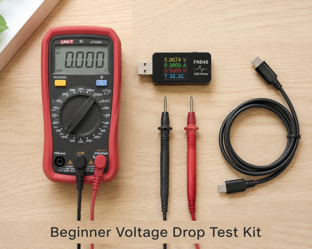
4.1 Beginner Toolkit (Most Users)
- Digital multimeter (DMM): For measuring voltage and basic resistance.
- Is True RMS necessary? For DC USB cable testing, a standard high-accuracy multimeter works perfectly well. True RMS becomes important when measuring AC voltage on irregular, non-sinewave loads like motor drives or dimmers. For most charging and DC tests, it is not a requirement.
- USB power meter: The easiest way to check input/output voltage on charging cables.
- Clamp meter (optional): For measuring live current without breaking the circuit.
- A real load: Your phone, laptop, or a known-power device works fine.
4.2 Professional Toolkit
- Programmable electronic load + USB PD trigger: For precise, repeatable current testing.
- 4-wire (Kelvin) milliohm meter: Eliminates test lead resistance for milliohm-accurate readings.
- Thermal imaging camera / infrared thermometer: For mapping hot spots and connector issues.
4.3 Non-Negotiable Safety Rules
- Never use the resistance setting on a live circuit. It will damage your meter and can be dangerous.
- For household AC: Work carefully, use properly rated test leads, and never work alone on energized circuits.
- For high-current DC: Watch for short circuits and hot connectors. Disconnect the negative terminal first when working on batteries.
5. Step-by-Step Testing Methods
5.1 Method 1: Loaded Direct Measurement (Most Useful)
This is the most realistic test because it measures drop under actual operating conditions.
- Connect and power up your load so current is flowing.
- Set your multimeter to DC/AC voltage mode matching your system.
- Measure voltage right at the source end of the cable. Write it down.
- Measure voltage right at the device/load end. Write it down.
- Subtract:
Input Voltage − Output Voltage = Voltage Drop - For percentage:
(Drop / Input Voltage) × 100 = % Drop
Best for: Real-world verification, troubleshooting, everyday user testing.
5.2 Method 2: Multimeter Continuity/Resistance Test
With the cable completely disconnected and unpowered:
- Set your meter to the lowest resistance range.
- Short the positive and negative pins together at one end.
- Measure resistance from the other end — this is your full loop resistance.
- Calculate expected drop with V = I × R for your target current.
Note: Cheap multimeters struggle below ~0.1Ω, so this works best for comparing cables rather than absolute precision.
5.3 Method 3: 4-Wire Kelvin Test (Highest Precision)
Professional labs use this to eliminate test lead and contact resistance error. Two wires supply a known constant current, and two separate wires sense the voltage across the sample.
This method can measure down to milliohms reliably and is the gold standard for cable quality control and R&D.
5.4 Method 4: Segmented Drop Testing (Troubleshooting)
When total drop is too high, hunt down the bad spot by measuring across each section:
- Source → fuse/breaker
- Fuse → switch
- Switch → connector
- Connector → load
The segment with the biggest drop is your problem point. Almost always, it is a loose, oxidized, or undersized connector — not the wire itself.
6. Use Case Testing Guides
6.1 USB-C Fast Charging Cables (Deep Dive)
Test Setup
PD Charger → Test Cable → Electronic Load / Device
Example: Testing a 100W USB-C Cable Step by Step
- Plug a certified 100W (or higher) PD charger into wall power.
- Connect the cable under test to the charger.
- Attach a USB PD electronic load (or a laptop running at full power) to the other end.
- Set the load to draw 20V / 5A (the full 100W rating).
- Use a multimeter or USB power meter to record voltage at the charger-side connector.
- Record voltage at the device-side connector.
- Subtract to get total voltage drop, and note the temperature of both connectors after 10–15 minutes of steady load.
Per USB-IF functional specifications, the maximum allowable VBUS IR drop through a cable at its rated current is 500 mV, with ground drop limited to 250 mVUSB-IF.
What to Expect by Power Rating
- 60W (20V/3A): Most decent cables handle this easily. Drop is rarely a problem.
- 100W (20V/5A): Requires thicker power conductors and an E-Marker chip to tell the charger it can carry 5A. Poor-quality cables will drop enough voltage to drop back to 3A/60W.
- 240W PD 3.1 EPR (48V/5A): The most demanding spec, with strict limits on both resistance and temperature rise. Only fully certified EPR cables should be used at this level.
How Drop Affects Fast Charging
USB PD works by negotiating voltage levels (PDOs) between charger and device. If the cable drops too much voltage, the device sees a voltage below the PDO threshold and may request a lower power level, adjust PPS settings, or operate at reduced efficiency.
Good Cable vs. Bad Cable: Side-by-Side (1m, 5A test)
| Parameter | Quality 100W Cable | Cheap “100W” Cable |
|---|---|---|
| Loop resistance | ~60 mΩ | ~180 mΩ |
| Voltage drop | ~0.3V | ~0.9V |
| Power loss | ~1.5W | ~4.5W |
| Surface temperature | Slightly warm | Noticeably hot at plugs |
| Charging behavior | Holds full 100W steady | Throttles, drops to lower power |
6.2 Automotive & RV 12V/24V Systems
- Test starter cables during cranking — hundreds of amps flow, and even a little resistance causes huge voltage drop.
- Always test the ground/negative path separately; bad chassis grounds are the #1 hidden cause of electrical gremlins.
- For inverter installs, aim for less than 0.5V drop at full load.
6.3 Solar PV DC Strings
- Long string runs eat directly into your harvest. Every volt lost is power you never see at the inverter.
- MC4 connectors add measurable contact resistance that gets worse with age and UV exposure. Test them periodically.
6.4 Household Extension Cords
- Long extension cords for power tools, space heaters, or EV charging need extra-thick conductors.
- If your drill feels weak or your charger runs hot, voltage drop is almost always the reason.
7. Key Factors That Determine Voltage Drop
7.1 Cable Itself
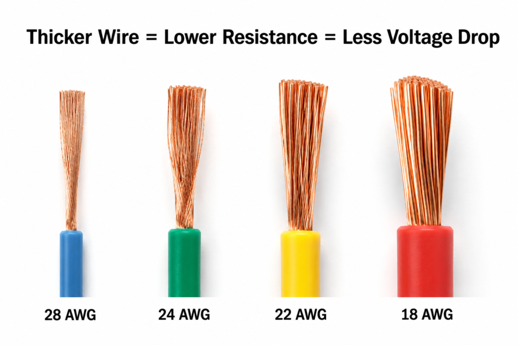
- Conductor material: Pure copper is best. Aluminum and copper-clad aluminum (CCA) have ~68% higher resistance for the same size.
- Wire gauge / cross-section: Thicker wire = lower resistance. In AWG, a smaller number means a thicker wire.
- Length: Resistance grows linearly with length. Double the length, double the drop — and don’t forget the return path.
7.2 Operating Conditions
- Current level: Drop is directly proportional to current. More amps = more drop.
- Temperature: Hot cables have higher resistance. Bundled cables in walls or conduits run hotter and drop more voltage.
- Power factor (AC only): Inductive loads like motors make AC drop slightly worse than pure resistance would predict.
7.3 Installation Quality
- Connector craftsmanship: A bad crimp, dirty pin, or loose screw can add more resistance than meters of cable.
- Wire routing: Tight bends, crushed insulation, and parallel runs can degrade performance.
- Parallel cables: If you parallel two cables to carry more current, uneven current sharing can cause one to run hotter than expected.
8. Industry Standards & Acceptable Limits
8.1 Widely Cited Reference Standards
- NEC / NFPA 70 (US): An informational note (not a mandatory code rule) recommends maximum 3% drop on branch circuits and 5% total for feeder + branch combined. This is the most widely followed guideline in North America.
- IEC 60364 series (International): Provides guidance for voltage drop design in low-voltage electrical installations, with commonly used design targets around 4% depending on application and national implementation rules.
- UL 83 / UL 758: Define conductor resistance limits for different wire types and temperature ratings, which indirectly set voltage drop performance.
8.2 Quick Reference Table
| Application | Nominal Voltage | Recommended Max Drop | Notes |
|---|---|---|---|
| AC lighting circuits | 120V / 230V | 3% | NEC recommended practice |
| AC general power circuits | 120V / 230V | 5% | Acceptable for motor loads |
| 12V automotive / DC systems | 12V | 3% (0.36V) | Starter circuits may see higher transient drop |
| 24V solar / RV systems | 24V | 3% (0.72V) | Critical for inverter input |
| USB-C fast charging cables | 5V – 48V | ~0.5V industry reference | Per USB-IF specs, VBUS drop ≤ 500mV at rated current; actual performance depends on charger and device |
| Precision / medical equipment | Device-specific | 1% – 2% | Much tighter requirements |
9. How to Interpret Results & Fix Excessive Drop
9.1 Reading Your Test Results
Example test report for a 100W USB-C cable:
- Input voltage: 20.0V
- Output voltage: 19.5V
- Current: 5A
- Voltage drop: 0.5V (2.5%)
- Peak connector temp: 40°C
Verdict: Within typical acceptable range. No throttling expected, temperatures are normal, cable is performing as it should.
9.2 When You Have a Problem
If drop is too high, solutions are listed from most effective to least:
- Use a thicker cable (larger cross-section / lower AWG number). This is the single biggest fix.
- Shorten the run. Move the power source closer to the load.
- Upgrade connections. Clean contacts, replace cheap connectors with gold-plated or tinned ones, use proper crimps.
- Split the load. Run two smaller circuits instead of one overloaded one.
- Raise system voltage. For the same power, a 24V system draws half the current of a 12V system — cutting drop roughly in half.
10. Common Mistakes & Troubleshooting
10.1 Mistakes Everyone Makes
- Testing with no load: If no current is flowing, drop is zero. Your reading tells you nothing.
- Only testing one wire: Forgetting the return path gives you half the real picture.
- Testing cold: A cable that looks fine on the bench can exceed limits after 15 minutes under load.
- Confusing AC and DC: AC drop includes reactance; DC does not. They are not identical on long runs.
10.2 Troubleshooting Flowchart
- Verify your meter, settings, and probe connections — rule out measurement error first.
- Inspect all connectors, plugs, and terminals for dirt, corrosion, or looseness.
- Test each segment of the run to isolate the high-resistance point.
- Verify the wire gauge and material — counterfeit and CCA cables are extremely common.
- Confirm the load current matches what you expected.
11. Frequently Asked Questions
Q: Is 5% voltage drop okay?
A: It is generally considered acceptable for general-purpose power circuits. For lighting, sensitive electronics, or 12V DC systems, 5% is quite high and likely to cause problems.
Q: Which is more accurate — measuring drop directly or measuring resistance?
A: A 4-wire resistance test is more precise for the conductor itself, but a loaded voltage test better reflects real-world performance, including dynamic contact issues. They complement each other.
Q: Why does my USB-C cable get hot while charging?
A: Heat comes from power lost to cable resistance (P = I²R). A little warmth is normal at 100W, but if the connector feels hot to the touch, it usually means the cable has high resistance, undersized conductors, or poor connector quality. Excessive heat speeds up wear and can be a safety risk.
Q: Does a longer USB-C cable charge slower?
A: All else being equal, yes. Longer cables have higher total resistance, which creates more voltage drop at the same current. If the drop is large enough, the device and charger will negotiate a lower power level. High-quality long cables use thicker conductors to keep resistance low, so a well-made 2m cable may outperform a cheap 1m cable.
Q: How can I test if my USB-C cable supports 100W?
A: First, check for an E-Marker chip (most USB power meters will detect it). Then run a loaded voltage drop test at 20V/5A. If the cable can hold 5A continuously without excessive voltage drop (>0.5V) or overheating, it is functionally capable of 100W. Cables without E-Marker will usually be limited to 3A (60W) by the charger.
Q: Does a more expensive USB-C cable always have lower drop?
A: Not always. Price includes branding, shielding, durability, and certification fees. Drop depends mainly on conductor gauge, material, and build quality — always test, don’t assume.
12. Final Thoughts & Action Steps
Cable voltage drop is the hidden thief of your charging speed, solar harvest, and electrical efficiency. The good news is that you don’t need an engineering degree to test for it — a basic multimeter and a working load are enough to spot the worst offenders.
Starter Kit Recommendation
- 1 standard digital multimeter (True RMS not required for basic DC testing)
- 1 set of sharp-tipped test probes
- 1 USB power meter (if you test a lot of charging cables)
Try It Today
Grab the USB-C cable you use most for laptop charging, or the extension cord you run out to your garage workshop. Measure voltage at both ends under load, and see how much power is being turned into heat before it ever reaches your device. You might be surprised what you find.