
1. Why Understand Dock Architecture?
1.1 The Interface Dilemma of Thin & Light Laptops
Modern laptops are getting slimmer every year, and the number of ports on the device body keeps shrinking. Many models now only retain USB-C ports. The core value of USB-C lies in its ability to handle charging, file transfer, and video output all through a single connector, delivering true multi-functionality in one port.
But with fewer ports, connecting a USB drive, mouse, monitor, and Ethernet cable at the same time becomes a challenge — which is why USB-C docks have become an essential accessory for many users. Many people think a dock is just a simple adapter that splits one port into several. In reality, it is far more complex: it is essentially a miniature interface scheduling system with a complete internal hardware architecture that coordinates different functions running simultaneously.
1.2 A Dock Is Not a USB Hub
Many people confuse USB-C docks with regular USB hubs, but the two have fundamentally different architectures:
- USB Hub: Only splits one USB data channel into multiple, with a single data expansion path — like a main road branching into a few side roads.
- USB-C Dock: A multi-system collaborative device that combines power delivery, video, data, and networking. It acts as a small interface hub that manages power distribution, handles video signal conversion, and coordinates multi-channel data transmission, with far higher complexity.
This is why cheap hubs cost only a few dollars, while premium docks cost hundreds or even thousands of dollars. The price gap stems from architectural differences in chip count, protocol complexity, and power delivery design.
2. The Technical Foundation of Dock Operation
2.1 USB-C Connector: The Physical Basis of Multi-Functionality
A standard USB-C connector has 24 metal pins inside, each with a clear role: some handle high-current power delivery, some handle high-speed data transmission, some handle device detection, and others are dedicated to video signals.
The reason one port can charge, transfer files, and connect a monitor at the same time is the pin division and time-division multiplexing mechanism — different functions use different pins without interfering with each other.
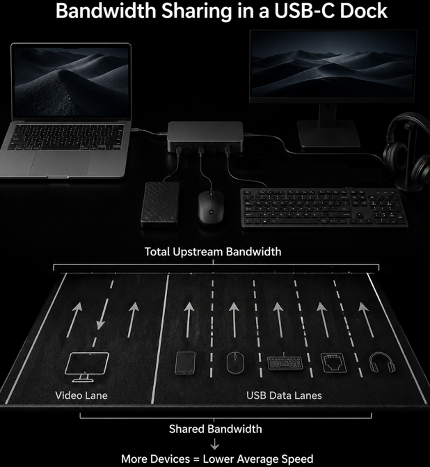
Among these, high-speed data lanes are the most scarce resource. Think of them as highway lanes: the total number of lanes is fixed. If more lanes are allocated to video, fewer lanes remain for data transfer, and this directly defines the performance limit of the dock.
2.2 Four Core Protocols: The Operating Rules of Docks
If pins are the hardware foundation, protocols are the “rulebook” that governs dock operation. Four core protocols enable all functions:
- USB Power Delivery (PD) Protocol: The power negotiation mechanism. When a dock connects to a charger and a laptop, it “communicates” with both ends to confirm supported charging power, and finally settles on a suitable voltage and current. This is the core premise for a dock to deliver reverse charging to the host laptop.
- DisplayPort Alt Mode: The native video output protocol. It allows the high-speed pins of the USB-C port to transmit video signals directly without extra conversion, and it is the mainstream video output solution today.
- USB 3.x / USB4 Protocol: The bandwidth standard for data channels, defining the upper speed limit of data transmission. Like the speed limit on a highway, it directly determines how fast files can be transferred.
- Thunderbolt Protocol: The core of high-end docks. It combines PCIe, USB, and video signals into a single transmission channel, offering higher bandwidth and stronger functional scalability.
3. Internal Hardware Architecture of a USB-C Dock
3.1 Overall Architecture Overview
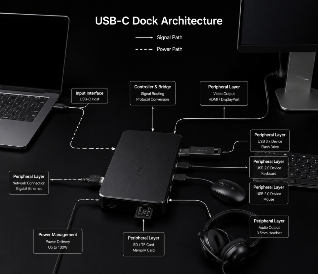
A complete USB-C dock is internally divided into four core layers, with two independent paths running through it:
Four Core Layers: Input Interface Layer, Main Controller & Bridge Layer, Peripheral Function Layer, Power Management Layer
Two Independent Paths:
- Signal Path: Transmits all digital signals including data, video, and network traffic
- Power Path: Handles power input, distribution, and output to power all internal modules and connected peripherals
3.2 Input Interface Layer: The Entry Point for Signals and Power
This is the first gateway where the dock connects to the host computer, centered around the USB-C receptacle and supporting detection circuits.
The Configuration Channel (CC) pins are the “scouts” of this layer, with three core roles:
- Identify the type of plugged-in device (laptop, charger, or other device)
- Detect plug orientation and automatically adjust signal transmission direction
- Trigger PD charging negotiation and start subsequent function initialization
Additionally, this layer includes ESD protection and impedance matching circuits to protect internal chips from electrostatic damage and signal interference.
3.3 Main Controller & Bridge Layer: The “Brain” of the Dock
This is the most core part of the dock, responsible for lane allocation, protocol conversion, and multi-module coordination — equivalent to the traffic control center of the entire hub.
There are two mainstream architectural solutions today:
- Discrete Multi-Chip Architecture: Common in entry-level docks. It uses three separate chips working together: a USB hub controller, a video conversion chip, and a PD controller. It has lower cost but average coordination efficiency.
- Single-Chip Integrated Architecture: Common in mid-to-high-end docks. A single USB4 or Thunderbolt main controller handles all protocol processing and lane scheduling. It offers higher efficiency and stronger performance, but also higher cost.
3.4 Data Expansion Module: The USB Hub Subsystem
This module is the source of the multiple USB ports on a dock. Its core is the USB Hub Controller, which expands one upstream USB data channel into multiple downstream ports for USB drives, mice, external hard drives, and other devices.
It is important to note that all downstream USB ports share the total upstream bandwidth. Just like a 4-lane main road branching into 8 side roads, all side road traffic must merge into the main road. The more devices connected at the same time, the slower the average speed each device gets.
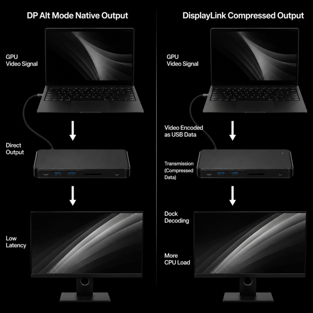
3.5 Video Output Module: Two Technical Paths
There are two completely different architectural schemes for video output on docks, with significant experience differences:
| Comparison Dimension | DP Alt Mode Native Output | DisplayLink Compressed Output |
|---|---|---|
| Signal Path | PC GPU → USB-C high-speed pins → direct output from dock | PC compresses video into data → transmits via USB channel → decoded by dock for output |
| Latency | Extremely low, almost no delay | Noticeable latency, more obvious with dynamic footage |
| Bandwidth Usage | Uses dedicated high-speed video lanes, does not consume USB data bandwidth | Occupies USB data channel, competes for bandwidth with other USB devices |
| Host Load | Almost no extra load on the computer | Consumes some CPU/GPU resources for encoding |
| Compatibility | Depends on host support for DP Alt Mode | Works with any USB port, wider compatibility |
In simple terms, native output delivers great image quality and low latency, but has requirements for the host computer. Compressed output has wider compatibility, but occupies USB bandwidth and adds extra load to the computer.
If converting to other video interfaces like HDMI or VGA, an additional protocol conversion chip is required to complete signal format conversion.
3.6 Power Management Module: The Power Steward
The power management module ensures stable operation of the dock, with a PD controller at its core. It is responsible for four key tasks:
- Identify the power of the connected charger and negotiate charging specifications
- Distribute power: how much goes to reverse charging the laptop, how much powers the dock itself, and how much goes to connected peripherals
- Control power output to each port
- Over-current and over-voltage protection to prevent device damage
The power flow works as follows: when a charger is connected to the dock, part of the power goes back to charge the laptop through the USB-C port, part powers the dock’s internal chips, and the rest is distributed to downstream ports to power peripherals like USB drives and external hard drives.
High-power docks also require dedicated DC-DC conversion circuits and thermal design to ensure stable operation under high current.
3.7 Peripheral Function Layer: Collection of Additional Features
Ethernet ports, headphone jacks, and memory card slots on a dock all belong to the peripheral function layer.
These functions are essentially independent USB peripherals: the Ethernet port uses a USB-to-Ethernet controller, the audio port uses a USB audio codec chip, and the card reader uses a USB card reader controller. They all connect under the USB hub controller, like individual devices plugged into a USB splitter.
4. The Full Workflow of a Dock From an Architecture Perspective
4.1 Full Initialization Process
When we plug a dock into a laptop, it seems to work instantly. In reality, a complete set of initialization steps has already taken place inside:
- Physical Connection Detection: CC pins detect device insertion, identify device type and plug orientation
- Charging Power Negotiation: PD protocol starts, communicating with the laptop and charger to confirm charging power and direction
- USB Device Enumeration: The laptop recognizes the dock’s USB hub and various peripheral controllers
- High-Speed Lane Allocation: Switches to the corresponding Alt Mode, allocating high-speed lanes to video or data transmission
- Module Initialization Complete: All functional modules start up and enter normal working state
4.2 Experience Differences Between the Two Video Paths
The native video path is like a direct high-speed train: video signals travel from the computer’s GPU directly to the monitor through a dedicated channel, with no extra processing in between. That is why it is fast and delivers great image quality.
The compressed video path is like a package delivery service: the video is first split into data packets, transported over the regular USB “road”, then reassembled into a video signal at the dock. This introduces latency and also takes up capacity on the shared road.
4.3 Bandwidth Allocation Logic for Concurrent Multi-Device Use
The total upstream bandwidth of a dock is fixed, just like the total number of lanes on a highway.
Many entry-level docks only have 4 high-speed lanes. When video output is enabled, it takes up 2 lanes, leaving only 2 lanes for USB 3.x data transfer. The speed is naturally cut in half — this is the root cause of the common complaint: “when I connect a monitor, my USB file transfer slows down”.
USB4 and Thunderbolt docks have much higher total bandwidth and more high-speed lanes, like a wider highway. Even after allocating lanes for video, there are still enough lanes left for high-speed data transfer, so bandwidth conflicts are rare.
5. Architectural Differences Between Three Main Types of Docks
Docks on the market today fall into three main categories, with different architectures, positioning, and user experiences:
| Product Category | Architectural Features | Performance Limit | Ideal Use Case |
|---|---|---|---|
| Entry-Level USB-C Dock | Discrete multi-chip solution: USB 3.x hub + DP video + independent PD chip | Video mostly limited to 4K 30Hz, obvious USB bandwidth sharing | Daily office work, connecting mice, keyboards, USB drives and other light peripherals |
| Mid-Range USB4 Dock | Single USB4 main controller, unified scheduling of all high-speed lanes | 40Gbps total bandwidth, supports multi-monitor high refresh rate, high-speed external SSD | Content creation, multi-monitor office work, frequent large file transfers |
| Professional Thunderbolt Dock | Thunderbolt main controller, native PCIe lane support | In addition to USB/video, supports external high-speed SSDs, professional network cards, eGPUs | Professional workstations, video post-production, high-performance peripheral connections |
6. Explaining Common Performance Issues Through Architecture
6.1 Why Can Prices Vary by Multiple Times?
The price gap between an inexpensive dock and a premium dock comes down to four main factors:
- Chip Cost: There is a huge price difference between discrete chips and integrated main controllers. The cost gap between basic 100Mbps Ethernet and 2.5G/10G Ethernet is also very large.
- PCB Design: High-speed signals have strict requirements for PCB layer count and trace precision. High-end docks use more PCB layers, which significantly increases cost.
- Power & Thermal Design: High-power charging solutions require better conversion circuits and thermal design, driving up material costs.
- Certification Cost: Products with official USB-IF certification or Thunderbolt certification require certification fees, adding compliance costs.
6.2 Why Does USB Speed Drop When Connecting a Monitor?
This is a typical architectural limitation of entry-level docks: DP Alt Mode video output occupies 2 sets of high-speed differential lanes. With only 4 lanes originally available for USB 3.x, only 2 remain, cutting bandwidth directly in half. Naturally, transfer speeds slow down.
USB4 and Thunderbolt docks generally do not have this problem, thanks to their sufficient total bandwidth and more flexible lane scheduling.
When shopping, look for product specifications that state “USB 3.2 full speed with video output” — this indicates a more thoughtful lane design.
6.3 Why Do Docks Usually Run Warm?
When a dock is working, multiple chips run simultaneously: the power conversion chip, USB hub controller, video conversion chip, and network card chip all generate heat.
Especially when working with high bandwidth and multiple connected devices, signal conversion produces significant losses that turn into heat. Premium docks improve thermal performance through architectural optimizations like metal casings and internal heat sinks, while cheaper docks have simpler thermal design and run hotter.
7. Architectural Evolution: The Future of Docks
7.1 USB4 Version 2.0: 80Gbps Bandwidth Reshapes Lane Allocation
The new generation of USB4 protocol raises total bandwidth to 80Gbps, effectively doubling the width of the highway. Future docks will be able to drive more high-speed peripherals at the same time, support higher-spec video output, and lane allocation will become more flexible, further reducing bandwidth conflicts.
7.2 Thunderbolt 5: 120Gbps Bandwidth and PCIe 4.0 Upgrade
Thunderbolt 5 boosts bandwidth to 120Gbps and upgrades to PCIe 4.0 lane support. For professional users, future Thunderbolt docks will support more powerful PCIe devices and 8K multi-monitor output, taking creative workflow performance to the next level.
7.3 USB PD 3.1 EPR: Architectural Upgrade for 240W Power Delivery
The new generation of PD protocol supports up to 240W charging power, and dock power modules will be upgraded accordingly. In the future, gaming laptops and mobile workstations will also be able to charge at full power through a dock, expanding the use cases for high-performance docks.
8. Conclusion
When shopping for a dock, many people only count the number of ports and think “more ports = better value”. This is actually the biggest misconception.
The essence of a USB-C dock is not a simple one-to-many adapter, but a miniature interface system with multiple chips working in coordination. Its performance ceiling, thermal performance, and stability are all fundamentally determined by its internal architecture.
Once you understand the architectural logic of docks, it becomes clear: the key to choosing a dock is looking at the controller solution and lane design, not just counting ports.